Solidworks file format for 3d printing
How Do I 3D Print from SOLIDWORKS
TriMech Video Tech Tips, 3D CAD, SOLIDWORKS, Tech Tips
By David Cano-Mejia on
As 3D printing becomes more common in the workplace, users are turning to SOLIDWORKS to better understand their designs in the context of 3D printing. SOLIDWORKS offers several 3D printing visualization and analysis tools and all of them can be accessed through the Print3D tool (File > Print3D). Let’s take a look!
Does My Part Fit on My Printer?
The first step in analyzing your design for 3D printing is to ensure that it will fit inside the print area. Under Printer, you can select the 3D printer that you will be using. If this is your first time using the Print3D command, you will need to add your printers to your favorites list. Click on Manage Favorites to browse all available 3D printers. SOLIDWORKS has added a comprehensive list of 3D printers with up-to-date envelope information so you can quickly find your most used printers and add them to your Favorites for easy access. If for some reason your 3D printer is not listed under this library, you can define a Custom Printer by manually inputting the print volume dimensions.
Under Print Bed Location select a plane, or planar face, to be defined as the bottom plane of the model. This will automatically orient your model on the print bed. If the model is larger than the print volume, the geometry outside the print volume will be highlighted in red and you will not be able to print. If you need to change the orientation of the model, you can use the translation controls, manually type in the desired print bed angle and offsets in the Print3D PropertyManager, or click Orient to Fit to let SOLIDWORKS orient your part or assembly for you.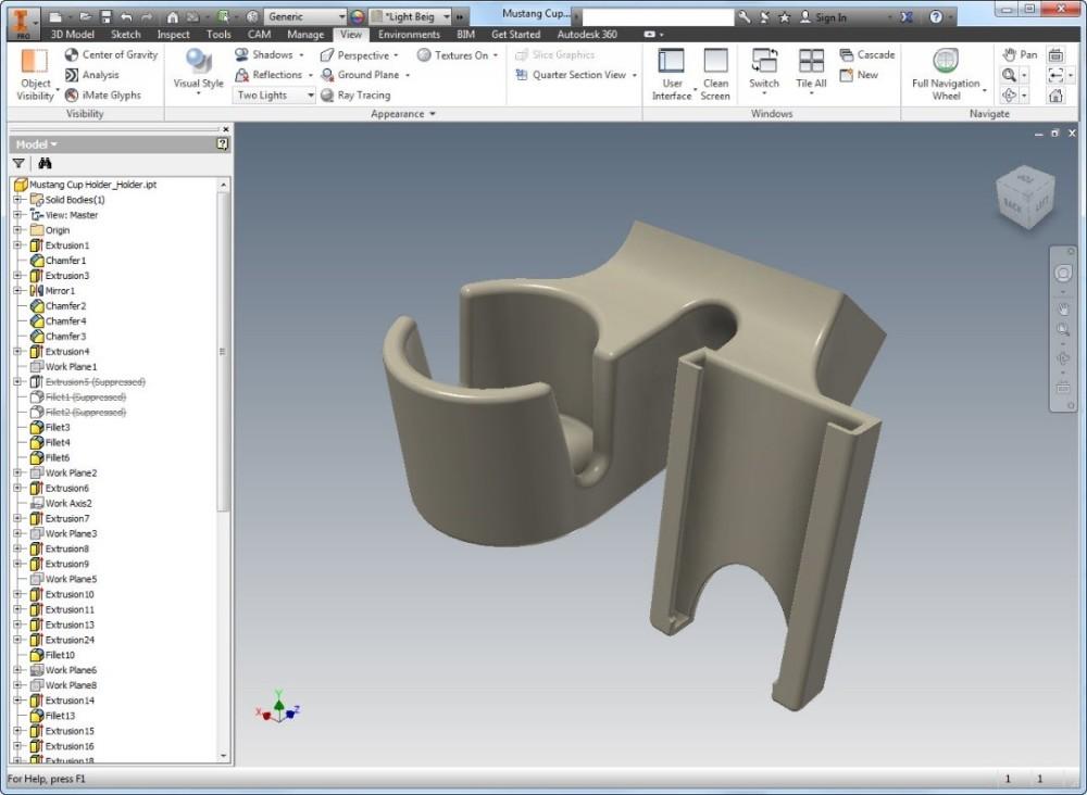
Under Scale, you can also choose to print your design at a scale other than 1, which is the current size of the model in SOLIDWORKS. To do so, type a value for the scale factor. The new value is saved as a document property in the SOLIDWORKS file so if you print the model again, the saved value is used still there. The Scale to Fit option sets the scale to the largest value that will still fit inside of the print volume.
Can I Analyze My 3d Print?
Sure! You just have to switch over to the Preview tab in the Print3D PropertyManager. There are several analysis tools that you can use to get a better understanding of the design to be printed.
- Build Analysis
- This allows you to preview the faces of your model that may require supports. Depending on the printer being used, at a certain overhang angle, the print quality is greatly affected unless supports are used. Type in the maximum angle for the faces that will require support.
 I recommend changing the Support face color to red and checking Show As Transparent to make it easy to visualize all of the faces that will need support.
- This allows you to preview the faces of your model that may require supports. Depending on the printer being used, at a certain overhang angle, the print quality is greatly affected unless supports are used. Type in the maximum angle for the faces that will require support.
- Layer Height
- This option lets you visualize the height of each print layer in order to determine whether the print resolution is sufficiently fine to produce the desired print. Type in a layer height and turn on Show Striation Lines in order to get a preview.
- If you are planning on exporting your file as a .3MF (3D Manufacturing Format), you can choose to let SOLIDWORKS generate the slices for the 3D print and embed those into the .3MF file instead of slicing the model using the printer’s slicer software
- Thickness/Gap Analysis
- If you are using FDM (Fused Deposition Modeling) for your prints, this calculates the ideal wall thickness/gap based on the material that you set and the layer height.
How Do I Export the File to Be 3D Printed?
When you are done analyzing and visualizing your design, you are ready to export the 3D print files.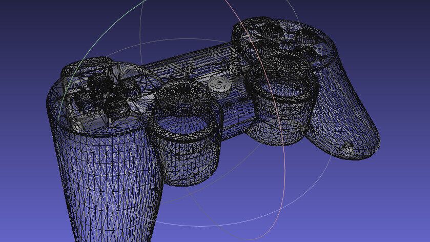 You can export part and assembly files to STL (.stl), 3D Manufacturing Format (.3mf), or Additive Manufacturing File Format (.amf) files.
- STL (*.stl)
- This ASCII or binary format file describes only the surface geometry of a 3D object as a raw, unstructured triangulated surface.
- 3D Manufacturing Format (*.3mf)
- This is a 3D focused file format that contains 3D model, material, and property information for sharing full-fidelity 3D models to other applications, platforms, services, and printers.
- Additive Manufacturing File (*.amf)
- This xml-based file lets you select export options that store the color, scale and materials of the object to be 3D printed in the .AMF file, as well as the geometry of the model.
Under Save To File, select your desired format and click Save File. Once you have one of these files, you can import it into your printer’s slicer software to generate the G-code that the printer will use to print your design.
Can I Print Directly From SOLIDWORKS?
Yes, but only if your 3D printer manufacturer uses the SOLIDWORKS 3D Print API. As soon as you finish using the Print3D command and click OK , the 3D printing rapid prototyping dialog box will open to ensure that your printer’s build area is empty. The printer will start to warm up get ready to print. If your 3D printer does not use the SOLIDWORKS 3D Print API, you can still export the file as described above and import it into your printer’s slicer software.
How Do I Set My 3D Printing Options?
If you are planning on printing directly from SOLIDWORKS, you can set the 3D printing options that you would typically set in the slicer software. Job Quality corresponds to the print layer height and is the printer’s approximation to match that resolution. Infill Percentage lets you select the percentage of the part that is solid. You can select between 0%, 10%, 40%, 70%, and 100%. Infill percentage can greatly affect print times and part strength. Include Raft builds the print output on top of a raft of disposable material that you can remove after printing. This option is cleared by default. Include Supports adds supports for model faces that are in open space with no part of the model supporting the face. This option is selected by default and resets to the default each time that you open the Print3D PropertyManager.
The tools available inside of the Print3D command are easy to use and set up. Even if a different slicer software ends up being used to send the model to the printer, these tools can serve as a great starting point to understand the 3D printing requirements that your specific design may have.
Ready to learn more about SOLIDWORKS? Explore the different training options that we have to offer.
SOLIDWORKS 3D Printing. Do I still need to export a file?
The short answer to this question is yes, you can use SOLIDWORKS for 3D Printing. With SOLIDWORKS you are able to save your Part file as an STL (standard triangulation/tessellation language) file and a professional 3D Printer with it’s 3D printing software will be able to work with your SOLIDWORKS model in STL format.
In this article we’ll start with the STL file creation process as that is the traditional method of creating files for 3D Printers. But we will also discuss a new method of SOLIDWORKS 3D printing files using new free software called GrabCAD Print.
Traditional Method: Saving/exporting an STL file
STL is the standard file type used by most 3D printing systems. An STL file is essential the triangulated language representation of a 3D CAD model and provides instructions for your 3D printing software to build the model, an extract from an STL file is listed below:
Solid test Facet normal 0 1 0 Outer loop Vertex 0 4 0 Vertex 0.517638 3.93185 0 Vertex 0.5 3.93185 -0.133975 Endloop Endfacet Endsolid test
How to create an STL file
To save a SOLIDWORKS part file as an STL file simply select File > Save As and choose STL from the list of file types:
Save As STL File
STL file options and resolution
STL files convert your SOLIDWORKS part geometry into triangles which means faceting of the geometry. Depending on the number of facets and the accuracy of your 3D printer will determine the smoothness of your final 3D printed model. When outputting the model from SOLIDWORKS you pick the Options button and then to decide on the resolution of the model will be.
STL Export Options
Output as
First as a default you should pick Binary as the output type, this generates a smaller file size. With ASCII the file will be larger because you will be able to read the STL file code, but you likely won’t need to, and your 3D printing software will recognize the binary file.
Coarse Resolution
For the resolution you can control the facet number with the slider bars. If you pick the default setting and choose coarse, as shown in the example image below, this will produce less triangles resulting in:
- Smaller file size as larger triangles are used to represent the geometry
- Shorter build time as there is less geometry to print
- But the model with have a rougher surface finish.
Coarse STL File produces larger triangles, rougher finish
Fine Resolution
With the fine resolution, as shown in the figure below, you can create a smoother printable file and this will produce more triangles resulting in a:
- Larger file size as there are more triangles used to represent the geometry
- Larger build time as there is more geometry to print
- But the model with have a smoother surface finish
Fine STL file produces a smoother model
Summary
You cannot build the model any better or smoother than the STL file produced from SOLIDWORKS, so if the STL is coarse and faceted, that is what you can expect in the final model.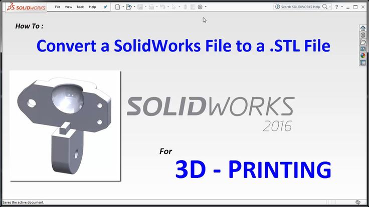 Typically you should use the ‘fine’ option with models from SOLIDWORKS, but 3D printing a few benchmark SOLIDWORKS models with different STL settings will determine the best settings for your machine.
New Method: Using GrabCAD Print
As I mentioned earlier a new method of 3D printing SOLIDWORKS files is by using GrabCAD Print. Which is a new FREE cloud-based solution that brings connectivity and accessibility to 3D printing. GrabCAD Print was only recently released and is still in beta as of writing this article.
The traditional workflow for 3D printing with STL files is fine if you have been using your 3D printer and 3D printing software for a while. But GrabCAD Print has recognized that this 3D printing process can be overly complicated as shown in the diagram below:
Traditional 3D Print Workflow
GrabCAD Print simplifies the process so you don’t need to create an STL file, allowing your team to get quality prints faster.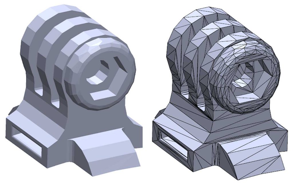
GrabCAD Print Workflow
Watch the video below to learn more about the new software:
GrabCAD Print your SOLIDWORKS files
The new process is pretty simple, download and activate GrabCAD Print. Then in GrabCAD Print select File > Insert File and choose your SOLIDWORKS part file. No need to save/export an STL file. SOLIDWORKS 3D printing is now much easier.
GrabCAD Print SOLIDWORKS File
A smooth SOLIDWORKS 3D printing workflow
With GRABCAD Print you can get the 3D printed parts you want, obstacle-free.
- Print directly from CAD: GrabCAD Print allows you to print directly from your favorite professional CAD formats, saving hours of time usually spent converting and fixing STL files.

- Get started fast: Lean on smart default settings, tooltips, and notifications to guide you through a seamless printing process.
- See what you’re making: Work with detailed views of your model, tray, and slice preview so you can make necessary adjustments before going to print.
GrabCAD Print Preparation
Get more from your 3D printer
Optimize your resources with a management view of all printers and jobs.
- Organize print queues: Maximize print scheduling based on machine availability, estimated job duration, and other key considerations.
- Monitor material levels: Know how much material remains for each printer so you can plan and budget.
- Stay up to date: Notifications let you know when your print is complete (or if an error has occurred) so you can act accordingly.
GrabCAD Print Schedule
3D Print from anywhere
Let anyone on your team experience the benefits of 3D printing.
- Print from any device: GrabCAD Print is cloud-connected so you can access it directly from any browser on your device of choice.
- Schedule and monitor remotely: Access and print to any supported printer in your company, even if it’s in a different geographic location.
- Minimal training required: A straightforward interface makes professional 3D printing as easy as loading a part and clicking print.
Give GrabCAD Print a try
GrabCAD print is currently in beta, but you can sign up for free at the GrabCAD website.
Note that GrabCAD Print currently supports the following Stratasys 3D printers: uPrint SE, uPrint SE Plus (both uPrint machines are on SALE at the moment) Fortus 250mc, Dimension Elite, Dimension 1200es (SST & BST), with more coming soon.
Of course if you want to learn more about SOLIDWORKS 3D printing then you should plan to attend our 1 day 3D Printing Essentials training course.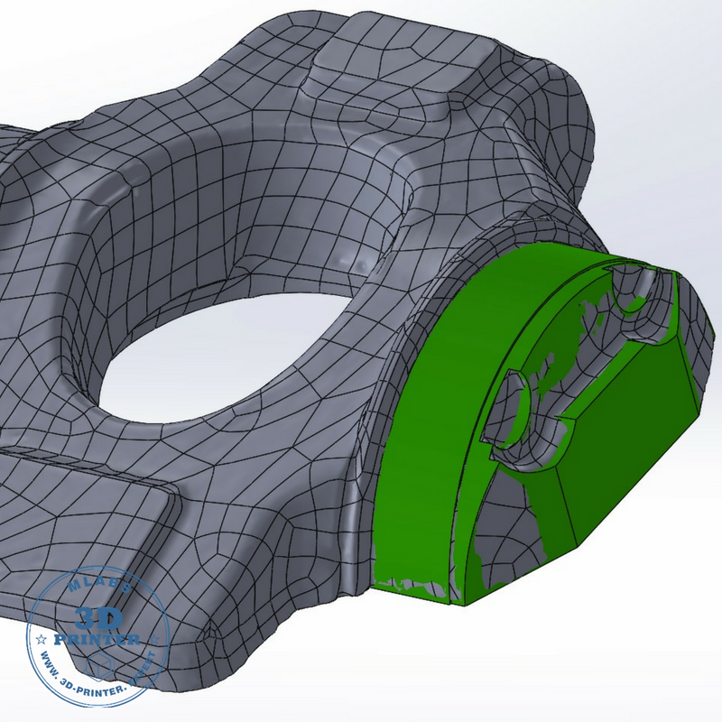 The course will teach you how to optimize your CAD files and 3D print your SOLIDWORKS models more cost effectively.
8 most common 3D file formats
3DPrintStory 3D printing process 8 most common 3D file formats
There are different formats for storing information about 3D models. Surely you have heard about the most popular ones like: STL, OBJ, FBX, COLLADA, etc. They are widely used in 3D printing, video games, film, architecture, medicine, construction and education. At the same time, each of the listed areas has its most popular formats, which were formed due to historical or practical reasons. In the article below, we will look at the various file formats of 3D models and dwell in more detail on the 8 most popular today.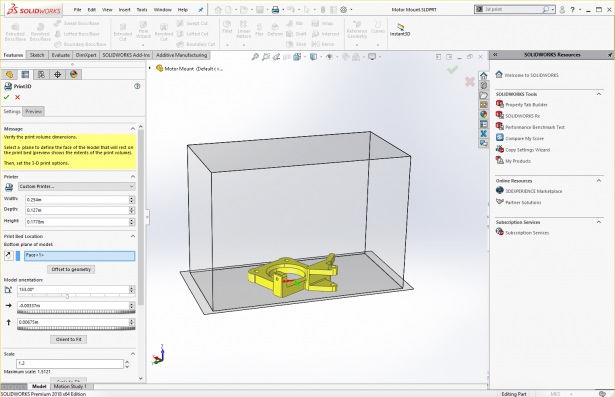
What is the 3D file format?
The main purpose of a 3D file is to store information about a 3D model in the form of a plain text or binary file. In essence, they encode information about the geometry, appearance, scene, and animation of a 3D model.
The geometry of a model describes its shape. Appearance includes colors, textures, material, etc. A scene refers to the location of light sources, cameras, and peripheral objects. Well, animation characterizes the movement of a 3D model.
However, not all 3D file formats store all of this information. For example, the STL format stores only information about the geometry and ignores the rest of the data. On the other hand, COLLADA stores all this data.
STL and COLLADA are just two of the many formats that are used in practice. Today there are more than 100 3D file formats!
How many 3D file formats are there?
There are hundreds of 3D file formats. Why are there so many? Mainly due to the fact that each developer of CAD software (for example, AutoDesk or Blender) has its own file format optimized specifically for their software. So if you are using AutoCad you will most likely be working with DWG files, and if you are using Blender you will be working with BLEND files.
Native 3D file formats are a problem...
Suppose you are using AutoCad (an AutoDesk product) and your friend is using Blender. And let's say you want to share your 3D model with a friend.
And here it turns out that everything is not as simple as we would like ... Your AutoCad outputs a DWG file, since this is its "native" format. But Blender (your friend's software) only works with BLEND files. That is, you will not be able to work on the same 3D model together.
Universal 3D file formats solve the problem
Universal or open source formats are used to solve the compatibility problem. And of course, these formats have become very popular.
The two most popular universal formats are STL (.STL extension) and COLLADA (.DAE extension). They are very widely used to exchange 3D medal data between CAD programs.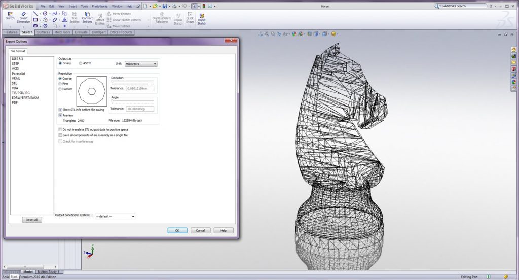 If you want to share your 3D model, you can convert the DWG file to COLLADA format - this process is called "export". Your friend takes this COLLADA file and imports it into Blender, where the COLLADA file is converted into the native BLEND format. Thus, you can use different CAD programs and still exchange data.
Proprietary and generic formats are the main fork in the world of 3D file formats. To date, most 3D modeling software has the ability to read and write popular universal formats. In addition, most programs also support the ability to work with formats from individual vendors that have become so common that they simply cannot be ignored. It is these proprietary and universal formats that we will consider below.
The table below summarizes the 8 most popular 3D file formats and their types.
before the end to the detailed. Let's deal with the important points that will help you choose the right format for your project.
General characteristics of different 3D file formats
We have already mentioned most of the characteristics above.
3D Model Geometry Encoding
Each 3D model has a unique geometry and this geometry encoding is the basis of any 3D model file format.
There are three principal methods for encoding surface geometry, each with its own advantages and disadvantages. These are approximate mesh, precise mesh, and constructive solid geometry (CSG).
Approximate mesh
During this encoding method, the surface of the 3D model is covered with a mesh of small imaginary polygons. Triangles are the most commonly used. The file saves the vertices and normal vectors to the sides of the triangles. Thanks to this, it is possible to accurately display the surface geometry of a 3D model.
Triangles approximate smooth surface geometry.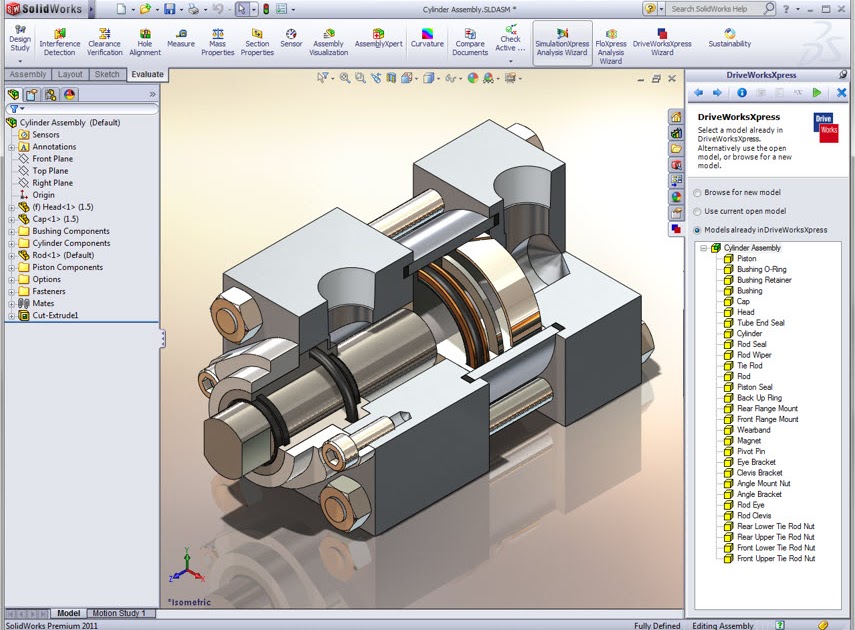 Hence the name - approximating grid. The smaller the size of the triangles, the better the approximation. At the same time, the smaller the triangles, the more they are needed to cover the surface and, accordingly, more data about vertices and normals is stored in the source file. That is, the better the approximation, the larger the file size of the 3D model.
3D files that use approximation are great for tasks where there are no high requirements for 3D model resolution. Since 3D printers have certain limitations in resolution, it is in them that such 3D files are widely used. The most popular 3D model format for 3D printing - STL - belongs to this type.
Fine mesh
https://all3dp.com/3d-file-format-3d-files-3d-printer-3d-cad-vrml-stl-obj/
Types of files for 3D modeling and 3D printing
3D models
- STL
- OBJ
- STEP
- Engineering software
- Art software
Almost everyone knows what types of files are used to save images: PNG, JPG, BMP, TIFF and others. But what about volume models? It would seem that we are adding a third dimension, but the file size is often smaller than even the image of the same model. In this article, we will tell you everything you need to know about files for storing models and even more: conversion methods, features of each type of file, and the file format for 3D printing.
3D model storage features
Unlike images, the voxel (voxel - volumetric pixel) storage method has not taken root in the world of 3D models. Only a few craftsmen use it when creating games or in scientific research. This is due to the history of the emergence of three-dimensional graphics: unlike the appearance of photography, three-dimensional graphics were originally created on a computer, and were used for animation. Voxels are much more difficult to animate, so they began to use the polygon storage method instead: the entire model consists of many polygons - triangles that have three points. It's like creating sculptures out of paper - by putting together a lot of flat pieces, you can get something voluminous and even smooth.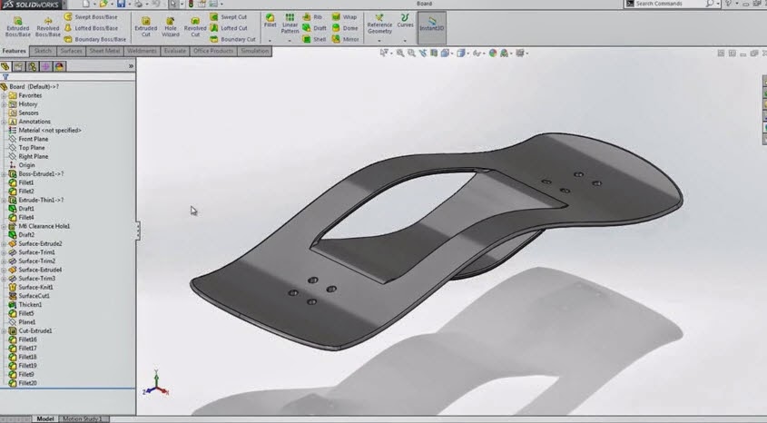
Dolphin Polygon Model
Although this method of saving as polygons cannot be called raster, these methods have much in common: the impossibility of increasing the quality, the direct relationship between the quality and file weight, ease of editing. This is the most practical format for saving and using models in 3D printing, but not the only one. Next, we will look at the most popular formats for storing 3D models.
Universal 3D Model File Formats
In fact, there are as many different methods for storing 3D models as there are for storing photos and videos. But there are also universal formats that, although with some restrictions, can be opened in almost any program.
STL
Contrary to misconceptions, STL was not originally intended for artistic modeling. It was developed by the Albert Consulting Group and was intended for an early 3D printing method - stereolithography.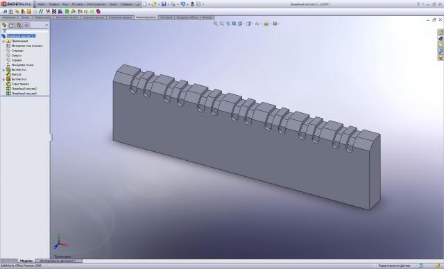 Hence the name of the file - STereoLithography. After some time, the company openly published the format and since then it has gained immense popularity.
The STL format is widely used due to the simplicity of its structure: polygons (facets) and their normals. The former are needed to set the surface, and the latter to indicate where the outer side of the polygon is located. Therefore, this format can be considered the most universal.
Comparison of CAD model and STL model
Due to the fact that the model is defined using many triangles, it is impossible to accurately define curved surfaces, because this would require an infinite number of triangles, and therefore an infinite data store. But when used in 3D printing, this minus is not so important, since the accuracy specified using triangles is higher than the printing accuracy.
OBJ
This format is very similar to STL, but differs in the ability to apply textures, set the material and store other information.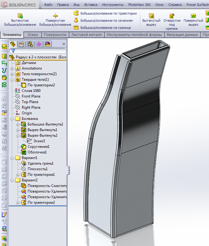 Therefore, OBJ can be called an extended version of STL and is mainly intended for artistic modeling programs such as Blender, Autodesk Maya, 3Ds Max, Meshlab and others.
Processing an OBJ model in Blender
STEP
Now we are moving on to the engineering side of 3D modeling, because STEP is the only format that can be opened in any engineering modeling program and freely edited with the tools built into the program. STEP was originally developed as a world standard format for storing products on a computer, and was intended for a complete development cycle of a part. That is why all serious engineering modeling and physical simulation programs can work with this format. A distinctive feature of STEP is its high accuracy: the model is created with tools that allow you to set curves using formulas. Therefore, the precision in this format is infinite: no matter how much you increase it, the curved line will remain a curve, and will not become a lot of straight lines.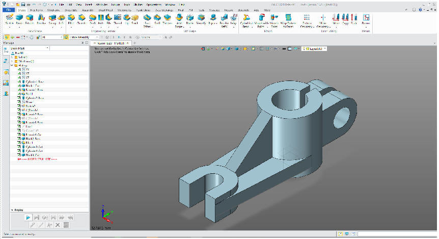
Creating a model in CAD SolidWorks
To create models in STEP format, CAD (Computer-Aided Design) is used. Thanks to the ISO standard, all CAD programs can work in this format. But not all data is freely transferred from one program to another via STEP. For us, the most important thing is the transfer of model geometry, and simulations, material and other data that the STEP format does not store are of secondary importance.
Proprietary formats
This category includes file formats that can only be opened in one program - in which the files were created. They are intended only for storing projects, often they cannot be used in 3D printing. An exception is the Ultimaker Cura slicer, which has the ability to add plug-ins that allow you to open files of programs such as Inventor, Siemens NX, Solidworks and others directly from the slicer.
Engineering programs
As mentioned earlier, these programs are called CAD.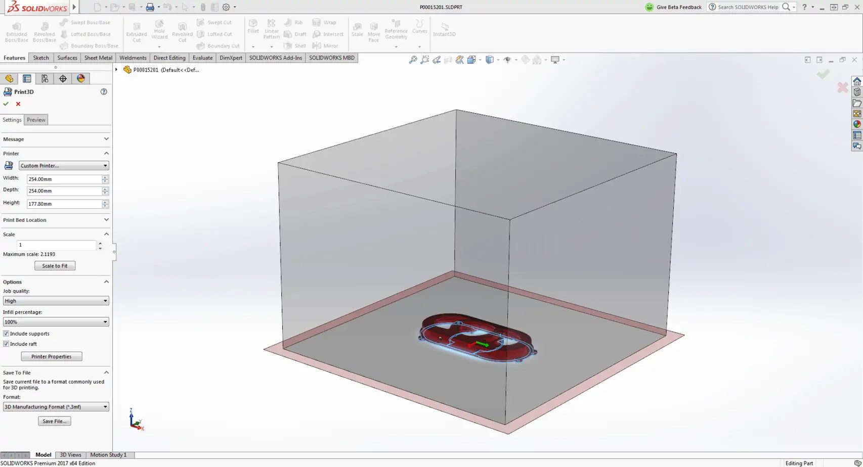 Since this software is often intended for production, they also have a common file format (STEP). Some programs, often produced by one company, allow you to work in a common ecosystem. For example, in many of Autodesk's engineering software, format compatibility can be found: Fusion 360 can open a file created in Inventor. But with this method of opening, some information about the product will still be lost, for example, information about the physical simulations performed. Therefore, if the part is not developed to the end, you should not move it between different programs.
Art programs
This category includes programs created for visualization: animation, special effects, creation of figures and models for video games. Unlike the previous case, chaos reigns in artistic modeling programs. Each program has its own format, and the general STL format limits the functionality of each program to the simplest tools. But this is enough to create models that will later be printed on a 3D printer, since only the geometry of the model is important.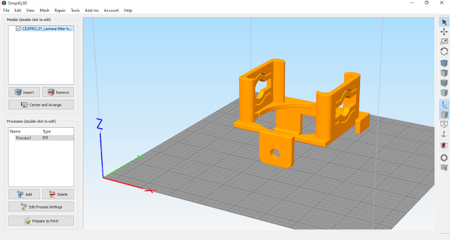
Gcode - format for 3D printing
Actually Gcode is more than just a file format. It is a separate programming language. But instead of executing commands by a computer, commands in this language are executed by a 3D printer. Initially, this language was developed for complex CNC machines, and a 3D printer is one of the simplest representatives of this type of device. Unlike previous formats, gcode can be easily edited manually, thereby giving commands to the printer directly, bypassing the computer. With this, you can create macros that make it easier to work with a 3D printer. You can read more about working with the gcode language and creating macros in an article on our website.
3D model file format conversion
If you have a need to move the model between programs for 3D modeling, then you should determine in which group the program is from where and where you want to move the model. If you are transferring it from one CAD program to another, then it is best to use the STEP format so as not to limit the number of tools for further modeling.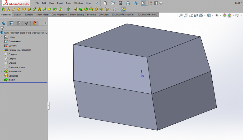 In all other cases, the only option is the STL format, which some CAD systems can recognize and in which art programs can save the model. It should be taken into account that when transferring a model from an art program to CAD, each polygon is transferred as a separate surface, so working with STL files in engineering programs can cause difficulties both in processing and in simple viewing of the model. This is due to the principles of CAD: it performs the processing of each surface separately, and the more surfaces, the more calculations need to be performed for one operation.
Tip: if the quality of the model is not so important when transferring a model from an artistic modeling program to CAD, then it is better to reduce the number of polygons as much as possible. This reduces the load on the computer and increases the speed when processing the model in CAD.
#Useful
Expert in the field of additive and subtractive technologies, 3D equipment and CNC machines with over 10 years of experience.


