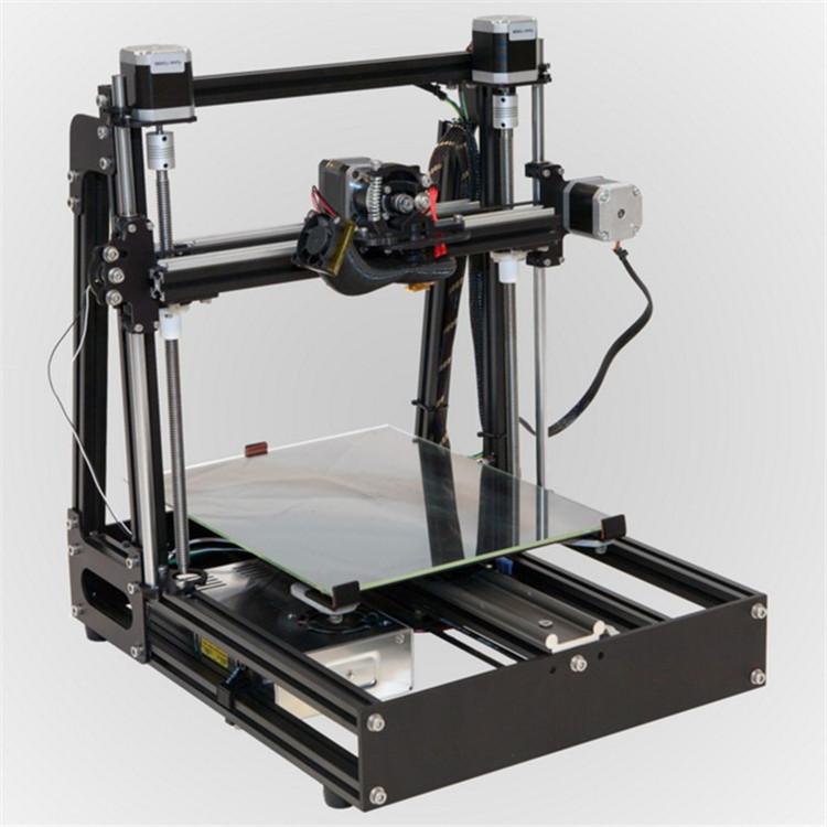
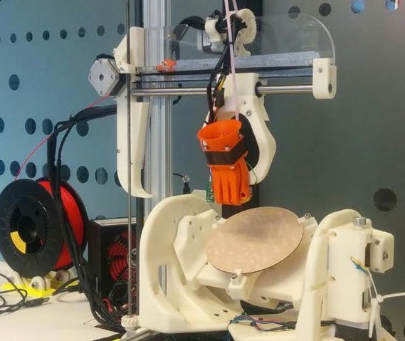
3D printer x axis drift
4 Ways How to Fix Z-Axis Falling/Slipping Down, Dropping or Loose – 3D Printerly
I went through a long period of great 3D printing with no issues, but then I started to experience my Z-axis starting to slip down and slowly fall while it was raised up. I couldn’t figure out why it was dropping like this, so I went to try and figure this out.
To fix your Z-axis slipping down, you should try tightening your eccentric nuts that hold the X-gantry to the Z-axis. You should also look towards fixing binding issues on your 3D printer by loosening and tightening the right screws. Lubrication works well for improving movements in your printer.
Keep on reading through this article for more in-depth information about fixing your Z-axis slipping or falling during the printing process.
Why Does Your Z-Axis Keep Falling or Slipping on Your 3D Printer?
There are instances when the Z-axis falls or slowly slips down on the print bed, often in the middle of printing, resulting in a ruined print. It has now become a common issue among 3D printing enthusiasts and creators.
The issue of your Z-axis falling can arise from quite a few issues, but the majority of the problem comes down to nuts and screws being too loose.
The function of Z-axis is to control the up and down movement of the printer’s nozzle. This is carried out by a long twisting screw known as the lead screw.
A binding of your Z-axis nuts with the leadscrew and 3D printer can definitely cause this dropping of your Z-axis, meaning your motor finds it harder to lift the Z-axis all the way through.
- Loose eccentric nuts
- Binding of your 3D printer Z-axis and lead screw
- Bad lubrication of your 3D printer
- Z-coupler and other screws not maintained
How to Fix Your Falling or Slipping Z-Axis On Your 3D Printer
1. Tighten the Eccentric Nuts
One of the simpler fixes for your Z-axis slipping or falling is to tighten the eccentric nut. This is the nut that is attached to the inner sides of the Z-axis, attached near the belt going across the X-axis.
You should see two eccentric nuts on both sides of the Z-axis. When I went through this issue, I tried all sorts of things with the lead screw and putting it all back together again, but it didn’t work.
When I finally tightened the eccentric nut along the Z-axis, my Ender 3’s Z-axis no longer slipped like before.
There is a single wheel on each of the Z-axis. Each wheel consists of an eccentric nut that is used for tension adjustment. You need to turn this nut with the help of a wrench until you are able to move the wheel smoothly.
What it does it tighten any gaps between the wheels and your printer’s frame. You’ll need a wrench that fits the size, but the wrench that comes with your 3D printer is usually smaller. I managed to use an adjustable wrench to get this tightened.
Note that the wheels shouldn’t rotate freely but should touch the extrusion just enough to keep the gantry straight.
When you are experiencing this problem, you should be able to turn the wheels and feel a “looseness” in some of them. Once you’ve tightened the eccentric nuts enough, they should be connected to the frame nicely.
2. Fix Binding Issues in Z-Axis
Another issue that can cause your Z-axis to fall comes from binding from your printer.
One user who fixed their original issue of the Z-axis falling down by tightening the eccentric nut, then found another issue where when auto-homing their 3D printer, the last motion of moving down stalled and wouldn’t move at all.
In order to fix this issue of binding, the user loosened the two screws for the brass lead screw nuts. You don’t want to loosen this so much that there is vertical play in this section, but loose enough that you can slightly feel some side-to-side play.
When this brass lead screw nut is too tight, it causes that binding which leads to restricted movements.
Depending on what 3D printer you have, there may be a higher likelihood that you experience these kinds of problems.
One issue with the Ender 3 is related to the plastic mount that holds the Z-motor in place.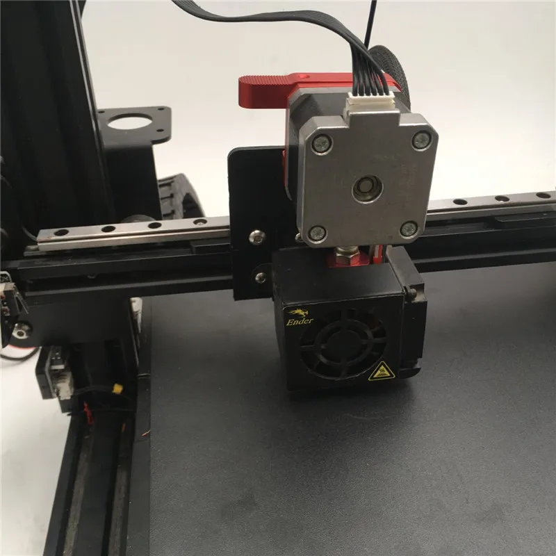 When you tighten the screws, what it does is actually turns the motor closer towards the vertical frame, leading to a binding of the leadscrew.
A test you can do is disconnecting your Z-stepper motor cable, lifting your X-gantry to the top of your 3D printer, then from there you should be able to push the gantry easily from top to bottom without it stalling.
If you do find there is some binding, you want to check that the related screws aren’t too tight.
Another thing I’d recommend is to shim the motor for a quicker fix. A popular Z-motor spacer/shim you can get on Thingiverse is the Ender 3 Z-Motor Spacer from Supavitax.
It provides support for the Z-motor to give it better alignment to prevent your leadscrew from binding.
A more solid fix for this issue is to print yourself a better mount for your Z-motor. This Ender 3 Adjustable Z Stepper Mount that you can find on Thingiverse is a great solution.
3. Lubricate Your Z-Axis
If you find that your Z-axis leadscrew is properly installed and is not binding, then you should try lubricating your 3D printer, especially around the Z-axis.
This can be as simple as using a lubricant PTFE spray or using a popular lubricant like Super Lube Synthetic Oil with PTFE from Amazon.
4. Tighten Your Z-Coupler & Screws
Another fix this works for some people is tightening your coupler so that it is securely fixed onto the leadscrew. You have the two screws for the coupler itself that you would’ve tightened during your initial assembly, so double-check those.
There are also more screws that are related to the Z-motor which are shown in the picture below. Tighten up these screws a little, so they aren’t loose.
Once you’ve implemented these four fixes, you should have a Z-axis which stays in place, especially while the motor is turned on. I’ve also heard of issues regarding faulty wiring on the Z-axis, but this doesn’t come up very often.
Layer Shifting
Layer Shifting
Most 3D printers use an open-loop control system, which is a fancy way to say that they have no feedback about the actual location of the toolhead. The printer simply attempts to move the toolhead to a specific location, and hopes that it gets there. In most cases, this works fine because the stepper motors that drive the printer are quite powerful, and there are no significant loads to prevent the toolhead from moving. However, if something does go wrong, the printer would have no way to detect this. For example, if you happened to bump into your printer while it was printing, you might cause the toolhead to move to a new position. The machine has no feedback to detect this, so it would just keep printing as if nothing had happened. If you notice misaligned layers in your print, it is usually due to one of the causes below. Unfortunately, once these errors occur, the printer has no way to detect and fix the problem, so we will explain how to resolve these issues below.
Common Solutions
Toolhead is moving too fast
If you are printing at a very high speed, the motors for your 3D printer may struggle to keep up. If you attempt to move the printer faster than the motors can handle, you will typically hear a clicking sound as the motor fails to achieve the desired position. If this happens, the remainder of the print will be misaligned with everything that was printed before it. If you feel that your printer may be moving too fast, try to reduce the printing speed by 50% to see if it helps. To do this, click “Edit Process Settings” and select the Speeds tab. Adjust both the “Default Printing Speed” and the “X/Y Axis Movement Speed.” The default printing speed controls the speed of any movements where the extruder is actively extruding plastic. The X/Y axis movement speed controls the speed of rapid movements where no plastic is being extruded. If either of those speeds are too high, it can cause shifting to occur. If you are comfortable adjusting more advanced settings, you may also want to consider lowering the acceleration settings in your printer’s firmware to provide a more gradual speed up and slow down.
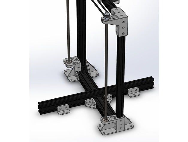
Mechanical or Electrical Issues
If the layer misalignment continues, even after reducing your print speed, then it is likely due to mechanical or electrical issues with the printer. For example, most 3D printers use belts that allow the motors to control the position of the toolhead. The belts are typically made of a rubber material and reinforced with some type of fiber to provide additional strength. Over time, these belts may stretch, which can impact the belt tension that is used to position the toolhead. If the tension becomes too loose, the belt may slip on top of the drive pulley, which means the pulley is rotating, but the belt is not moving. If the belt was originally installed too tight, this can also cause issues. An overtightened belt can create excess friction in the bearings that will prevent the motors from spinning. Ideal assembly requires a belt that is somewhat tight to prevent slipping, but not too tight to where the system is unable to rotate. If you start noticing issues with misaligned layers, you should verify that your belts all have the appropriate tension, and none appear to be too loose or too tight. If you think there may be a problem, please consult the printer manufacturer for instructions on how to adjust the belt tension.
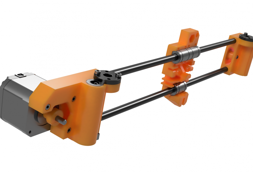
Many 3D printers also include a series of belts that are driven by pulleys attached to a stepper motor shaft using a small set-screw (otherwise known as a grub screw). These set-screws anchor the pulley to the shaft of the motor so that the two items spin together. However, if the set-screw loosens, the pulley will no longer rotate together with the motor shaft. This means that the motor may be spinning, but the pulley and belts are not moving. When this happens, the toolhead does not get to the desired location, which can impact the alignment of all future layers of the print. So if layer misalignment is a reoccurring problem, you should verify that all of the motor fasteners are properly tightened.
There are also several other common electrical issues that can cause the motors to lose their position. For example, if there is not enough electrical current getting to the motors, they won’t have enough power to spin. It is also possible that the motor driver electronics could overheat, which causes the motors to stop spinning temporarily until the electronics cool down. While this is not an exhaustive list, it provides a few ideas for common electrical and mechanical causes that you may want to check if layer shifting is a persistent problem.
Related Topics
X-axis flex and sag on Ender-3. How to eliminate?
Important first steps (partial disassembly of the printer). Straighten both Z-axes. Adjust eccentric nuts. Tighten the bolts that secure the roller assemblies. Conclusion.
The huge community of Ender-3 printer users often has questions about how to build, set up and operate this popular beginner 3D printer.
We decided to write a post-answer to one of the common questions: X-axis slack on Ender 3. How to fix it?
Let's get started!
Problem:
I bought my Ender 3 just a few weeks ago and after reassembly it seemed to work fine, but I noticed that I was having trouble calibrating my table.
I started printing after calibration, but for some reason the nozzle always burrowed into the surface of the table on the right side.
I decided to re-calibrate the platform, and it turned out that the printer on the right side was not calibrated, although everything was fine before starting printing.
I noticed that after starting printing, something changed dramatically and the nozzle changed its position: sometimes too close to the table, sometimes too far.
I figured it was due to slack in the x-axis, but sometimes it sagged and sometimes it didn't, so it was almost impossible to level the table.
On the Internet, you can find a considerable amount of advice on how to fix this problem. We have chosen the one that works best.
Important first steps (partial disassembly of the printer).
- Remove the plastic spool, otherwise it will become tangled and uncomfortable.
- Use the large hex wrench included with the 3D printer assembly kit to remove the screws on the top rail.

- Next, be sure to disconnect the cables connected to the E extruder motor, the motor, and the X axis limit switch.
- Using a smaller hex wrench, loosen the screw on the sleeve that holds the z-axis trapezoid screw, and then completely remove it by turning it counterclockwise and set it aside for now.
Straighten both Z-axes.
Make sure the Z-axes are not rotated or misaligned with the printer frame.
The misalignment of the axles puts pressure on the rollers and they cannot move freely up and down the profiles, causing damage over time.
So, here's how to solve both of these problems:
- Place the printer on its left side (display side up to avoid the weight of the printer).
- Slightly loosen the screws on the bottom of the printer holding the Z axis in place. There is no need to completely unscrew them, just loosen them so that you can rotate or jiggle the Z axis.
- Rotate the Z axis until it is properly aligned and, holding it in place with one hand, tighten the screws with the hex wrench with the other hand.
If you first disconnect the power supply, then it will be much easier for you to align the axis, because it will not interfere with you.
- Do the same with the other Z axis, making sure the frame is level and as square as possible.
- Now it's time to put the X axis back in place to check if the slack is gone and if the rollers can move freely up and down the profiles. To check if the problem is solved, screw the top guide so that the countersunk holes are facing up, and then move the X-axis up and down.
In some cases the above manipulations are sufficient and the rollers do not need to be calibrated. Unfortunately, this is not always the case, so let's move on to the next step.
Adjust the eccentric nuts.
The eccentric nut differs from the usual one in that the hole in the nut is offset to one side and when rotated, it moves the wheel / roller closer or further from the axle, and this allows you to adjust how tightly the entire assembly will cling to the axle.
If the nut is too tight, it will not be able to move up and down freely. On the other hand, if too loose, the entire roller assembly will shake and wobble.
To adjust the eccentrics you will need the wrench included in the assembly kit.
- Using the large side of the wrench, loosen the nut so that you can move the entire roller assembly freely.
- Then begin to tighten the nut until you feel that the roller assembly is tight against the axle. It should fit snugly, but not too tight (it's not easy to explain, but it's pretty easy to feel when you do it). You have to make some effort to scroll the video with two fingers.
- Once you're done with one side, do the same for the other side.
Move the X-axis up and down to make sure it moves smoothly, then lower it all the way down until you hear the Z-axis limit switch “click”, then move the axis up again, but lift it not in the middle, but on the right sides.
If the whole structure moves smoothly and the right side moves the same as the left side, then you did everything right!
You may have to take one more step to completely solve this problem and that is to tighten the bolts that hold the roller assemblies.
Tighten the bolts that secure the roller assemblies.
If you look at the frame that the extruder is attached to, there should be two screws in the middle that hold it to the X axis.
Check if they are slightly loose or you didn't level the structure during assembly.
Here's how to fix it:
Using one of the hex keys that came with the printer, loosen the two screws that secure the carriage to the X axis. Loosen the screw closest to the center of the printer just a little.
Using this internal screw as a reference point, slightly adjust the x-axis until it aligns correctly.
Tighten both screws until there is no play.
Keep in mind that in general, this is not the main culprit for X-axis slack, so you should focus on adjusting the eccentric nuts and axle offset first.
Conclusion.
X-axis slack will create a lot of problems and needs to be fixed. Luckily, it's not that hard and it will take you about 10 minutes for the printer to function properly.
You can start by adjusting the eccentric nuts without even disassembling the printer, but we highly recommend following the steps we have described as it is a very simple and effective method.
We hope this information was helpful!
Happy printing!
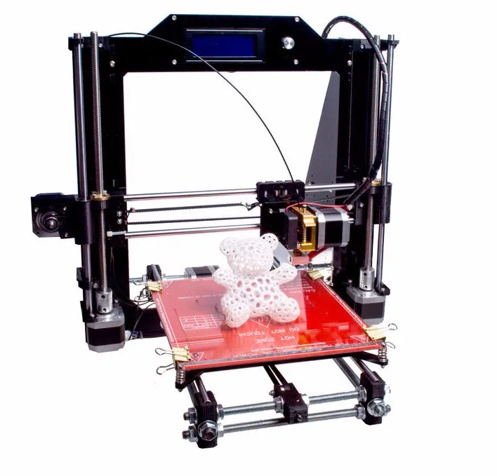
How to calibrate a 3D printer in 5 steps・Cults
The first 3D printer was developed in the 1980s by Charles W. Hull, but the technology only became popular in the early 2000s. Since then, 3D printing has come a long way and is used all over the world for personal and industrial applications.
3D printing enthusiasts will attest that it takes a long learning curve to make good use of this technology and related software. One of the hardest parts of this learning curve is machine calibration. Here we will cover the basic calibration procedure required for 3D printers. This article is written from the point of view of simple and reusable Printrbot and assumes that the user has a digital caliper, ruler, ribbon, and thread. If the reader does not use Printrbot simple and Repetier, then there is no problem, any combination of printer and software will do.
Open Repetier, connect the printer and select the manual tab. Select the toggle button with simple mode disabled and enter "M501" in GCode. Press the Enter key and scroll until you find a code that looks like "echo": M92 X__ Y__ Z___ E__.".
Pay special attention to this line of code, as it will be important in the future. to the side and place a piece of tape on the printer bed, parallel to where it will not move when you move the X axis. Mark the tape where the X axis currently points.
Using Repetier, instruct the printer to move the X axis starting at 70mm and make another mark at the end of the X axis. The printer just moved to where it thinks 70mm is. Now, using a caliper, measure the distance between the two marks to determine the actual travel distance.
A new M92 value needs to be found, using the current M92 value recorded in step 1. This can be achieved using the following equation. After calculating the new value M92 for the x-axis, it must be entered in the G-code.
New M92 value = desired travel/actual travel * actual M92 value.
The process of calculating the Y-axis is the same as calculating the M92 actual value for the Y-axis. Note where the Y-axis starts, enter a value for its offset, and note where the Y-axis ends. With a caliper, you can determine the actual distance travelled. Using the same equation, a new M92 value can be calculated and entered into GCode.
New M92 value = desired travel/actual travel * actual M92 value.
The Z axis is much easier to calculate with a ruler than with a caliper. To get started, simply specify the x, y, and z axes and position the ruler parallel to the plate. Select a point on the print shoulder along the Z axis and measure the distance from the printing plate to that point. Now, as before, enter a value for the x-axis offset and measure how much it has moved. Formula for determining the new value of M92 for the Z axis is slightly different from the other two.
Input measurement/actual measurement * Old M92 value = New M92 value.
Enter this value in the GCode for the Z axis.
This is the last item to check in the calibration process. To calibrate an extruder, determine how much filament comes out of the extruder. To begin, heat the hot end to the suggested temperature and make a mark on the thread about 3 cm from the entry point. Command the printer to extrude 10mm of filament and take a measurement to determine the distance between the two points. If the distance is 10 mm or any other value is entered, then the extruder is calibrated. Otherwise, a new value of E M9 must be calculated2 and enter it into GCode. This value can be found using the formula below.
Desired measurement/actual measurement * current M92 value = new M92 value.
Calibrating a 3D printer might seem like a daunting task at first, but it's not, all you're doing is figuring out if the motion you enter matches the actual motion.