Simulate 3d printing
Simulations in 3D printing | Hubs
Learn about the benefits and current state-of-the-art of 3D printing simulations. This article describes why, what and how to use simulations in 3D printing and gives tips to help you get started.
Introduction
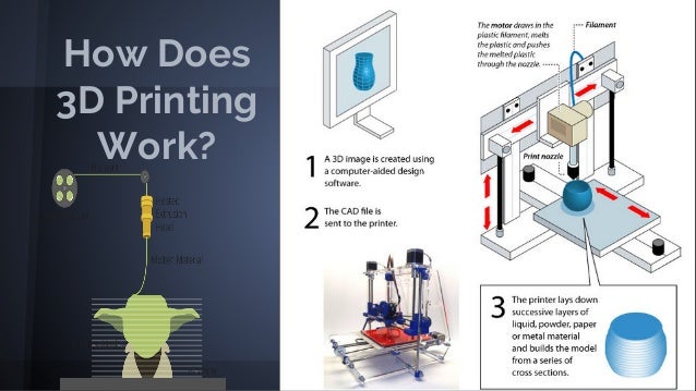
Simulating the fabrication process is slowly becoming part of the 3D Printing workflow. 3D printing simulations help to understand and visualize the complex thermo-mechanical phenomena taking place during manufacturing, resulting in the production of high-quality, high-accuracy parts.
This is especially important for high-value components fabricated using state-of-the-art 3D printing process, where design iterations (discarding a defective print) are very expensive in terms of both material cost and manufacturing time.
Simulations of the 3D printing process should not to be confused with the more common mechanical FEA simulations: The latter helps evaluate the mechanical performance of a part under certain conditions related to its function (load, deformation, temperature etc), while the former helps predict the result of the 3D printing manufacturing process, layer-by-layer and under certain process parameters.
In this article we first present the main benefits of simulating each of the 3D printing processes and then we take a closer look at the details of running a successful simulation, giving some handy tips to get you started.
Why use simulations in 3D printing?
Simulating the 3D printing process is very valuable, because it helps to:
Avoid print failures and parts rejected for geometric issues, saving time and reducing overall cost.
Evaluate the risk of production and give pointers to mitigate the probability of failure.
Understand the physics of the manufacturing process.
Predict the microstructural characteristics of the end part.
Optimize production to improve manufacturing speed, reduce post-processing operations or improve accuracy by reducing the part and support deformation.
You can perform the simulation before or after generating the support structures:
Before support generation, simulation results help identify critical areas of significant deformation or internal stress during manufacturing. The designer can then add adapted support structures to minimize the deformation, change the print orientation to change the areas of heat accumulation or modify the geometry of the 3D model to improve the quality of the end result.
After support generation, simulations help minimize the risk of production failure (for example due to recoater interference), ensure that the dimensions of the final part lie within a specified tolerance range and evaluate the impact of different print parameters (for example, by comparing parameters optimised for production versus parameters optimised for accuracy).
In both cases, simulations aid in reducing the risk associated with high-value manufacturing and to improve the productivity of high-volume 3D printing, saving weeks of production time and thousands of dollars in development and production costs.
Which 3D printing processes to simulate?
Simulations are most relevant for high-value and high-precision 3D printing. Moreover, the most popular contemporary 3D printing simulation packages are based on metal welding simulation solvers. Thus simulations are more commonly used with metal 3D printing.
However, all main 3D printing processes can be simulated and here is why:
SLM/DMLS: SLM and DMLS are the oldest and most mature technologies among metal 3D printing processes and, therefore, many software packages focus primarily on them. Because the fusion temperatures of metals are higher than the polymer sintering temperatures, the thermo-mechanical constraints in SLM/DMLS parts are most important.
EBM: EBM is a more recent metal 3D printing technology compared to SLM/DMLS and only a few software packages provide solutions for it. Simulations in EBM can help identify the heat accumulation regions generated from the electron beam.
FDM: The main issue with FDM is warping, which occurs due to differential cooling of the extruded thermoplastic material. Simulation can help check whether the part needs to be redesigned or whether a brim should be added to increase the adhesion to the platform.
SLA/DLP: In SLA and DLP the main issue is curling, which is similar to warping. Not many software solution exist to simulate the SLA process at the moment.
SLS: In SLS, support structures are not required, but zones of thermal accumulation can appear in the build, resulting in poor surface smoothness or warping. Simulation can help identify these areas.
Simulation outputs & results
Temperature distribution
The gradient of temperature is the root cause of all the mechanical phenomena occurring during a build.
The temperature gradient can sometimes be computed alone, without any mechanical deformation. It is usually quicker than a full simulation and solving the heat accumulation issues might at the same time solve the mechanical deformation problems.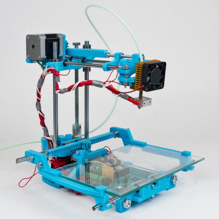
Temperature gradient distribution of a descretized model (SLM/DMLS) in Netfabb. Courtesy Poly-Shape
Deformation
Assuming that the true mechanical properties of the material are known, the deformation of the part during manufacture can be calculated.
The direction of the deformation are usually correct no matter what simulation parameters are used, but the amplitude of the deformation is closely dependent on the size of the simulation mesh: using a finer mesh will yield more precise results, but requires more time to run.
Deformation vectors of a model (SLM/DMLS) in Netfabb. Courtesy Poly-Shape
Recoater interference
In powder bed technologies (such as SLS and SLM/DMLS), if the deformation along the z-axis is larger than the layer thickness, the recoater can come in contact with the part, sweeping it away and causing a failure. In some simulation packages, you can define the height of the recoater tolerance and the software will warn you in case a deformation along the z-axis exceeds that threshold.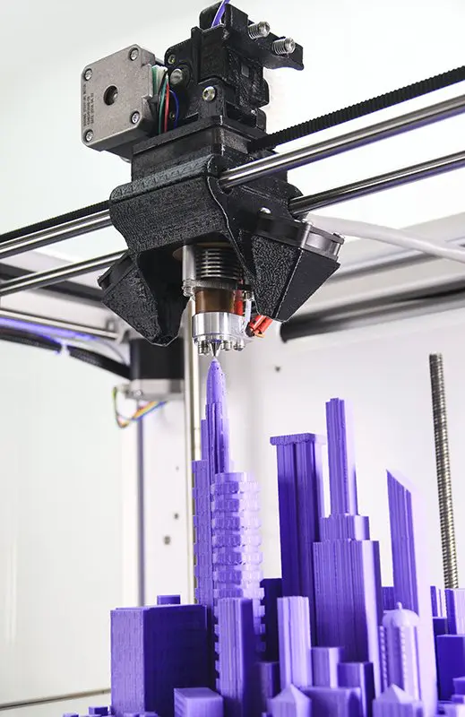
Post processing steps
The primary focus of the 3D printing simulation packages is the computation of thermo-mechanical phenomena occurring during the fabrication of a part. However, other problems can also appear in later steps of the manufacturing process.
During the detachment of the part from the build platform or the removal of the support structures, the residual stress from the manufacturing process can cause the part to deform. Heat treatments can help relieve the internal stress. Some simulation packages allow you to simulate these post-processing steps and help evaluate whether a heat treatment is necessary (or even effective).
List of simulation software
Discretization
The first step of a good simulation is the correct discretization of the part volume.
Unlike regular mechanical simulation, which uses conformal meshing with tetrahedrons, most 3D printing simulation software use voxelization. the 3D volume of the part is represented by small cubes (or voxels), in a similar way that a 2D image in a PC monitor is represented by square pixels.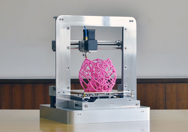 Using more meshing elements produce more precise results, but also increases significantly the simulation time. Finding the right balance is key.
For an initial simulation, it can be interesting to launch a first coarse simulation, with large voxels, in order to obtain “quick and dirty” results. Such a simulation should enable you to obtain in a matter of seconds or minutes the main deformation areas of your print. It will not cost you much and can help you decide if a more precise simulation (with smaller voxels) is necessary.
Material & print parameters
Once the part is discretized, you need to select the material properties. Defining the material properties is probably the most crucial step in the simulation process, as inaccurate data will produce wrong simulations results.
Most editors provide their own material library, which can be really helpful to get you started.
In both cases, they are probably not perfectly adapted for simulations. Every simulation software allows you to modify or create your own materials to generate the most accurate simulations.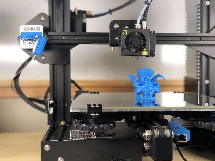 This requires expert material science knowledge to be done correctly and it is not recommended for inexperienced users.
Calibration
Some simulation software allows you to calibrate the material properties based on test specimens printed in a specific material and on a specific machine. This way, more precise material properties are identified, resulting in more accurate simulation results.
Key steps for a successful simulation
There are two types of simulation software: cloud based solvers and local solvers.
Cloud based solvers are usually faster than local solvers, as they are not restricted by the computational capabilities of your computer. However, some companies are reluctant to use cloud based solvers due to confidentiality issues, as data sent through the Internet could be more easily compromised. For most application this would not be an issue.
Here is a list of some of the most popular 3D printing simulation software:
| Software | Type | Supported Processes |
|---|---|---|
| Amphyon | Local | SLM/DMLS |
| Comsol | Local | SLM/DMLS, SLS, FDM |
| ESI | Local | SLM/DMLS |
| exaSIM | Cloud-based | SLM/DMLS |
| Netfabb | Local & Cloud-based | SLM/DMLS |
| Simufact | Local | SLM/DMLS, EBM |
| GeonX | Local | SLM/DMLS |
| EX Digimat-AM | Local | SLS, FDM |
Rules of Thumb
- Simulate before support generation to improve part geometry and to aid with the design of supports.
- Simulate after support generation to validate accuracy and to check for recoater interference.
- First run a quick simulation with large voxels to identify areas of larger deformation. Then refine the mesh to improve accuracy of the results.
- Simulate temperature without mechanical resolution to save time, as solving the heat accumulation issues might also solve mechanical deformation problems.
- Prefer cloud based simulation software for faster performance, but use local solvers if needed to comply with confidentiality policies.
Essential Bonus: Download for free the Design Rules for 3D printing poster in high-resolution, full of actionable guidelines for the 6 major 3D printing processes.
Ready to transform your CAD file into a custom part? Upload your designs for a free, instant quote.
Get an instant quoteAdditive Manufacturing & 3D Printing Simulation Software
Request a demo
ACCELERATE YOUR MANUFACTURING PROCESS
A COMPREHENSIVE SOLUTION CONVERGING DESIGN, SIMULATION, AND ADDITIVE MANUFACTURING
Gain insights through automated workflows to eliminate the risk of distorted or out of tolerance parts, and ensure high quality components.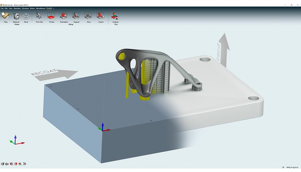
- Powder Bed Fusion
- Directed Energy Deposition
- Metal Sintering
- Workbench Connectivity
Additive Simulation
- What's New
- Additive Processes
- Products
- Capabilities
- Resources & Events
JULY 2022
What's New
Ansys 2022 R2 expands toolsets for Additive Manufacturing Users, streamlining your workflows between design, simulation, and manufacturing. Every Ansys Mechanical User can now identify and minimize the risk for build errors and ensure high-quality parts through process simulation for Metal Laser Powder Bed Fusion (LPBF), Directed Energy Deposition (DED), and Metal Binder Jet (MBJ).
- Workflow Improvements
- Automatic Distortion Compensation is the ability to optimize a distortion compensated model within a simple automated workflow, which improves first-time print success.
- Accuracy Enhancements
- Consolidating additive technologies include Laser Power Bed Fusion (LPBF) scan pattern effects in Workbench Additive. With the consolidation of additive technologies, all users can rapidly increase simulation fidelity, capturing localized strain variations in each deposition layer.
Speed Performance
- Introducing a Machine Learning (ML) model for predicting thermal strain can result in 10X time savings. Users can now easily explore the benefits of varying process setup parameters such as power, speed, and scan vector.

- Introducing a Machine Learning (ML) model for predicting thermal strain can result in 10X time savings. Users can now easily explore the benefits of varying process setup parameters such as power, speed, and scan vector.
Webinars
Additive Processes
Powder Bed Fusion (PBF)
What is it?
Powder Bed Fusion (PBF) is a metal additive manufacturing technology using a bed of powder with a source of heat to create metal parts.
How Ansys helps:
- Predict the part shape, distortion, and stresses before printing with distortion prediction & compensation capabilities
- Auto-generate supports, helping you predict maximum residual stresses that supports must withstand
- Melt pool, porosity & microstructure predictions for process parameter development
- Best-in-class material properties for powerful analytics to establish the process property relationships
- Structural and thermal analysis design validation
Directed Energy Deposition (DED)
What is it?
Directed Energy Deposition is a 3D manufacturing process combines metal feedstock and a laser to fabricate parts.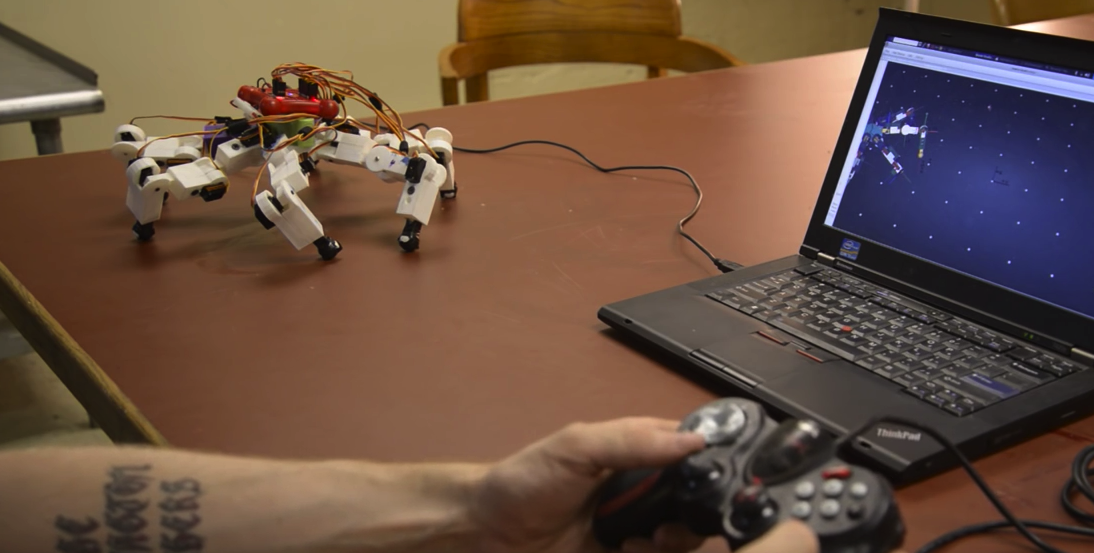
How Ansys helps
- Full part thermal mechanical process simulation
- Macro level temperature, deformation, strain and stress prediction
- Intelligent Gcode commands support
- Customizable fidelity-cost balance
- Non-planar baseplate compatibility
Metal Sintering
What is it?
Metal Sintering micro-welds powdered metals to form metal components.
How Ansys helps
- Predict shrinkage and bending before printing
- Auto-generate supports, helping you predict maximum residual stresses that supports must withstand
- Get insight into how parts will behave during a build and takes corrective steps to get the details right the first time
- Best-in-class material properties to ensure traceability of additive manufacturing data
- Check for distortion, stress, and strain regions, predict blade crash
Additive Products
Additive Suite
Additive Manufacturing
Additive Suite spans the entire workflow – from design for additive manufacturing (DfAM) through validation, print design, process simulation and exploration of materials.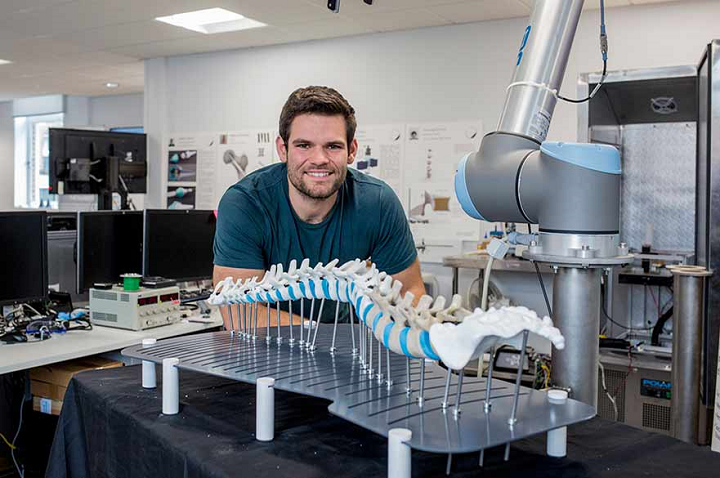
Additive Suite includes:
- Additive Prep
- Additive Print
- Additive Science
- Access to Workbench Additive
View Product
Additive Print
Additive Manufacturing
Choose parts correctly the first time on Metal AM Equipment with Additive Print, a standalone solution for Additive Manufacturing Process simulations.
- AM Process simulation tool for Powder-Bed Fusion Process
- Blade Crash Detection
- Stress and Strain Analysis
- Distortion predictions
- Ensure first-time right printed parts
View Product
GRANTA MI Enterprise
Materials
The leading system for materials information, GRANTA MI Enterprise allows you to develop and protect your materials, save time, drive innovation, cut costs and eliminate risk.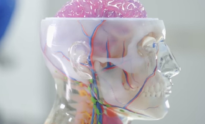
- Ensure traceability of additive manufacturing data
- Data includes powders, builds, machine parameters and more
- Provide Additive Manufacturing data to help optimize
View Product
Free Trial
Ansys Discovery
3D Design
Our innovative interface for 3D design engineers combines live physics simulation, high-fidelity results and direct modeling.
- Design for Additive Manufacturing (DfAM) tools
- Features live physics simulation
- Delivers fast high-fidelity results
- Explore multiphysics and multiple physics scenarios
- De-feature CAD models, extract fluid domains or simplify models for simulation
- Topology optimization speeds workflow
- Works with any CAD file
View Product
Capabilities
Ansys Additive Solutions, a comprehensive and scalable software solution, enables minimized risk while ensuring high-quality, certifiable parts.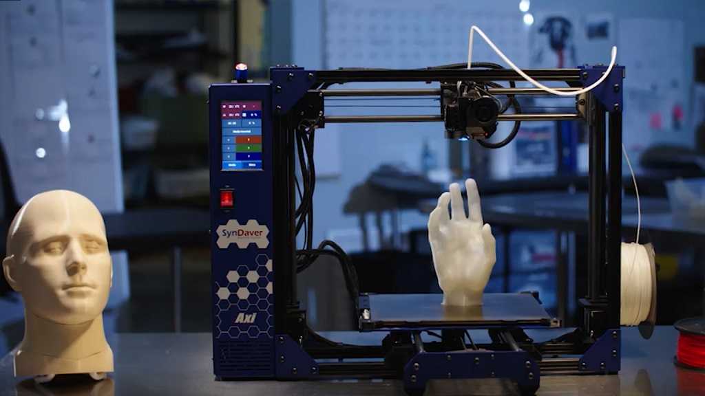
- Design for AM (DfAM)
- Build setup
- Process simulation
- Material analysis
- Data acquisition and management
- Part qualification
- CAD Modeling
- Topology Optimization
- Lattice and Light weighting
- STL file repair and geometry manipulation
- Part nesting and support generation
- Orientation guidance and wizards
- Metal AM process simulations
- Distortion compensation
- Build failure prediction
- Curated material property databases
- Grain morphology predictions
- Melt pool and porosity prediction
- Traceability and full control of AM data
- Consolidate, control and share AM data across organization
- Design validation
- Structural and thermal analysis
- Document control and certification
CASE STUDIES
WEBINARS
Imitation of wood texture in 3D printing.
 Papa Carlo Method
 In the past year, printouts made of wood-filled plastics were laid out from time to time. Here are a couple of interesting works:
These plastics are designed to imitate wood when printed. But printouts are still more like chipboard.
Very plausible end caps for a wooden staircase turned out by comrade eduardo:
Due to the alternation of temperature on different layers with a change in color, a texture was obtained that resembles the annual rings of a tree. nine0003
It turns out that in order for the printout to look like a real tree, you need plastic in two colors (light and dark annual rings). And it would be more logical to draw these annual rings in the model itself than to try to get them by changing the printing temperature.
We are trying to depict a product carved from wood. And why not take and draw, as plausibly as possible, a log with its structure of annual rings. And already from the log cut out any Pinocchio we need. This is, of course, a tortuous path, but it promises us an interesting result. nine0003
Let's start drawing in Solid Works. I looked a little at how the tree cuts look like:
And I started drawing my sketch:
When drawing, it is better to avoid splines and replace them with arcs, otherwise the program may start to desperately slow down.
From this sketch, extrude the boss along the path. We take a slightly curved line as a trajectory:
It would be possible, of course, to use an ordinary elongated boss, but then the pattern will turn out to be unnaturally straight when cut. nine0003
The result is a part of the log, consisting of light rings:
We extend the dark annual layers using the same boss along the path.
At the same time, we use the sketches of the profile and the trajectory from the previous boss (with light rings).
To do this, you need to make them available. You need to right-click on the thumbnails and select “display” (points):
When extruding the boss, select the areas not occupied by light layers. And an important point. You need to uncheck the "combine results" checkbox:
Otherwise, all layers will merge into a single cylinder.
Now we have the same log of light and dark layers, with each layer being a separate body:
Now we can cut any shape out of the log using cutouts.
If you use a regular elongated cutout, you can get a board and even make a sign on it:
Or a dice:
If you use a rotated cutout, you can get rotation figures:
In principle, you can create absolutely any figures using operations subtraction. nine0003
The woodgrain effect opens up a wide range of applications.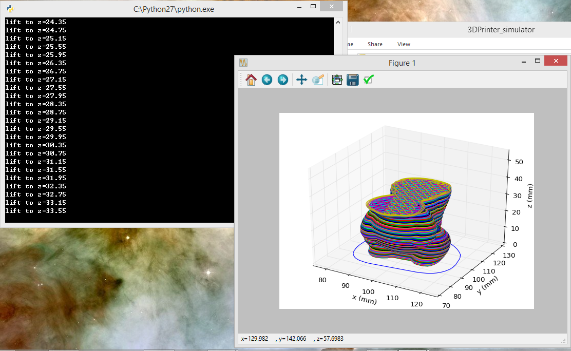 Similarly, you can create models for phone cases, various devices, and even inserts in car dashboards. And everything related to the car can be very promising in terms of modeling and printing to order. Some people love cars more than their wives.
But to print dual color models, you will need a dual print head printer with good print quality, such as the ULTIMAKER 3.
But the vast majority own printers with a single print head. Shouldn't it be applied already?
If you are not afraid of post-processing, then you can get by with an ordinary one-eyed Chinese.
I'll show you how:
Let's create something useful... For example, a handle for a door or for a checkpoint.
Like this (one rotated log cutout):
Now let's remove the dark annual rings (bodies) from the model and fill in the resulting voids at a distance of 1 mm from the surface (using a rotated boss):
Save in STL format, slice, print with supports (beige PLA REC):
Now fill the grooves with PLA juice from plastic of a different color.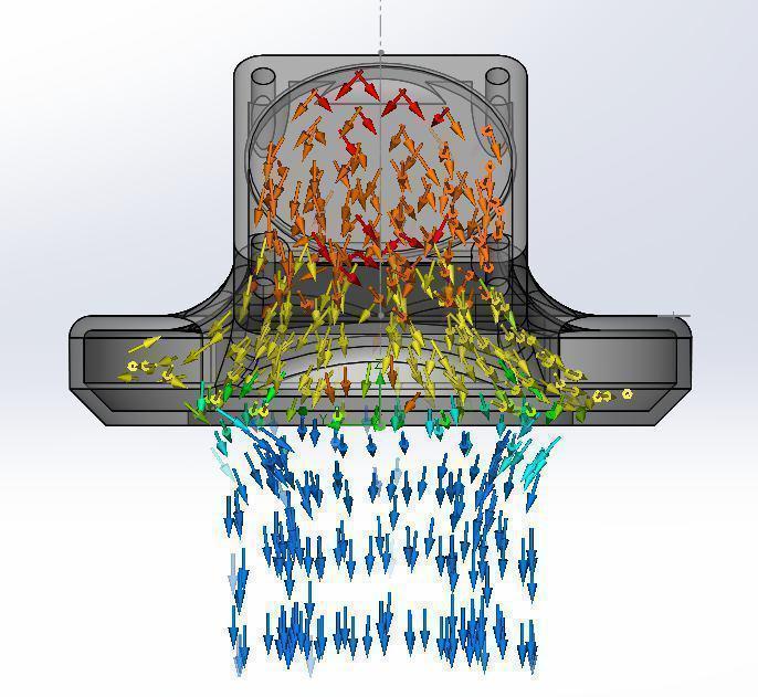 Personally, I smeared with a screwdriver. It is desirable to make the consistency thicker in order to reduce shrinkage after drying. Or we fuse plastic with a 3D pen. PLA juice has the advantage of being able to more accurately match colors by incorporating multiple colors of plastics into the solution. I came up with such a nightmare:
After the PLA juice dries, we grind off everything superfluous. For the convenience of grinding, I provided a socket for a bit for a nozzle on a screwdriver. Wet the surface with DXM with a brush to shine:
The result is certainly not ideal. Here you can also refine the model of the log itself for greater realism, add a varnish coating with the desired shade. Also, the use of wood-filled plastic would add naturalism. But in general, in my opinion, it turned out well. Something reminiscent of the texture of pine. By the way, PLA juice after solidification contains a lot of bubbles in the mass, which also adds a sense of porous structure.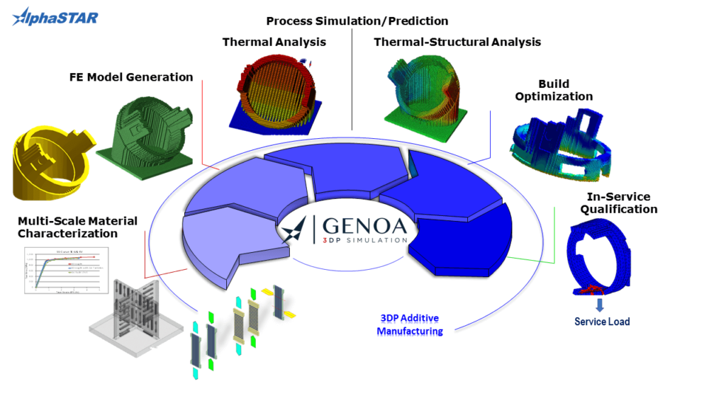
Using this approach, you can create such models in other programs. nine0003
Door handle model here: http://3dtoday.ru/3d-models/for-home/kitchen/dvernaya_ruchka_pod_derevo/
Bye everyone! Take care of yourself and your loved ones.
#Contest_Ultimaker
3D printing with epoxy composites can mimic the properties of cork material
Archive
-curable polymers, but now scientists from the Harvard School of Engineering and Applied Sciences have teamed up with the Wyss Institute of Bioengineering to create an epoxy-based thermosetting polymer for 3D printing. These epoxy composites allow printing with materials that are used as structural components for lightweight structures. These new 3D materials consist of epoxy resins combined with nanoclay particles to increase viscosity and a dimethyl methylphosphonate compound. To this mixture are added two fillers, silicon carbine and carbon fibers. nine0003
The orientation of these fillers in the media determines the versatility and strength of the printed material. This blend is a composite whose strength and stiffness can be adjusted and is approximately 200% stronger than the best printed resin composites currently available. The description of the study was published in the article "3D printing of lightweight cellular composites" in an issue of the journal Advanced Materials, co-authored by Brett Compton and Jennifer Lewis. nine0003
Epoxy 3D printing of cellular structures. In the right image, you can see how the fibers align as they pass through the extruder nozzle.
Lorna Gibson, Professor of Materials Science and Engineering at the Massachusetts Institute of Technology explained the significance of this research:
“This paper demonstrates for the first time 3D printing of cellular structures with fiber-reinforced cell walls. Of particular importance is that the fibers can be aligned by controlling the ratio of parameters such as fiber length to fiber diameter and nozzle diameter. This marks an important step forward in the development of building materials that mimic wood.” nine0103
Why is it so important to imitate wood in this way? After all, we have wood, right?
The main potential for using this material is to create structural honeycombs that will serve as core inside wind turbine blades. Currently, these blades are filled from the inside with compressed building materials, one of which is cork wood. Despite the fact that balsa (cork tree) is considered a fast-growing tree and belongs to a rapidly renewable resource, its wood has small variations, due to which it can be quite difficult to choose exactly the one that fully meets the requirements established for such products. In addition, balsa wood is a relatively expensive material, and as the length of the blades used in these wind turbines increases, some of which are already about 250 feet long today, the cost and the need for precision also increase. Using this material and 3D printing technology, researchers have been able to create cellular composite materials that are superior to balsa wood in terms of properties.
nine0003
But this material could be used for more than just wind turbines, as fuel efficiency requirements in the automotive industry are becoming ever more stringent, a strong and lightweight material like this could be exactly what will help designers build ever better cars, conforming to these standards.
Compton sees the future use of this epoxy composite as follows:
“Because we have been able to achieve additional levels of control in filler alignment and learn how to better integrate these directional fibers into component design, we can further optimize component design to improve material performance. Eventually, we will be able to use 3D printing technology to change the degree of fiber alignment and local composition on the fly.” nine0103Various cellular structures 3D printed from epoxy carbon fiber composites and conductive properties.
What other applications could this material be used for? Share your opinion in the comments to this article.

Learn more


