Finish 3d prints
Ultimate Guide to Finishing 3D Printed Parts
Time to read: 13 min
The purpose of this article is to detail the different finishing methods for FDM and PolyJet 3D printed parts and the techniques/tips that can elevate the look and feel of your prototypes.
A simple Apple Watch stand design will be utilized as a case study. This stand is a model with pockets and internal and external features that needs to be surface finished to a standard that complements the shiny exterior of an Apple Watch put on it.
Here’s a quick overview of the main points this article covers:
- PLA: If you’re working with a tight budget then PLA is going to be your best material choice; the results aren’t as polished but the price is cheapest.
- ABS: If your budget is moderate then go with ABS. It’s not as cheap as PLA but still at a low price point and the material is more reliable than PLA.
- VeroBlack or VeroWhite: For the highest quality parts go with VeroBlack/VeroWhite.
This will give you the best dimensional accuracy and best overall polished look.
The 3d printing post-processing needed for the watch stand parts involves a combination of repairing and preparing the print for post-processing, sanding, and painting.
The finished sample 3D printed parts with all three materials should be smooth, matte black surfaces. Inherent to the 3D printing process, with every print are unique challenges and considerations to arrive at the best finish possible. Although there are ways to mitigate the challenges, experience in 3D printing goes a long way.
The print settings process for each material is detailed separately and a summation of the results may be found in the conclusion of this article.
ABS (Printed on a Dimension Elite)
The Dimension Elite prints are smooth, clean, and ready to sand out of the NaOH bath.
There are, however, clear stepping lines between the printed layers. If we don’t remove these stepping lines, they’ll show up in the final paint coat which will ruin our smooth finish. Thankfully, removing these will be easy thanks to ABS’s high melting point and easy sandability.
Materials Needed
The materials we’ll be using:
- Sandpaper (grits 100 to 600)
- Medium, fine, and extra-fine sanding sponges
- XTC-3D brush-on coating (As an alternative, Bondo putty is a common solution to fill holes in parts. We chose XTC-3D for its viscosity, sandability, and ability to penetrate small perforations, which makes it desirable over Bondo putty)
- Razor blade
- Foam brush, mixing cups and popsicle sticks
- Sandable Krylon Primer
- Montana Acrylic Primer in Shock Black
- Matte Acrylic Varnish
Sanding
Sanding the ABS print is simple and straightforward. First start with 100 – 200 grit sandpaper to remove stepping lines and then gradually increase up to 600 grit to achieve a smooth finish without sanding lines.
Pro Tip: Sand in small circular movements evenly across the surface of the part. Avoid sanding in one direction only, especially in the direction of the stepping lines to prevent striations or “trenches” in the print.
Beware that ABS is very easy to sand, so be careful not to overdo it. Removing as little as .010” can be enough to completely remove any stepping layers and oversanding can compromise critical dimensions.
After sanding the parts, some holes are revealed on our part left by an incomplete layer around the letters DIM. These holes can perforate through the finished paint coat to create ugly sinkholes, so we need to find a solution.
As you can see in the Catalyst tray to the right, there are large holes between the DIM and the edge of the part. Moving the DIM up in our Solidworks model would solve this, but for now we’ll have to find a way to fill these holes with a sandable filler.
Repairing the Incomplete LayerWe’re going to use a thin, sandable epoxy called XTC-3D to fill the tiny holes and crevices in our print. XTC-3D is cheap (a 24 oz bottle costs about $25), quick, thin, and effective. Note that a small amount goes a long way (within the 10 minute pot life).
Pro Tip: Be sure to maintain a weight ratio of 100 Part A to 42 Part B. Mix thoroughly for one minute and coat your part within the 10 minute pot life. For more details, check Smooth-On’s technical bulletin here, and a great instructional example here.
Before applying the XTC-3D, wash the part with soap and dry with compressed air to ensure your part is thoroughly clean and free of any oils or sanding dust. Also make sure to wear gloves so as not to get any hand oils or sweat on your part.
Fill in holes or gaps in your print with a very thin (1/64”) coat; a thin layer of XTC-3D will level itself out. We used a razor blade to scrape excess XTC-3D into the unwanted holes and gaps, making sure to avoid any areas we didn’t want filled (like the letters DIM).
Allow the XTC-3D sufficient time to become tack-free dry (approximately 2 hours). Now we’re ready to continue sanding away at the excess XTC-3D layer with 300 to 600 grit to reveal the repaired surface.
Then, after another thorough wash, we’re ready to begin preparing our repaired surfaces for painting.
Priming and Painting
Painting 3D printed parts is a vast world of acrylics, enamels, sprays, and airbrushes.
In this example, we’ll be using Montana spray can paints to follow a relatively straight forward process: prime, dry, paint, dry, varnish, dry.
Standard spray painting principles apply:
- First make sure your surface is oil-free, dust-free and hole-free
- Shake your cans for at least two minutes prior to painting
- Ensure your cap is clean to prevent drips
- Be aware of how the paint is accumulating on the part and look for any pooling or dripping
- Paint in many light coats rather than fewer heavy coats; this is especially important for 3D printed parts with internal and obscured geometries
- Paint in controlled, well-ventilated and well-lit areas
The Dimension prints started with very obvious stepping between layers.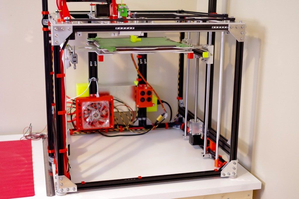 If you’ve sanded properly up until now to create as smooth a surface as possible, these layers shouldn’t show up in your final paint finish.
The finished ABS part is matte black and smooth to the touch with very little evidence of layering in most surfaces. A few important results to note here:
- Sharp internal pockets are tough to sand. After about 30 minutes of sanding, we still had a hard time removing all the layering and the stepping shows up even after priming, painting, and varnishing the print.
- Because we had to remove more surfaces from the sanding, there is some sacrifice in regards to the final geometry of the part.
- Filling the incomplete layer with a thin coat of XTC-3D worked very well; those holes are invisible in the final paint layer.
VeroBlack (Printed on an Objet30)
Thanks to .0011” resolution, the Objet30 prints have some stepping between layers, but nowhere near as obvious as in our FDM prints.
The Objet30 prints come out of the printer with a thick layer of support structure material so before we can begin finishing our VeroBlack part, we’ll need to remove this support structure and the residue it leaves behind.
VeroBlack 3D Printed Part Materials NeededThe materials needed for post-3D printing finishing:
- Sandpaper (grits 100 to 600)
- Medium, fine, and Extra fine Sanding Sponges
- Sandable Krylon Primer
- Montana Acrylic Primer in Shock Black
- Matte Acrylic Varnish
Start with 100 grit sandpaper to wet sand the residue and gradually move to wet sand with 300 grit sandpaper; the residue will fall off in small soft white chunks. This is the hardest part of the VeroBlack finishing process and it took us about 30 to 40 minutes to remove all the residual layer.
After removing the residual layer by wet sanding utilizing 300 grit sandpaper, the surface of the part will begin to feel smooth. If you rub the part with your fingernail, you’ll feel it’s harder and more plastic-like beneath the gummy residual coat. Continue wet sanding through to 600 fine grit sandpaper until the part is fully smooth.
Pro Tip: Water breaks up the residue, so wet sanding is a highly effective method to get a smooth, residue-free, paintable, and homogenous surface.
Thoroughly clean your part with soap and water before you move on to the next step to remove any additional residue. Again, we recommend using compressed air to dry the part and clear any accumulated dust.
Beware that VeroBlack is like ABS: very easy to sand, so be careful not to overdo it. Once you break through the residual layer, the actual VeroBlack will sand very easily. Removing as little as .005” can be enough to completely remove any stepping layers. Be careful as oversanding can compromise critical dimensions.
VeroBlack 3D Printed Part Priming and PaintingNext, we’re going to paint the VeroBlack part just as we did the ABS part: using Montana spray can paint with the following process: prime, dry, paint, dry, varnish, dry.
Standard spray-painting principles apply:
- First make sure you have a good surface quality which is oil-free, dust-free and hole-free
- Shake each paint can for at least two minutes prior to painting
- Ensure your cap is clean to prevent drips
- Be aware of how the paint is accumulating on the part and look for any pooling or dripping
- Paint in many light coats rather than fewer heavy coats; this is especially important for 3D printed parts with internal and obscured geometries
- Only paint in controlled, well-ventilated, and well-lit areas
The finished VeroBlack part is matte black and smooth to the touch. A couple points to note here:
- Some of the internal corners were not sanded enough to remove the residue, so you can see how the paint powdered up in these areas.
 This will likely result in peeling paint over time.
 - Although very little stepping is visible on the part, you can see slight evidence of it here. This part could have probably used 30 more minutes of thorough sanding.
Now for the dreaded PLA, a notoriously difficult material to finish. But with some tricks and patience, it too can join ABS and VeroBlack in the ranks of matte black glory!
This Replicator print came off the plate with severe striations: see the parallel grooves in the layers of the part above. This could be a result of machine quality, but for now we’ll just have to find a way to maneuver these striations to a smooth part.
Sanding PLA is difficult, in part because of how soft and gummy it becomes if you try to sand too aggressively or quickly, so we’ll explore options on how to smooth 3d prints with minimal effort and abrasion.
PLA 3D Printed Part SandingIf you choose to sand the PLA directly, the process is straightforward. Note: PLA acetone smoothing is not advisable. PLA smoothing is not as forgiving as ABS when it comes to sanding and abrasion, so you will likely spend more time removing the stepping between layers, especially with the severe striations in a print like ours.
Begin with a low (100 – 200) grit sandpaper, sanding away at the bumpy striations and any raft or support material (aluminum foil) left behind. Particularly in the case of MakerBot support, it’s easiest to remove them with a flush cutter or pair of pliers and brush them with a rotary multi-tool first before sanding away at them.
Depending on the size and geometry of your part, you’ll likely be stuck in the 100 – 300 grit sandpaper range for a while to smooth out striations and pesky support structure remnants.
Once layering and striations are less prevalent, move through finer grits (400 – 600) sandpaper to achieve a shiny surface ready for priming and painting.
Pro Tip: Patience is key when sanding PLA. Turn on a movie or your favorite show, but don’t zone out! Sand in small circles evenly across the surface of the part. If you’re using a sanding multi tool on PLA, be careful not to overheat/melt your 3D printed part.
An alternative method to sanding PLA prints directly is smoothing the PLA print with the XTC-3D first and then sand on top of the coating.
PLA 3D Printed Part FinishingWe’re going to use XTC-3D to create a smooth, sandable, paintable layer of epoxy clear coat glossy finish around our PLA print.
Before applying XTC-3D, ensure that your part is thoroughly clean, free of any oils and sanding dust (sensing a pattern yet?). Wash the part with soap and dry with compressed air to clear any dust. Again make sure to wear gloves to protect both your part and your hands.
Brush on the XTC-3D in a thin (1/64”) coat; as long as the coat is thin enough, it will level itself out. Between coats, leave 1.5 hours for the XTC-3D to dry.
It may be difficult to coat an entire part at once, so don’t be afraid to do it in sections, making sure to keep overlapping to a minimum between sections. Wait 90 minutes between first and second coats and after you’ve finished wait 2 hours to allow the shiny surface to become tack-free.
With striations as severe as ours, it will take multiple coats to get a smooth uniform surface, so patience is key. Remember that multiple thin glossy finish coats will level better than thick coats.
Pro Tip: Internal pockets are susceptible to pooling so be careful to suck up or remove any pooling that occurs before the XTC-3D begins to dry (that’s what we’re doing in the left picture above).
Beware that XTC-3D may compromise critical dimensions, but applying thin glossy finish coats will allow you to minimize the additional material.
After the XTC-3D layer has hardened (two hours after application of the last coat) it should be ready for sanding. Follow basic sanding guidelines, starting with 300 grit sandpaper (thanks to the smoothness of the XTC-3D) and sanding in small circular movements to even the surface. Any wavy patterns may require a coarser grit sandpaper to remove.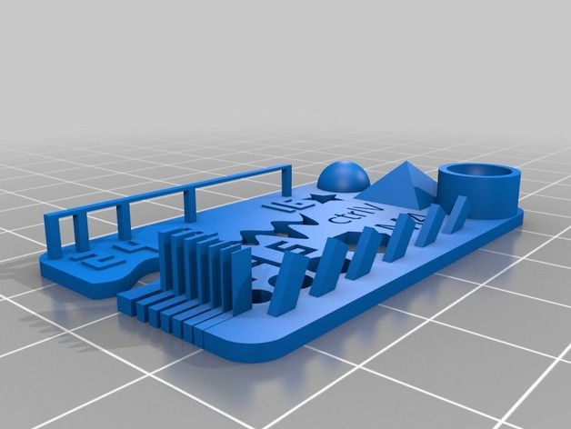
The sandpaper will scratch up the XTC-3D coat; focus on getting a level surface, moving through to 600 grit sandpaper.
After you’ve finished sanding 3D prints, make sure to thoroughly clean your part with soap and water and then dry using compressed air before moving on to the next step.
PLA 3D Printed Part Priming and PaintingPainting PLA parts follows the same process as the ABS and VeroBlack parts: prime, dry, paint, dry, varnish, dry.
Standard spray painting principles apply:
- Make sure your surface is oil-free, dust-free and hole-free
- Shake your cans for at least two minutes prior to painting
- Ensure your cap is clean to prevent drips
- Be aware of how the paint is accumulating on the part and look for any pooling or dripping
- Paint in many light coats rather than fewer heavy coats; this is especially important for 3D printed parts with internal and obscured geometries
- Paint in controlled, well-ventilated and well-lit areas
The XTC-3D coated PLA part is matte, black, and has a smooth surface to the touch with a few problems:
- Although the XTC-3D has worked well to smooth the part and make sanding quicker and easier, it has left pooling in the internal pocket that has shown through the paint finish.
- Striations are still visible on the part. 30 more minutes of sanding 3D prints could have prevented these from showing through the final paint finish.
After finishing all three parts to a smooth, matte black finish, let’s take a look at the differences in process, time, materials and finish.
Differences in ProcessABS (Dimension Elite)- Sand from 100 to 600 grit
- Repair holes with XTC-3D (may not apply to your part)
- Sand away XTC-3D with 300 to 600 grit
- Prime, Paint, Varnish
- Sand from 100 to 600 grit
- Prime, Paint, Varnish
- Coat in 1 to 3 layers of XTC-3D (depending on how bad the striations on your print are)
- Sand away XTC-3D with 100 to 600 grit
- Prime, Paint, Varnish
The part that took the longest to finish was PLA due to the XTC-3D coating time. Even without XTC-3D, however, PLA typically takes longer to sand than ABS or VeroBlack.
In our example, the VeroBlack was ultimately faster to finish since we repaired our ABS print with XTC-3D and stepping between layers was not as significant in the VeroBlack print.
All things considered, VeroBlack was the quickest to get to a smooth, matte black finish.
Pro Tip: If you’re in a rush to get from printer to photoshoot, pick the Dimension Elite or Objet30. Especially in models with overhangs and significant amounts of support material, the Dimension Elite and Objet30 both have support material that is quickly removable via dissolution, whereas the PLA support on a Replicator can significantly increase the time required to get to a smooth surface part.
Differences in Cost and MaterialsIt’s important to consider the amount of time it will take to finish your model as well as the overall look and dimension when considering the price.
PLA is the cheapest out of the three, at $20 per part, followed by ABS at $55, and VeroBlack at $110. In our opinion, VeroBlack is the best bang for your buck since it’s the shortest to surface finish and will give you the most accurate model.
At first glance, all three models may look very similar, but there are a few key differences in the final finish.
Both the ABS and the PLA finished prints have evidence of stepping between layers that is visible in the final paint coat. The VeroBlack print requires much less effort to remove these steps, which ultimately are not as obvious in the final paint coat.
Although the ABS and the VeroBlack finished prints have very similar surface finishes, more material (approximately .020”) was lost in the sanding process for the ABS to remove stepping between layers. In contrast, the VeroBlack print required less sanding, so the final object dimensions are closer to the original design intent.
Individual Summary of Each PartVeroBlack: High layer resolution (. 0011”) means little sanding is required to get a smooth, paintable part. Critical dimensions don’t need to be compromised to get a smooth surface quality part and no repairs are needed for fine detailed features.
ABS: Parts are easy to sand, but small fine detailed features may require repairing and careful sanding to remove stepping between layers. Once this stepping is removed, painting is straightforward.
PLA: The cheapest option, but also has the potential to be the most difficult to finish, depending on support structures and quality of the print. May require significant sanding and repairing via XTC-3D or Bondo filler.
Browse our website to learn more about our capabilities, such as 3D Printing and CNC Machining.
Quick Facts:
- Finishing a 3D printed part often involves a combination of the following processes: smoother application, sanding, polishing, cleaning and painting. The process is unique to the material type.
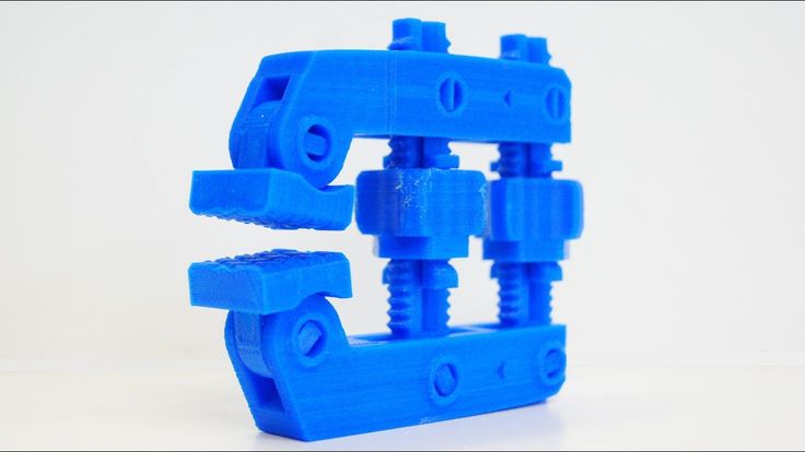
- A smooth finish with 3D printing is achievable but, post-processing will greatly improve the smoothness of parts.
- Epoxy resins are an excellent choice for sealing PLA printed parts.
- Acetone smoothing is not recommended for PLA prints.
- In general, IPA or rubbing alcohol will not dissolve PLA but there are some varieties that may be IPA soluble. Consult your filament material datasheet or technical datasheet for more information.
- PLA may be smoothed without sanding by dipping it or spraying it with a coating.
- ABS is tougher and lighter than PLA which is stronger and stiffer. Both have their ideal applications, but PLA is typically considered a hobby material whereas ABS is ideal for prototyping.
How To: Smooth and Finish Your PLA Prints - Part 1
Making your 3D prints look fresh off the assembly line isn't as hard as you think. Follow these simple techniques to finish your 3D prints and make them shine.
Updated on November 14, 2022
by
Alec Richter
PLA (Polylactic Acid) filament is one of the two most commonly used desktop 3D printing materials (with the other being ABS filament). It is the ‘default’ recommended material for many desktop 3D printers, and with good reason - PLA is useful in a broad range of printing applications and can be produced in a variety of colors. It has the virtue of being both an odorless and low-warp material, and does not require a heated bed. PLA plastic is also one of the more eco-friendly 3D printer materials available; it is made from renewable resources (corn-starch) and requires less energy to process compared to traditional (petroleum-based) plastics. Cool, but what do you do to finish a PLA print to make it truly good?
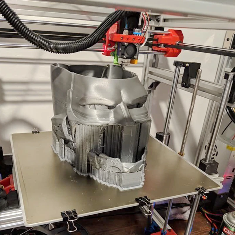
Yes, this Halo helmet is 3D printed!
There are several techniques to remove or diminish the striations or layer lines of a 3D print.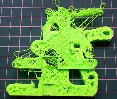 Some of the different processes that can be applied to PLA can be applied to ABS, but not vice versa. Generally, for PLA filament, the methods you can use involve the continual adding and subtracting of different materials back and forth until it is as smooth as you want it.
What do I mean by finishing?
Think of your 3D prints as the Great Pyramids of Giza. They used to be totally smooth down the side, but age has revealed the layered and rough base built underneath. To make the pyramids smooth, Ancient Egyptians added limestone over the top, since it was a much softer material than the base stone. If they had the technology, they also could have cut away the jagged levels to make smooth, flat faces. This is what finishing consists of; a fine balance between adding and subtracting material to achieve the desired surface finish. The key is to remove enough material to hide some striations (layer lines) and adding just as much to fill in the gaps.
To help showcase the benefits and problems that can arise with each technique, I’ve designed a “Finishing Torture Test.” This simple model has sharp corners on the outside of the cube and the inside of the hole, along chamfers, and the edges of the pyramid. It also has round faces, fillets, and a cylinder. I chose to include all these in the model as they are different examples of some common features you might find in the various models you can print, and to show how some of the features can be lost or diminished.
If you'd like to put your finishing skills to the test, you can download this model from our Thingiverse or from the Design Store
Finishing Torture Test
I started by printing out the model in MatterHackers Silver PRO Series PLA. This will serve as the control print. I then repeated the print eight more times. The eight prints will be used to demonstrate four different techniques, each with two different finishes.
The control print.
As this in an introduction to finishing PLA, this list is non-exhaustive of the techniques you can learn to clean up your 3D prints. More tools can be used, small tips can be learned, and starting with a good model are all techniques you can use to produce finished prints, but the ones I will be going over are:
- Painting alone
- Sanding and painting
- Sanding, filler primer, and painting
- Sanding, filler primer, spot putty, and painting
Note:
If I were doing this with the intent to mold these or use these as a finished product, I would have gone through each step half a dozen times over, moving from low to high grits, priming, more sanding, priming, sanding, spot putty, sanding again, etc. Since the purpose of this article is to show the difference each material introduces to the finish of your part, only one pass of sanding and finishing is done to each part.
Painting
Painting is the least involved of any of the techniques; all you need is a rattle can and some open air and you can paint your 3D print.
Materials:
- Spray Paint
Some recommendations to follow when spray painting:
- Don't spray right up against your print: if you spray too close to your print, you risk getting noticeable drips in the paint job.
- Spray in a back and forth motion, overlapping each pass.
- Multiple coats will fill in the striations better than one coat alone, but keep each coat light.
Total Time: 1 minute (not including drying times)
Here you can see that there are still a lot of striations visible even after the paint, but it's less than if it was unpainted.
Left: Control, Right: Spray Paint
Sanding and Painting
Sanding is going to be the most common finishing technique, with any 3D printing filament. It’s easy, and it’s cheap, but that doesn’t make it any less tedious. The lower the grit, the coarser the sandpaper is, and the quicker it’ll remove material. I use 3M Pro Grade Precision because its backing is a little sturdier so it doesn't rip as easily and it lasts a while longer because the grit doesn't gum up as quickly as normal sandpaper.
Materials:
- Sandpaper
- 120 grit
- 200 grit
- 400 grit
- Water
- Paper towels
- Spray Paint
Start with the 120 grit and focus on the sides of the print. 120 grit will tear away material pretty quickly, so avoid sanding corners, edges, and any fine details.
Sanded using 120 grit
Continue to progress through the grits as you need to remove less and less of your print. Once you’ve finished with 200, start using water as you sand.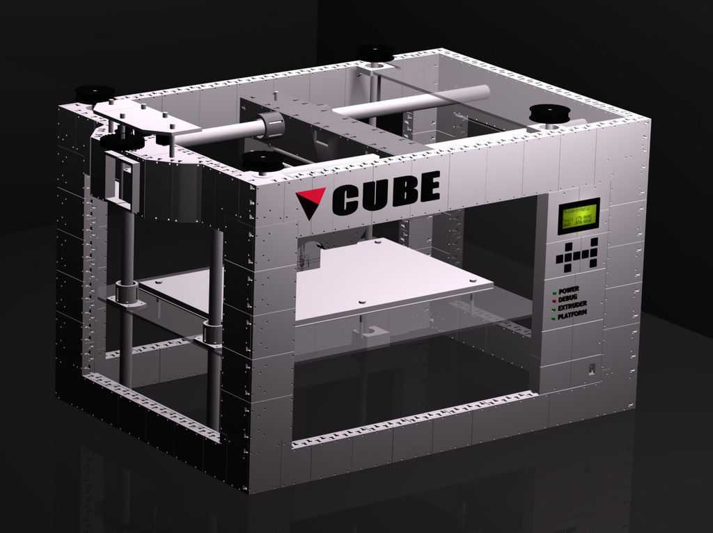 400 grit and above is going to remove very little material, any major blemishes or layer lines in the model will be mostly unaffected at this point, and will more or less be polishing what you have.
Dip your piece of 400 grit sandpaper into some water and continue sanding your print. The water helps keep the paper from clogging and gets a much finer finish than dry sanding with the same grit. As you sand, run your fingers over the print to get a feel for how smooth it is. When you think it’s pretty smooth, you're ready for paint.
Here is what the 3D print looks like after two matte gray coats of paint or two gloss gray coats. Keep in mind these are cheap Rustoleum rattle cans, but these prints do look better after having been sanded and painted.
8 minutes using 120 grit
6 minutes using 220 grit
5 minutes using 400 grit
1 minute spray painting
Total time: 20 minutes (not including drying time).
Left: sanded, matte paint; Right: sanded, gloss paint
Filler Primer
Once you’ve given it a quick sanding, spray on some filler primer to coat the entire 3D print. Keep alternating through sanding with 120 and spraying filler primer until things like the dome on top are filled in enough to make one smooth surface, rather than the clear layer lines on top. Once it’s filled in enough, repeat the steps listed in Sanding and Painting.
Materials:
- Filler Primer
- 120 grit
- 200 grit
- 400 grit
- Water
- Paper towels
- Spray Paint
Start by sanding with 120 grit sandpaper to bring down some of the surface texture. Before adding more material on top, it’s always better to remove some material first.
8 minutes using 120 grit
1 minute spraying the filler primer
7 minutes using 120 grit
10 minutes using 220 and 440 grit
Total time: 26 minutes (not including drying time).
Left: sanded, filler primer, sanded, matte paint; Right: sanded, filler primer, sanded, gloss paint.
Spot Putty
Spot putty is a great material and like any great material, slightly toxic. Gloves are a must as spot putty is basically dye, resin, and talcum powder, and a mask is based on personal preference but always encouraged. The label does list the vapor as harmful, but it's in such small quantities I usually ignore it, although it has given me headaches on several occasions.
Materials:
- Filler Primer
- Bondo Glazing and Spot Putty
- 120 grit
- 200 grit
- 400 grit
- Water
- Paper towels
- Spray Paint
- Gloves
- PPE
This is basically the same as the last process, except you will be using the spot putty to fill in any low spots to fill in some of the major layer lines, or rebuild minor blemishes like the top of round surface.
First, you're going to want to follow the steps I've given for filler primer, up to the point of switching to 220 grit. Instead of changing grits, you're going to do the following steps instead.
To apply spot putty, either use your gloved finger, a small paddle, scrapers, the side of a plastic scrap, a popsicle stick, it doesn't really matter. My personal preference is to use my finger for most and a small spreader for the tight spaces. Using a pea sized amount of putty, I smear it across the surfaces of the print and try to spread it thick enough to fill gaps but thin enough to not lose the details I'm trying to preserve. Either way, it's really easy to sand off so don't worry about overdoing it.
Once you've covered the entire 3D print with spot putty, wait 15 minutes or so until it has cured. After it has cured and is no longer gummy, start sanding again at 120 very briefly. Like I said, it's mostly talcum powder so it's going to be really easy to sand, you're basically wiping it off. When your 3D print looks like you initially did only a light coating, with pink spots of putty all over, you're ready to bump it up to 220 grit. At that point, follow the previously listed directions for sanding.
8 minutes with 120 grit
1 minute spraying filler primer
5 minutes applying spot putty
3 minutes with 120 grit
10 minutes with 220 and 400 grit
1 minute spray painting
Total time: 29 minutes (not including drying time).
Left: sanded, filler primer, sanded, spot putty, sanded, matte paint; Right: sanded, filler primer, sanded, spot putty, sanded, gloss paint.
Comparisons and Final Thoughts
From left to right: Control, Painted Matte, Painted Gloss, Sanded with Matte, Sanded with Gloss, Filler with Matte, Filler with Gloss, Spot Putty with Matte, Spot Putty with Gloss
Each technique took more time than the last, but you also get much better results - after all, it is a craft. Keep in mind that only one coat of filler primer and spot putty was used during the process (for the sake of time), but you can use as many coats as you'd like to eliminate layering. As you can see in the picture above, the results are still pretty stellar for only half an hour of work. For reference, the picture below is the 3D printed Torture Test before they were spray painted.
From left to right: control, sanded, sanded with filler primer, sanded with spot putty.
For part two in this series, read the sequel article, How To: Smooth and Finish Your PLA Prints - Part 2
Article Tags
- 3D Printing
- Firmware
- 3D Design
- MatterControl
- Press Releases
- Small Business
- Automotive
- E3D
- Jewelry Making
- Engineering
- Entertainment Industry
- MatterControl Touch
- ESD Materials
- NylonX
- BCN3D
- Open Source
- Crafty Pen
- Digital Fabrication Anatomy
- How To
- Hardware and Upgrades
- Tips and Tricks
- Weekend Builds
- Top Ten
- Education
- Tech Breakdown
- Women in 3D Printing
- Project Ideas
- Advanced Materials
- Reference
- Pulse Dual Extrusion
- Product Spotlight
- Aerospace
- Jobs
- Military & Government
- Multi-Tool Machines
- Getting Started
- Healthcare
- How To Succeed With Any 3D Printing Material
- Creality3D
- Architecture
- 3D Printer Reviews
- Hacker of the Month
Related Products
View all related products13 notes about 3D printing, after 3 years of owning a 3D printer / Habr
This article will be, first of all, of interest both to those who have directly dealt with 3D printing, that is, who owns a 3D printer, but also to those who are just about to join the ranks of 3D printers and are thinking about buying their own printer.
In the framework of this article, I want to present my observations, as a direct owner of a 3D printer, for more than 3 years.
Despite the fact that 3D printers have been known for a long time and, in my memory, have become widely used, judging by the information on various resources, starting around 2010 (I may be wrong, these are my subjective observations), for a long time I ignored this area, it’s hard to say why…
Probably thought it was some kind of "childish pampering", another hype topic for which there is simply not enough time...
The turning point happened when one of the wheels on my travel suitcase wore out. You know, a big plastic suitcase, with four spinning wheels on the bottom. Unfortunately, it is a “rather disposable thing”, due to the lack of bearings on the wheels, which is why the wear of the friction point of the axle and wheel allows the suitcase to last no more than one or two seasons. nine0003
And it’s like “lightning flashed in the middle of the day: 3D printer!” It is with his help that I can fix this problem! Looking ahead, I’ll say that I didn’t succeed in fixing the suitcase in this way, so I had to use a different approach . ..
..
As a result, I “upped” it - installing wheels from unnecessary roller skates. Thanks to this “up”, the suitcase has become a real all-terrain vehicle and, even being very loaded, it rides easily - pushed forward even with “one finger”. And even in the snow, 5-6 cm thick. A tank, not a suitcase turned out! By the way - I took spinning wheeled "units" in Leroy. Then he took off and threw out his native plastic wheels from there, inserting from roller skates:
But this thought itself became a kind of trigger that allowed me to finally join the world of printers and buy my first 3D printer.
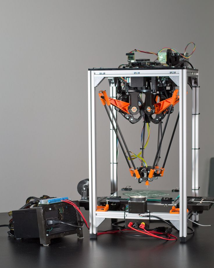
Like many, before buying it, I studied various forums and sites for a long time, delving into all the subtleties. And for some reason, I immediately liked the type of printer called the delta printer. Probably because during operation it looks like some kind of "alien device".
If at your leisure you like to sit “looking into the carpet”, then with the advent of such a printer you will have a much more interesting activity, even hypnotizing, one might say :-))
And this, in fact, is my delta (if anyone is interested), which went through, let's say, the "ultimate up": all the electronics are placed upstairs, on a self-made welded frame, covered with polyethylene and a magnetic door is made. The coil with a bar is installed at the top, on the frame. The axis on which the coil is put on is machined on a lathe from aluminum and a bearing from the VAZ timing is inserted into it. As a result, the coil - "rotates even from the passage of a fly nearby":
Well, yes, I won’t argue for a long time, let’s start reviewing the main facts that I have accumulated as a result of owning this car ... The facts are purely subjective and may differ from your vision. In any case, I will be glad to comments, clarifications, etc. nine0003
▍ NOTE 1. Delta is good, but...
Here I should give a number of my observations regarding the delta printer:
- It contains a completely finished frame of the future box, which makes it easy to form a heat chamber. I understand that many printers are made in the form factor of a “certain box” (but this point cannot be ignored), which greatly facilitates the process of wrapping this box with heat-insulating material.
 In my case, as such a material, I used a plastic film. nine0032
 - Already thanks to its design, delta allows you to work at much higher speeds than XY printers. By the way, it is on the delta principle that many modern high-speed industrial robots are built to sort various parts directly on the conveyor belt:
However, this plus does not allow to fully realize the occurrence of parasitic vibrations, even despite their suppressors:
Thus, accurate printing is possible, only at speeds (at least that was the case for me), no more than 60 mm per second. A complex procedure for aligning the movement of the head parallel to the table, which is why, for many, the so-called "lens" appears. People struggle with it with varying degrees of success, but I have not encountered this on my printer and for me, therefore, the “lens” has never been a problem. At the same point, it is worth noting the calibration of the table, which was initially absent on the first deltas, and I had to use an external third-party solution from one American do-it-yourselfer called EZBED.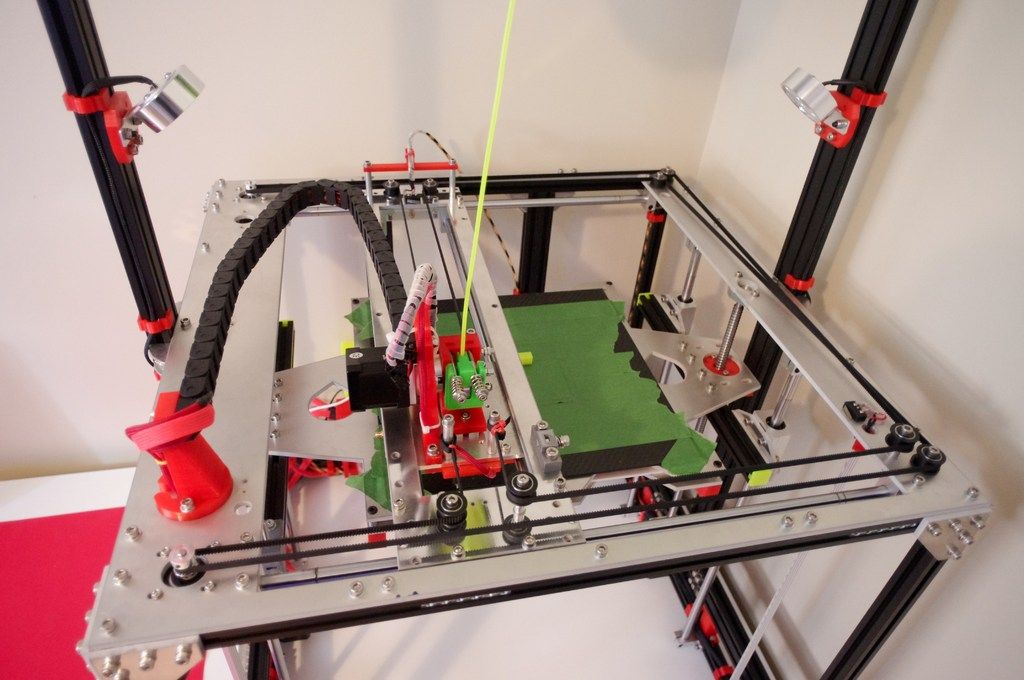 This solution was a hardware-software complex that allows you to quickly and easily calibrate the printing table, that is, to let the printer understand its geometry. Modern printers do not have this issue as they come with a built-in calibration solution. It is worth noting that I solved this problem by attaching a limit switch to the print head, and using the Marlin-1.1.9 firmware.
▍ NOTE 2. "Size doesn't matter..." :-)
When I got the printer, I was impressed by the possibility of huge printouts, a la the handguards of some futuristic rifles, huge body parts, etc.
However, if you try to analyze the results of your many years of practice, it turns out that in most cases, rather small objects were printed that easily fit in the palm of your hand, a maximum of two palms. Despite such a seemingly small size, the printing of these details took a significant amount of time. Of course, this very much depends on which nozzle you print with. But, despite this, it is difficult to disagree with the fact that most of the printed parts will be quite utilitarian and small in size. nine0003
Therefore, to be honest, the need for a printer that allows you to print "Venus de Milo in life size" is not obvious.
Of course, you can object to me that “I’m going to buy a printer, I’ll get used to it a little and I’ll get started!!!”
One simple point must be taken into account here: there are no universal things. And in order to understand how much 3D printing in general and your printer, in particular, you will need to solve your problems, and how much it will be able to solve such problems, you just need to first try the 3D printing method personally and then a lot will become clear to you . nine0003
Therefore, for a beginner, I recommend taking a small printer that allows you to print extremely small items that fit in the palm of two. With such a device, you will definitely never lose, as it will always be needed. In addition, with its help you will be able to get used to the printing process and, if necessary, purchase a larger device, already clearly understanding its capabilities and ability to solve your set of tasks.
▍ NOTE 3. "What type of printer to get." nine0027
Based on the foregoing, I do not recommend taking a delta printer and this can be said right away.
Not because it is bad, in fact, it prints quite accurately, its main problem (in my opinion) is the inability to print rectangular flat, fairly large case components, as well as the inability to fully realize high-speed work, since the quality drops critically. Here it turns out to be a rather offensive situation - the printer can work quickly, but this cannot be done, since the quality will be “nothing”. nine0003
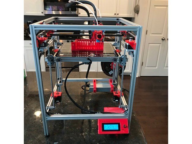
And then what kind to take? Depending on the budget and capabilities, I recommend taking any cube printer, for example, the same Core XY (the head moves, and the table goes down as the model “grows”, from top to bottom):
Image source: thingiverse. com
com
Such a printer allows you to easily print fairly large flat parts of cases, has good speed and accuracy. In addition, the presence of a rigid box-shaped frame allows it to be easily covered with polyethylene to create a sealed heat chamber. In addition, the very fact that the table does not move while working reduces the number of problems with model peeling. nine0003
However, the advantages of this printer will not be fully revealed if it has a direct extruder. On the one hand, it will allow printing with rubber-like materials, on the other -
large inertia and head weight. And these are parasitic vibrations, wear of the fur. parts, etc. (like everything in life, “we treat one thing and cripple another” :-))
At the initial stages, this may not be necessary, but in the future it may be necessary to print, for example, tires for your homemade car. And with this, the Bowden extruder has obvious problems. Although, in fairness, printing with such a rubber-like material is far from a daily need. However, whoever seeks will always find: over time, I found a way to “upgrade” my printer with a Bowden extruder to print with flexible materials. "Crutches" of course. But even so. nine0003
By the way, there are printers of a cheaper type, the so-called "drygostol", printing by moving the table and head:
They are inexpensive, moderately accurate, but they require a sufficiently high-quality gluing of the printed model to the table, because the table moves, and the model can come off when the table is jerked sharply. When printing large models, this can be a problem.
▍ NOTE 4. What to print with?
It's only a matter of taste and purpose. That is, if your printout will only stand on a shelf and should differ in some kind of aesthetic appearance, these are some requirements, if the printout is an engineering part that will be operated under conditions of increased mechanical load, these are different requirements. That is, in the first case, you can use any PLA, SBS plastics, and others with similar properties. nine0003
For engineering parts, for example, I only use ABS. It combines high hardness, strength and low price. Although I understand that now this last statement will cause a storm of comments in the style of “no! - there is even stronger, even better, the same PETG, etc. ":-)
Just here I wanted to say that thanks to the low price and the practical experiments that I conducted with ABS plastic, I realized that it is completely meets all my requirements. nine0003
However, the fact that ABS plastic releases carcinogenic substances when heated is quite annoying and forces you to take measures to prevent poisoning. For this, my printer prints completely closed and on an open balcony. After printing, the printer chamber opens, and it remains open in this form until it is completely ventilated and cools down.
▍ NOTE 5. "ABS is difficult to type on, it flakes, peels off the table, etc.
 .."
.." With a properly configured printer (in my case, at a print temperature of 205 degrees, a thermal chamber and a desktop temperature of 100 degrees), the use of auxiliary techniques, for example, among which, one can name the so-called ABS juice (which is ABS- plastic dissolved in acetone), you can create wear-resistant and durable things, without any hypothetical problems. nine0003
For example, my printer has been printing for many hours at temperatures well below freezing. And this happened more than once, not twice, not three! And the print quality was excellent:
12-hour ABS printing at -4 C
▍ NOTE 6. Acetone for post-processing and ABS juicing
At one time, I wrote a fairly detailed article on this topic and I will try to give the main excerpts from it. The essence of the issue here is as follows: due to the fact that different GOSTs are used for the production of acetone, acetone differs in quality. Despite the fact that it would seem that “acetone is also acetone in Africa,” nevertheless, one type of acetone can differ significantly from each other. For example, ordinary acetone, which can be bought at any hardware store, such as "1000 little things", "store near the house" and the like, is very low quality acetone, smells disgusting (although someone like it, maybe someone likes its pleasant building aroma and "aftertaste" :-))). nine0003
In contrast to it, there is a much higher quality acetone, which, however, is not found at all in any household stores, even large chain stores, such as Auchan or Leroy Merlin.
This type of acetone is found exclusively in shops that sell varnishes and paints for automotive work, i.e. these are highly specialized shops for car workshops:
Acetone, which can be purchased there, is of excellent quality, smells almost like alcohol, quickly disappears,
:-) - this is a joke, of course, don't even try it.
However, its main advantage, compared to household type acetone, is that it perfectly dissolves ABS plastic and does not allow it to precipitate. For me personally, it was a very surprising observation when the same ABS plastic was perfectly dissolved with acetone from an auto shop, and completely precipitated when I tried to use household acetone (I just ran out of good acetone, and I had to use "what is "). nine0003
Therefore, if you want your results to always be excellent, then here is the right acetone. It should be labeled "for professional use":
▍ NOTE 7. What about ABS juice?
"ABS juice" is what printers call a mixture of acetone and pieces of ABS plastic dissolved in it. This mixture is smeared on the surface of the desktop before printing and allowed to dry. Thanks to this spread, the model easily sticks to the desktop and does not peel off during the printing process. After printing is completed and the platen has cooled down, the model can be easily separated. nine0003
All that needs to be said here is that, after trying different approaches over time, I settled on using flexible metal spatulas, also called “Japanese-style spatulas”:
According to the results of many tests, this method of spreading turned out to be one of the most convenient options, such spatulas can be cleaned very quickly and easily after work. In other words, highly recommended!
▍ NOTE 8. "Yes, nothing sensible can be done on it, I indulged a little and decided to sell it - you can't use it for anything good anyway"
I absolutely disagree with the statement above, which is periodically heard from newcomers to 3D printing. You can even say more: at the moment I can’t even imagine how I used to live without a 3D printer! Since it is he who makes it possible for any do-it-yourselfer to significantly expand their capabilities and make piece products, almost of factory quality! Of course, for this, appropriate hands must be applied to the 3D printer, but that’s another question… and take on things that I would never have thought to take on before! nine0003
For example, among my homemade products, the following can be listed:
- Heated sole for boots, which is a hose integrated into the insole (and filled with household silicone from a household store), through which water flows, heated with a catalytic type hand warmer.
 Water is pumped using a small peristaltic pump. The engine with a metal gearbox, which is used in the creation of this pump, allows you to develop a force of 3 kg, which is even redundant for this homemade product. The engine is powered by Peltier elements mounted next to the catalytic heater. The project is currently in progress. nine0032
- Centrifugal water pump mounted on the shaft of an internal combustion engine that drives a high pressure wearable air compressor with a pressure of 500 bar. The pump pumps coolant through the casing of the high pressure pump, or rather its second stage. Despite the fact that the pump is 3D printed and runs at over 6000 rpm, nothing “fell apart, fell apart, didn’t break.” As you can see in the photo, the pump is installed instead of the “starter”, that is, the armstarter. The compressor scheme as a whole is as follows: 2 engines. Connected by clutch. One is heavy duty. The second is modified and turned into a high pressure compressor:
Yes, before assembling this, I also did not believe that this was possible. Moreover, even when I collected it, I did not believe my eyes :-))). However, it is a fact…
- I printed a number of Rank-Hilsch test tubes, the essence of which I have described in detail in this article.
- Printed mass of parts, more than 100 pieces, to create 10 web-controlled robots. There was also a detailed article about this here.
Well, and a bunch of all sorts of useful and not very crafts. As you can see from my crafts above, I have a special passion for creating some useful things, a utilitarian direction. That is, so that the printout is useful, and does not belong to the type “yyy breathe, Mikola, what am I doing here” :-), and then put it on the shelf and that's it. Although, engineers are also not alien to beauties, and this will be my next fact below. nine0003
▍ NOTE 9 Proper placement of the model when printing is half the battle
It would seem an obvious fact, but many underestimate it. Here I mean the following: by experience, I accidentally discovered that when printing various statues (in which I, completely unexpectedly for myself, discovered another passion of mine), it is advisable to place the statues at an angle to the printing table.
This allows the layers in the printout to run at an angle of approximately 45-50 degrees to the model. The result of this is that the printed model is almost completely invisible layers and the model looks like it has been post-processed, but at the same time retains a deep matte color, which, to my personal taste, is more like a marble than a glossy result of processing in an acetone bath : nine0003
An additional advantage of this method is that the layers going at an angle of 45-50 ° to the model give it additional strength. This is especially true for printing statues, which contain many thin elements that are easily chipped when the statue is accidentally dropped from a table or shelf (learned from bitter experience, this happened to me many times, and ruined some fairly decent prints).
That is, the layers going across the model, if the model has a large length in height, does not allow it to maintain sufficient strength. For better understanding, I tried to illustrate this point in the figures below:
▍ NOTE 10. Bleeding must be taken into account when printing, especially if the model is composed of separate parts and must be assembled by joining these parts to each other, entering into each other, etc.
I tried to illustrate this point in the figures below. The implication here is that if you're printing a composite model, you need to correct for the amount of bleed on the plastic (I'm not sure what it's called, but at least I tried to convey what I mean). If this is not taken into account, then the model will not fit. nine0003
For example, in my case this correction is 0.2 mm per diameter - if I want the model to fit more tightly; if I need a free joint, without excessive density, then 0.3 mm per diameter:
That is, suppose that the blue part has a size of 10x10mm. So it must be modeled in a CAD program as 9.8x9.8 mm (if we want it to sit tight) or 9.7x9.7 mm (to sit freely). Well, or expand the hole in the green part, and leave the blue one as it is. nine0005 This is often a problem when you download a prefabricated model from the Internet - but it is not going to, even if you crack! And because no amendments have been made…
For your particular case, the amendments may be different.
▍ NOTE 11. What if...
In fact, this note complements note number 8. Using a 3D printer allows you to create metal parts using a printed 3D model. For this, the casting method is used according to the lost wax or burnt model. In our case, we will deal mainly with metal casting on a burnt model. nine0003
Briefly, it looks like this: printing a 3D model (using PLA plastic) → pouring it with plaster → burning PLA plastic, simultaneously with burning the mold, in a conventional stove oven → pouring the resulting mold with molten metal (melted in a conventional microwave) .
Image source: 3dtopo.com
I told about a simple method of melting metals in a home microwave oven here.
There was even a good article about casting on Habré. nine0003
▍ NOTE 12. Durability?
Despite the fact that ABS plastic is called exposed to ultraviolet radiation and, accordingly, burns out, losing its strength in the sun, in my practice, even printouts that are constantly exposed to the sun have not lost their strength and color at all, continuing to be successfully used and Currently.
It should also be added here that printouts are constantly exposed not only to the rays of the sun, but also work continuously in damp conditions! nine0003
As such printouts, I can give an example of winglets for technical cranes, which I printed out, but, unfortunately, did not photograph this process; as well as fasteners on shoes that I use “both in the snow, and in the heat and in the pouring rain, and in general are always with me”:
▍ NOTE 13.
 And what about the thread?
 Periodically, there is a need to print parts containing a particular thread. Modeling such products requires a good understanding of what a thread is in general, as well as what corrections need to be made in your particular case, which I have already described above. nine0003
But since I've owned a metal lathe for a long time, I'm not at all happy with the 3D printed carving that looks like "something very carving-like".
I am satisfied with an exceptionally perfect carving. Therefore, I keep in stock a large set of various taps and dies, with which I cut all my threads in plastic printouts:
I posted a photo of dies and taps not to brag, but to make the reader understand that serious carving requires a serious approach (unfortunately). And considerable costs for all this thread-cutting iron ...
To create your own threads (both threaded channels and threaded pins), I recommend the following reference materials: for holes, for pins.
Well, that's where I want to end my story and note that he does not claim to be exceptionally accurate and exhaustive. Nevertheless, I tried to state a number of my observations. It will be interesting to read yours, in the comments!
3D Printing G-code Basics: List and Guide
3DPrintStory 3D printing process G-code Basics for 3D Printing: List and Guide
G-code is a programming language for numerical control (CNC). In other words, it is the language that the computer that controls the car speaks, and it transmits all the commands necessary for movement and other actions. nine0003
Although G-code is a standard language for various desktop and industrial equipment, it can be very familiar with a 3D printer. You may not have figured this out yet, and that's okay, since 3D slicers generate G-code "automatically".
However, if you want to get a deeper understanding of 3D printing, it's important to learn the basics of G-code. This knowledge will allow you to better diagnose and control 3D printing processes, as well as configure 3D printer firmware such as RepRap or Marlin. nine0003
In this article, we'll cover the basics of G-code, including how to read, understand, and write commands, even if you're new to programming!
What is a G-code?
For those unfamiliar with programming in general, you can think of G-code as successive lines of instructions, each telling the 3D printer to perform a specific task. These lines are called commands, and the printer executes them one after the other until it reaches the end of the code.
Although the term "G-code" is used to refer to a programming language in general, it is also one of two types of commands used in 3D printing: "basic" and "auxiliary" commands. nine0003
The main command lines are responsible for the types of movement in the 3D printer. Such commands are denoted by the letter "G". In addition to controlling the three positive axes performed by the printhead, they are also responsible for the extrusion of the filament.
On the other hand, different commands force the machine to perform non-geometric tasks. In 3D printing, such tasks include nozzle and bed heating commands, as well as fan control, and so on. Auxiliary commands are denoted by the letter "M". nine0003
G-code syntax
Each G-code command line has a specific syntax. Each line corresponds to only one command, which can lead to very long codes.
The first argument of any string is the command code itself. As you have seen, this can be a code like "G" or "M" followed by a number identifying the command. For example, "G0" corresponds to a linear movement command.
Next are the parameters that define the command more precisely. For example, for a G0 linear motion command, you can add an end position and a travel speed, also indicated in capital letters. Each command has its own set of options, which we will discuss below. nine0003
G-code comments
When you read the G-code of a command, you will see semicolons after letters and numbers that explain what the code does. Here is an example of a line with a comment to the code:
G1 X25 Y5; I'm commenting out the code!
Programmers often need to include plain language explanations so that other programmers can understand certain lines or sections of code. It can also happen that you forget why you wrote something in a certain way, making it hard for you to figure it out again. Code comments are used to solve this problem. Comments include everything (on the same line) after the semicolon and are completely ignored by the machine when executing G-code. As such, they are solely for the eyes of programmers. nine0003
Important 3D Printing Commands
Although there are literally hundreds of G-code commands, in the next few sections we'll cover the most basic and important ones. Once you get comfortable, you can learn other commands on your own.
G0 and G1: linear movement
The G0 and G1 commands execute linear movements. By convention, G0 is used for non-extrusion motions such as initial and idle motions, while G1 covers all linear motions with material extrusion. nine0003
However, both commands work the same way. The parameters for G0 or G1 include the end positions for all X, Y, and Z axes, the degree of extrusion performed during the move, and the speed determined by the feed rate in given units.
Example
G1 X90 Y50 Z0.5 F3000 E1 tells the 3D printer to move in a straight line (G1) to end coordinates X = 90mm, Y = 50mm, Z = 0.5mm at a feedrate (F) of 3000mm / min. and extrusion (E) 1 mm of material in the extruder.
Most linear moves are within the same layer, which means that the Z coordinate is usually not specified on the command line.
G90 and G91: absolute and relative positioning
The G90 and G91 commands tell the machine how to interpret the coordinates used for movement. G90 sets "absolute positioning", which is normally the default, while G91 sets "relative positioning".
Neither command requires any parameters, and setting one automatically overrides the other. Positioning works quite simply, so let's get straight to the point. nine0003
Example
Let's say we want to move the print head X = 30 in a line. In absolute positioning mode it would look like this:
G90; sets absolute positioning G0X30; moves to X = 30
This simple move will tell the printer to move the printhead so that it is positioned at X = 30. Now, to move the relative position, we need to know where the printhead is currently located. Suppose it's X = 10:
G90; sets relative positioning G0X20; moves +20mm in the X direction
G91 first tells the 3D printer to interpret the coordinates relative to the current position (X = 10). Knowing this, it is enough just to move 20 mm in the positive direction of the X axis, thus reaching X = 30, as we would like.
G28 and G29: automatic zeroing and table calibration
Homing is the process of moving up to physical limits for all axes of motion. The G28 command will accomplish this task by moving the print head until the limit switches on all axes are engaged. nine0003
Moving "to zero" is important not only to orient the device, but also to prevent the printhead from running out of bounds. The G28 command is usually executed before every start of 3D printing.
A specific axis can be individually homed by including X, Y or Z as parameters. Otherwise, only G28 will provide movement to zero in all axes.
Example
G28 X Y; only X and Y axes G28; to zero on all axes
Another command, G29, starts the automatic table calibration sequence. There are many different methods for leveling a table before 3D printing. Usually this operation is provided by the firmware and not by the end users. For this reason, we will not go into details regarding the methods and parameters of commands. Just be aware that G29 is usually sent after automatic homing (G28). As a result, automatic table calibration should be performed, which is determined by the firmware. nine0003
G29; execute automatic bed leveling sequence
M104, M109, M140 and M190: temperature setting
These are important commands, which again are not motion related.
To start, the M104 command sets the target temperature that the hot end must reach and holds it until otherwise specified.
Some of the parameters include actual temperature value (S) and print head (T) for heating. nine0003
Example
M104 S210; set target temperature for hot end to 210 degrees
This command line tells the 3D printer to heat up the hot end to 210°C. After setting the target temperature, the printer continues with the next command line heating the hot end.
Alternatively, if we want to wait until this target is reached before moving on to the next line, we can use the M109 command.
M109 S210; set the hot end target temperature to 210 degrees and do nothing until it is reached
Setting the table temperature is very similar, but instead set using the M140 and M190 commands:
M140 S110; set target table temperature to 110 degrees M190S110; set the target bed temperature to 110 degrees and do nothing until it is reached
M106 and M107: Fan control
Another important command for 3D printers, the M106 and M107 commands provide fan control.
M106 turns on the fan and sets its speed. This is especially useful for the part cooling fan, as during the 3D printing process, different speeds are required during the printing of the first layer and the web. nine0003
The speed parameter must be between 0 and 255. A value of 255 provides 100% power and any number in this range will indicate the appropriate percentage.
Example
M106; turn on the fan at maximum (100%) speed M106 S128; turn on the fan and set it to 50% power
Multiple variable speed fans can be identified using the index (P) parameters because each fan is assigned an index by the firmware. nine0003
Finally, the M107 command will turn off the specified fan. If the index parameter is not specified, the partial cooling fan is usually disabled.
Program structure
Now we have a good opportunity to take a look at the actual code snippet that is used for 3D printing. As we will see later, G-code programs can be divided into three separate sections.
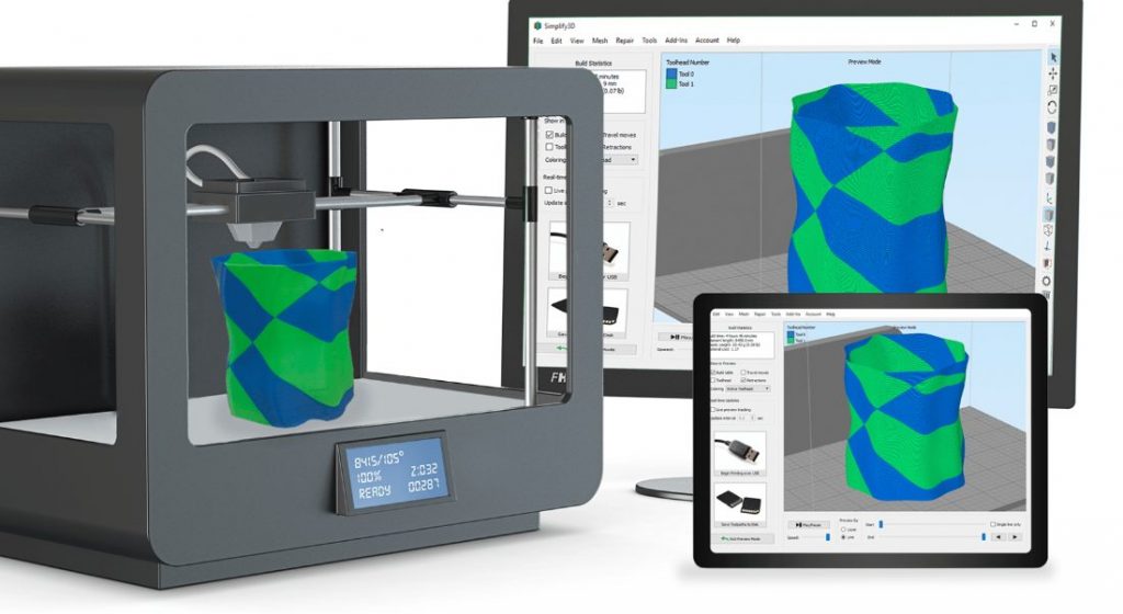
It's worth noting that if you use a text editor to open a G-code file created with a 3D slicer, it may not immediately start with G- or M-commands. For example, a slicer like Cura or Simplify3D runs the code, including some of the print process parameters defined earlier in the comments. These lines do not affect the print, but instead are a quick guide to parameters such as layer height. nine0003
Stage 1: Initialization
The first section of any program includes the preparatory tasks necessary to start printing a 3D model. Below are the first six lines of G-code initialization commands from the actual 3D print job.
G90 M82 M140 S80 M104 S200 G28 G29
As we now know, the first line tells you to use absolute positioning when moving, and the second line tells the extruder to also interpret the extrusion in absolute units. nine0003
The third and fourth lines start heating the bed and the nozzle to the set temperatures. Note that it will not wait for the target temperature to be reached, meaning the printer will automatically reset and level the table when heated.
Some initialization routines (such as the one used by the PrusaSlicer) include a nozzle cleaning process or printing a single straight line before proceeding to the 3D printing process.
Stage 2: 3D printing
This is where the magic begins. If you look at the layered G-code file, you realize that it's really impossible to understand what a nozzle actually does.
3D printing is a layer-by-layer process, so you'll find that this step involves a lot of movement in the XY plane when printing a single layer. Once this is done, one tiny movement in the Z direction will define the beginning of the next layer.
Here is an example of what G-code commands might look like in 3D printing:
G1 X103.505 Y153.291 E4.5648; movement and extrusion in the XY plane G1 X103.291 Y153.505 E4.5804; movement and extrusion in the XY plane G1 Z0.600 F3000; change layer G1 X104.025 Y154.025 F9000; movement in the XY plane G1 X95.975 Y154.025 E0.4133 F1397; moving and extruding in the XY plane
Step 3: Reloading the 3D Printer
Finally, when the 3D print is complete, some last lines of the G-code commands reset the printer to its default state. nine0003
For example, the nozzle may move to a predetermined position, the hot end and table heaters are turned off, and the motors are turned off.
M107; turn off the fan G1Z10; move the nozzle away from the print M104S0; turn off hot end heating M140S0; turn off bed heating M84; turn off the motors
Data input and output through the terminal
So far we have only talked about the fact that the computer sends G-code commands to the 3D printer (usually transmitted via an SD card). However, this is not the only way to communicate. nine0003
Some 3D printer control software, such as Pronterface and OctoPrint, allows you to interact directly with the 3D printer, in which case you can enter commands manually.
For obvious reasons, it would be impractical to print anything by sending code lines individually. But sometimes this method of communication is required for other purposes, such as obtaining valuable information for calibration or when the 3D printer does not have a display.
For example, the M105 "report temperatures" command will retrieve the current nozzle and bed temperatures (which can then be displayed by something like OctoPrint). nine0003
This link is also very useful for viewing and changing EEPROM settings that are hardcoded at the firmware level. Parameters such as motor steps / mm, maximum feedrate or PID controller can be visualized with M503 ("report settings"), changed manually and then saved with M500 ("save settings").
Writing G-code
By now you should be able to read and understand G-code much better. We recommend looking towards the following options to deepen your knowledge:
- online G-code visualization is a great tool to test your skills as you can write G-code commands and simulate them accordingly. It's actually a lot of fun!
- looking at exported G-code files from slicers should also give you some idea of how G-code works for 3D printing.
- You can use the information from the official Marlin website as a command reference.
Compatible
We hope that with your understanding of the G-code commands, you will become a more advanced 3D printer user. Although G-code is not the most complex computer language, it still requires practice and learning.
Before wrapping up this article, it might be worth talking a little about G-code compatibility.
There are many types of 3D printing firmware, and each can have a different "variant" of G-code. This can lead to serious compatibility issues, as commands that work on one machine may not work on another.


