Screwing into 3d printed parts
How do you assemble 3D-printed parts? Practical tips on threads & screws for 3D printing
What are the ideal ways to assemble 3D-printed components? This article compares different methods for designing threads for 3D printing and provides step-by-step instructions on how to install screws and other fasteners.
Threaded fasteners, such as screws and inserts, are a popular method for securing 3D-printed parts together. Threaded fasteners allow quick assembly and disassembly, granted the threading has been designed and printed properly, and provide robust connectivity so parts don’t come apart easily.
This article covers the optimal threaded fastening techniques to apply when dealing with 3D-printed parts and examines the methodology behind implementing each of them.
To learn more about the different types of threads, especially if you're also interested in CNC machining custom parts, read our extensive guide to threads .
What are threaded fasteners for 3D printing?
As a rule of thumb the minimum wall thickness around a thread should match the diameter of the fastener (e. g. an M5 fastener requires a minimum of 5mm wall thickness around the threaded hole). If the wall thickness is too low, parts can bulge and distort due to the added stress and in some cases (particularly with FDM) delamination or fracturing can occur.
The table below introduces the threaded fastening methods that are best suited to 3D printing.
| Process | Description |
|---|---|
| Inserts | Popular method used regularly that gives a strong metal-on-metal connection but requires additional components and installation |
| __Embedded nut __ | Fast method for securing components. Accurate design and print are needed |
| Self-tapping screws | One-off method for securing parts that is not optimal for repeated disassembly |
| __Cutting threads __ | Provides design freedom however correct tapping procedure is important |
| __Printing threads __ | Not suited for small threads (less than M5) and requires high printer detail/resolution to print accurately |
Note: Drilling the pilot or alignment hole to the desired diameter post-printing, before implementing any of the fastening methods discussed in this article, will typically give a more accurate diameter compared to a 3D-printed hole.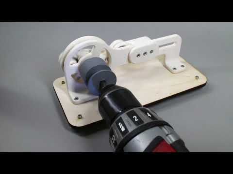
What are inserts for 3D print assemblies?
The two types of inserts that are best suited for 3D printing are heat-set inserts and tap-in inserts. Inserts provide strong metal-on-metal contact and are very easy to install. An accurate pilot hole is required, so drilling is recommended before installation.
Methodology for heat-set inserts
-
Align the insert with the pre-printed or drilled hole (for hole sizes refer to the insert manufacturer's recommendations)
-
Insert a soldering iron into the insert, heating it and the surrounding material up (avoid overheating and melting the surrounding material)
-
Slowly apply pressure, pushing the insert down into the hole to the desired depth.
Methodology for tap-in inserts
-
Align the insert with the pre-printed or drilled hole (for hole sizes refer to the insert manufacturer's recommendations)
-
Using a hammer gently tap the insert down into the hole to the desired depth.
What is an embedded nut in 3D printing?
Another method of securing 3D printed components together is to embed a nut into the component via a nut-shaped cavity (often referred to as a nut boss). This method does not require any material removal. Often determining the optimal nut boss dimensions requires several iterations. Printing small test parts to determine the ideal dimensions can save on time and material costs.
Methodology for embedded nuts
-
Measure your nut. If you do not have access to the nut a quick internet search will reveal standard overall dimensions for both metric and imperial nuts.
-
Include the desired nut profile in your CAD model . An iterative process may be required to find the best nut clearance based on printer calibration. As a starting point a 0.2 mm offset around the nut (0.1 mm on each side) should give a loose fit. This also may need to be increased for nuts greater than M12.
-
Select the appropriate cut-out depth (typically just below flush).
-
Including a drop of superglue on the back side of the nut will help secure it in place.
What are self-tapping screws?
Self-tapping screws cut a thread into a pre-drilled hole as they are screwed down. This offers a quick assembly method but is not suited for applications where parts will regularly be assembled/disassembled. Special self-tapping screws for plastic can be used that limit the radial stress on 3D printed holes lowering the likelihood of bulging, delamination or fracturing occurring.
Methodology for self-tapping screws
-
3D print or drill a hole in the desired screw location. For optimal pilot hole size consult the self-tapping screw provider. A pilot hole size that provides 75% to 80% thread engagement is a good starting point if this information is difficult to come by.
-
Assemble components to be secured ensuring to correctly align all holes where the self-tapping screws will be used.
-
Slowly screw the self-tapping screw down into the hole, ensuring it remains perpendicular to the hole during fastening.
What is thread cutting (or cutting a thread) for 3D printing?
Thread cutting (more commonly known as tapping) involves using a tap wrench to cut a thread in a pre-printed or drilled hole. Threads are regularly cut in 3D printed plastics.
Methodology
-
3D print or drill a hole in the required location of the thread. For pilot hole (tap drill) sizes that correspond to each thread size refer here
-
Using the correct size tap wrench and ensuring it remains perpendicular to the hole, slowly cut the thread regularly reversing or “backing off” to remove excess material to avoid binding.
-
Avoid forcing the tap wrench as this can lead to fractures or splitting of the 3D printed material.

-
Continue tapping to the desired depth.
Insert your desired threaded fastener before assembly to ensure a clean fit.
Cutting a thread with a tap wrench3D printing threads for assembly
The process of 3D printing threads eliminates the need for any extra steps post printing and allows parts to quickly be assembled together. Limitations on printer accuracy and resolution will govern the success of a printed thread. Threads smaller than M5 printed via FDM should be avoided with one of the other threaded fastener methods discussed in this article implemented instead.
After printing the threaded fastener should be screwed and removed from the hole several times to clean the printed thread before final assembly.
Practical advice for threads, screws & more assembly methods for 3D printing
-
For a more accurate fastener pilot hole consider drilling the hole after printing rather than printing it in the part.
-
The minimum wall thickness around a thread should match the diameter of the fastener (e.g. an M5 fastener requires a minimum of 5mm wall thickness around the threaded hole).
-
Heat-up or tap-in inserts and embedded nuts are the most popular methods for securing 3D printed components due to their simple installation, connection strength (metal-on-metal) and ease of repeated assembly and disassembly.
Curious about the cost of prototyping with 3D printing?
Our online 3D printing services Upload a CAD file for a free, instant quote
Ready to transform your CAD file into a custom part? Upload your designs for a free, instant quote.
Get an instant quote3D Printing Threads and Adding Threaded Inserts to 3D Printed Parts (With Video)
There are many ways to attach screws to 3D printed parts, including inserts, tapping, and even 3D printed screw threads.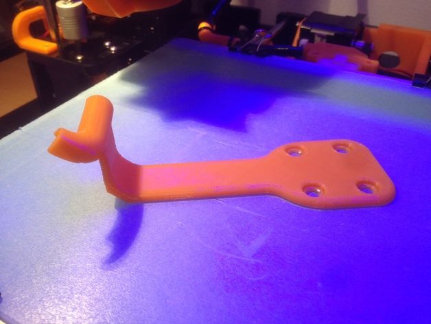
Screws are among the most popular fasteners in any material. Can you use off-the-shelf screws with your 3D printed parts? The answer is a clear yes, for both stereolithography (SLA) and selective laser sintering (SLS) parts.
In this article, we explore different methods of using metal screws with 3D printed parts, and provide some tips for incorporating screw threads directly into your 3D design.
Watch our application video about 3D printing threads and threaded inserts for 3D printed plastics.
Video Guide
Having trouble finding the best 3D printing technology for your needs? In this video guide, we compare FDM, SLA, and SLS technologies across popular buying considerations.
Watch the Videos
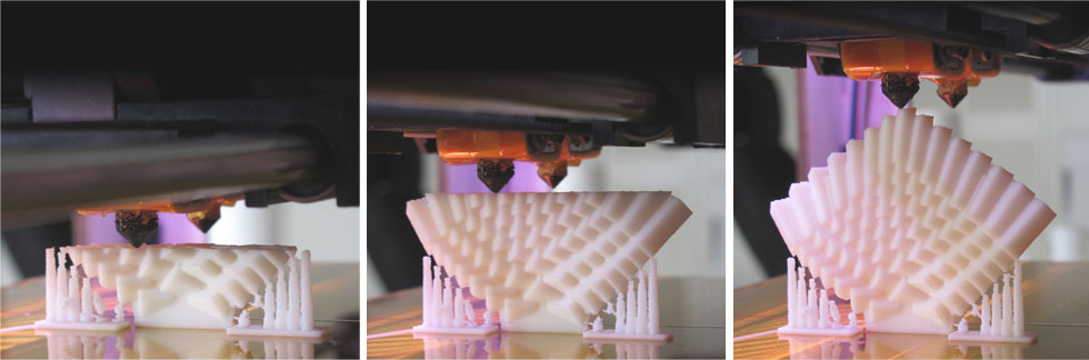
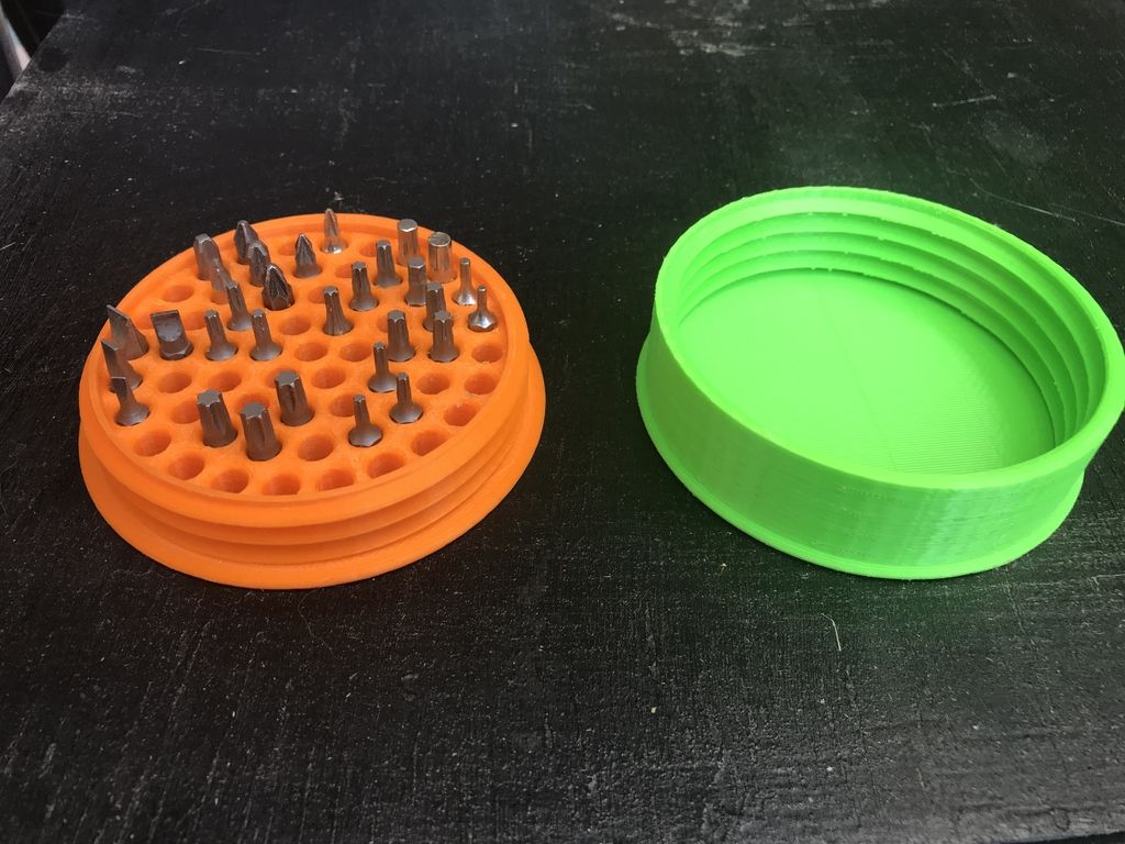
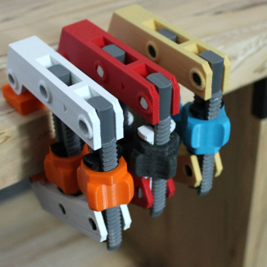
Let’s take a look at the various design options for 3D printed threads, which we’ve collected over the years within Formlabs and based on feedback from our customers. Our test part is designed to showcase all these methods at once:
We’ve grouped these options based on the type of fastening, with pros and cons of each option listed for different use cases.
Sample part
See and feel Formlabs quality firsthand. We’ll ship a free sample part printed on an SLA or SLS 3D printer to your office.
Request a Free Sample Part
In this section, we look at three ways to incorporate inserts and nuts into your completed 3D prints for strong, long-lasting fastening that stands up to multiple cycles of assembly and disassembly.
Pros
-
Very good hold into 3D printed parts
-
Metal threads are strong and wear-resistant
-
Installs with a simple press fit
Screw-to-expand inserts are cylindrical, with a slight taper and knurling on the exterior surfaces. During the design stage, incorporate a boss with a depth and diameter based on the insert’s specs into your part. Print and post-process the part as normal, following the usual steps for SLA or SLS post-processing, taking care to make sure no extra material remains inside the cavity, and install the insert with a simple press fit. Adding a screw will press the knurled surface into the surrounding printed material, creating a strong friction fit.
Tip for using screw-to-expand inserts with 3D printed parts made with SLA 3D printing: Wash the part as normal, insert the screw-to-expand insert, install a screw, and post-cure the part with the screw in place. Saving this step for last reduces the chance that the insert will crack the surrounding material when expanded.
Heat-set threaded inserts are designed to be installed into thermoplastics using a soldering iron with an installation tip. They can also be used as glue-in inserts in thermoset materials, such as SLA parts.
To install in a thermoplastic part, like one printed with SLS Powders, follow the installation instructions for your particular hardware. The typical process is to use a soldering iron, with or without a special attachment, to heat the insert, which conducts heat into the surrounding plastic. The surrounding material softens and, by pressing down with the soldering iron, you can gently press the insert into the printed part.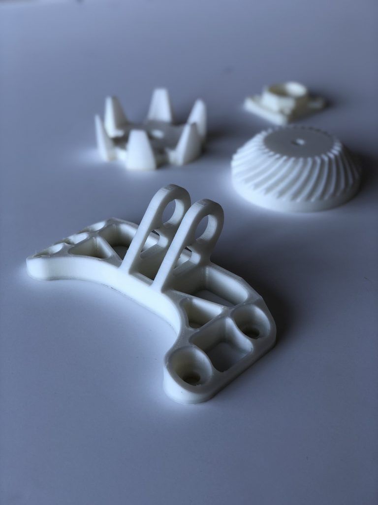 Be sure to allow enough time for the material to cool down and regain strength before installing a screw.
To install in a thermoset part, like one printed with SLA Resins, glue can be used to hold a heat-set insert in place. Unlike with traditional installation, make sure to design your boss to match the widest diameter of the insert, and use a bead of cyanoacrylate (CA) glue or epoxy to hold it in place when installed. Be sure to allow enough time for your glue to fully cure before installing a screw.
Note: In the SLS 3D printed part photographed for this article, the boss is sized for a press-fit, as we recommend here for thermoset plastics. This also works, with a drop of glue or epoxy, for thermoplastic parts, but won’t have as strong a hold as a true heat-set installation.
Although an additional step of soldering or gluing is required, heat-set threaded inserts for both SLS and SLA parts offer improved security and strength compared to screw-to-expand inserts With either method, these are a great option to gain a little extra security and strength compared to screw-to-expand inserts, although the additional step and equipment may be inconvenient.
Cons
-
Pocket or boss needs to be designed into the part, and accessible after printing
-
Depending on geometry, may require glue and curing time
Designing a pocket or boss that securely holds a nut into the part itself is another method to get metal-on-metal contact. Hexagonal or square nuts can be used, and even locking nuts are possible to accommodate. There are many design variations for this method—just make sure your pocket or boss is easily accessible (i.e. not on an interior surface) so that the nut can be installed. For extra security, a drop of cyanoacrylate (CA) glue will hold the nut in place.
White Paper
Stereolithography (SLA) 3D printers such as the Formlabs Form 3+ have high accuracy and precision, and offer a wide range of engineering materials. Download our white paper for specific recommended design tolerances.
Download the White Paper
For speed and simplicity, it might be preferable to forego inserts and nuts in favor of screwing directly into a 3D printed part.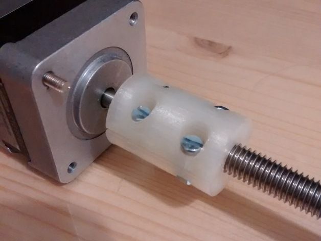 Whether tapping threads or using a self-tapping screw, off-the-shelf hardware designed for use with plastics work well with 3D printed materials like resins and thermoplastic powders.
Using a thread tap designed for plastic is a quick, economical way to add screw threads to 3D printed parts. It doesn’t require any extra design steps, and most shops that work with plastics will already have the equipment required.
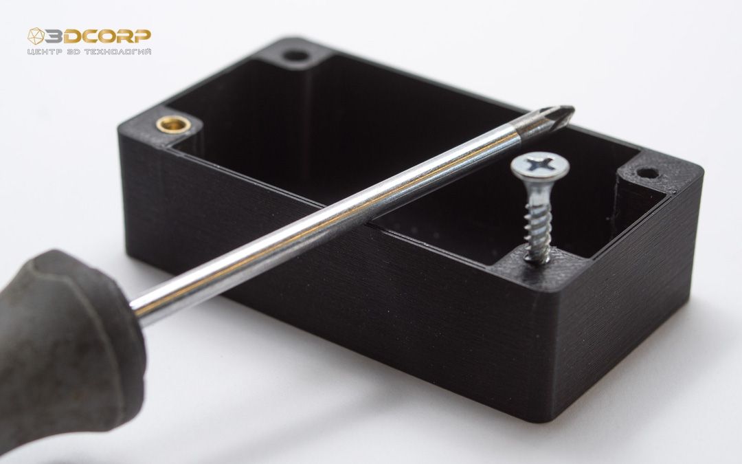
Self-tapping screws, also called thread-forming screws, can be inserted into a negative feature with no preparation work done to the part. Follow the manufacturer’s guidelines for boss dimensions.
It’s suggested to use these with materials that are ductile, or have high elongation. Formlabs Nylon 11 Powder or Nylon 12 Powder are both suitable for this, as are the Tough and Durable Resins in the Formlabs SLA material family. Brittle materials, or those with low elongation (such as the Rigid Resins in the Formlabs SLA material family), may crack when used with self-tapping screws, so take caution and wear eye protection when using these materials.
Including threaded geometries in your printed part can be effective if you follow certain guidelines. Stick to larger thread sizes, at least ¼”–20 (imperial) or M6 (metric) or larger; reduce stress concentrations with fillets; and use thread profiles that are designed for plastics. For smaller screws, the threads should be customized to create a better fastener. For example, printing a semi-circular thread profile (on screw and nut) and using a 0.1 mm offset gives better thread engagement with improved wear characteristics.
SLA and SLS 3D printing are generally preferable for this method over FDM, because they are more precise and can create parts with a smoother surface finish. Any material with particularly low surface friction, such as Durable Resin, is less likely to show wear over multiple cycles of assembly and disassembly.
When preparing your part for printing, it's important to minimize support structures on any threaded surfaces to ensure your parts will come together smoothly without additional post-processing.
There are many options for combining multiple 3D printed components using screws and threaded fasteners. From directly 3D printing threads to using off the shelf inserts, you can choose any of the methods outlined above, based on the chosen material, the number of cycles of assembly and disassembly you anticipate, the strength required, and the amount of extra steps your workflow can accommodate.
Curious to see what 3D printing material might be right for your application? Use our interactive wizard to choose the best 3D printing material or request a free 3D printed sample part to see the quality firsthand.
Explore 3D Printing MaterialsRequest a Free Sample Part
3D Printer Threads and Thread Inserts for Plastic
At Formlabs, we design various functional parts for printing on our stereolithographic (SLA) 3D printers such as the Form 3. These parts include prototypes used for our own R&D, clamps and fasteners to be used on our production lines, models to check the design before casting the final product in the appropriate material, such as nylon.
Regardless of the application, we often need to connect 3D printed components with screws and threaded fasteners. As the catalog of versatile and reliable engineering polymers grows, the differences between "imitation" prototypes and functional prototypes diminish.
This article is a guide to threading and threading 3D parts with a 3D printer. There are many ways to connect multiple 3D printed parts together, but if you need the ability to repeatedly connect and disconnect components and secure mechanical fastening, there is no real substitute for metal screws.
Do you like to see everything with your own eyes? Watch a video about 3D printing threaded connections and threaded inserts for 3D plastic parts.
White Paper
Download our white paper on stereolithography to find out how SLA printing works, why thousands of professionals use it today, and how this 3D printing technology can be useful in your work.
Download white paper
Let's take a look at some of the threading options for 3D parts we've put together based on years of Formlabs experience and your suggestions.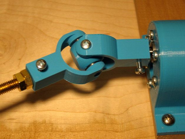 We've ranked these options, starting with the one we think is the best, with the pros and cons of each option for different use cases.
Experience Formlabs print quality first hand. We will send a free 3D printing sample directly to your office.
Request a free sample
Benefits: Strongly connects 3D printed parts without the use of glue. The metal threads are durable and reusable.
Drawbacks: Inserts may loosen as temperature rises.
3D print a sleeve blank with a depth and diameter that matches the insert specifications. Rinse with isopropyl alcohol (IPA) and allow to dry without final polymerization. Insert the insert into the sleeve with a screwdriver and use the screw to secure it completely into the plastic. Then finish curing the part to reduce the creep effect and fix the insert in the plastic even better. Performing this step last reduces the chance that the insert will break the sleeve when screwed in.
Benefits: Connects 3D printed parts very securely. The metal threads are durable and reusable.
Cons: Adhesive required (don't try to use a soldering iron!).
Threaded inserts with heat setting are designed for installation in thermoplastics using a soldering iron with a soldering tip. They can be used in acrylic models and Fused Deposition Models (FDM), but cannot be installed in SLA photopolymer parts, which bend but do not melt when heated.
Check out our detailed guide comparing FDM vs. SLA 3D printers to see how they differ in terms of print quality, materials, application, workflow, speed, cost, and more.
However, the notches and ridges on the heat set inserts make them a very effective thread fastener if you bond them with a two part epoxy or cyanoacrylate adhesive. Determine the bushing size by the largest diameter of the insert and apply some adhesive before installation.
For best results, the part must be completely dry and cured.
Benefits: Nuts are easy to match to any required screw size.
Drawbacks: Side nut slots can eliminate the need for glue, but can make it harder to support the model during printing.
Adding a hexagon socket to the nut press-fit end creates a reusable strong metal-to-metal connection. To increase the twisting force, you can choose a square nut. This nut can also be plastic or have blocking elements. If necessary, a drop of cyanoacrylate glue will help hold the nut in place, but if the design includes a side socket, there is no need for glue. Use a 0.1 mm offset around the press-in nut and clearance around the screw itself.
Benefits: Prototyping uses the same metal products as mass-produced injection molded parts. Sleeve blanks made from Tough (and Durable) polymer are unlikely to crack if you follow the screw manufacturer's sleeve design guidelines.
Disadvantages: The screws will hold tight, but the threads will not be as resistant to repeated use as metal threads. Standard resins can be used, but the bushing is more likely to crack.
Follow manufacturer's recommendations for core sizes and print with high impact engineering resins (such as our Tough Resin and Durable Resin). Before using the screws, complete the final curing. If you are prototyping an injection molded part that will use tapping or tapping screws in its final assembly, this is a good option for testing.
Benefits: No need to buy special plastic screws.
Disadvantages: The screws will hold tight, but the threads will not be as resistant to repeated use as metal threads.
We have tested screws in our Tough Resin product and found that their use is identical to that of threading screws designed for plastics. The size of the hole diameter of the threaded bushing must be in the range between the main (threaded) diameter of the screw and the inner diameter. The screw shown is a #8 screw in a 0.16" diameter hole.
Benefits: Can be used for prototyping large and custom threaded designs.
Disadvantages: Not a durable or reusable fastening solution, especially for smaller thread sizes.
3D printed threads from standard resins are better than Tough Resins because they are much harder. 3D printed threads remain relatively brittle, depending on the size of the thread, and are not recommended if the fastening system is to be used continuously and repeatedly.
Thread sizes ¼-20 or larger are generally functional without the need for post-processing. For smaller screws, the threads must be modified to provide better fastening. For example, printing a round thread profile (on a screw and a nut) and using a 0.1mm offset results in a better thread fit and improved wear characteristics. For all screw sizes, it is best to orient the parts so that the supporting structures do not touch the threads.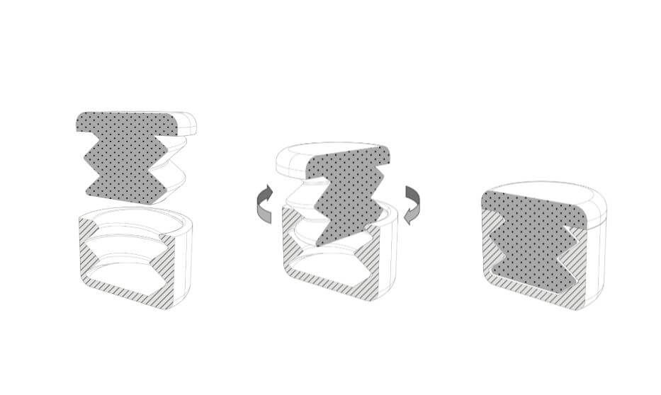
White Paper
Tolerance and fit design reduces post-processing time and simplifies assembly, as well as reduces material costs per iteration.
Learn more
We hope this guide has provided you with useful information about the mechanical mounting options that can be used for 3D printed components! If you are interested in seeing the model we use for testing, please download the STL file.
Download STL file
Parts mentioned in this manual can be ordered from McMaster using the links below:
- M3 insert with heat setting for plastic
- Brass M3 screw-in insert for plastic
- Galvanized steel hex nut M3
- Galvanized steel hex nut M4
- Threading screw 4-20 for plastic
Want to try Tough Resin, Durable Resin or any other Formlabs 3D printing material in action? Request a free sample!
Request a free print sample SLA
How to make a 3D printed part stronger durable and do not last as long as the original ones.
 We thought it would be great to learn how to somehow strengthen the printed parts, and worked on this idea a bit.
 Such stronger parts will allow us to use them in real work, under high load. Then, instead of looking for original replacement parts for broken ones in gadgets, robots, cars, mechanical toys, or for any project in development, we can simply print them.
The need for this guide came to the author when he bought bike bags on eBay. One for a friend, one for myself. The attachment of the bags meant that the handlebars were one inch (2.54 cm) thick and barely fitted a women's bike. The handlebar of the men's bicycle had a diameter of 3.15 mm, and the mount did not fit on it.
Therefore, the idea came up to make a part according to the size of the corresponding fastener by printing it on a 3D printer.
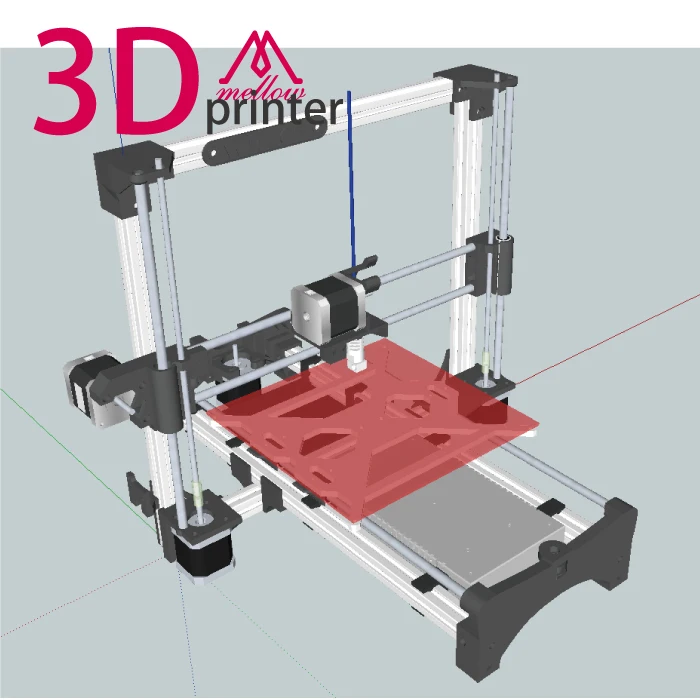
Step 1 Required part
Here is the node to be reproduced on the 3D printer.
To print something, you first need 3D model files. They, respectively, need to be found and downloaded on the Internet or developed independently. The second option seemed to be the only one possible, since it was impossible to find ready-made 3D models for such a specific part, and it was necessary to modify the one that was available so that it fit on the steering wheel.
However, everyone knows that 3D printed parts are not durable. Normally printed, this knot would not be strong enough to securely hold a heavy bag on a bumpy road. Then the idea arose to somehow strengthen this part, giving it enough strength.
The author has been involved in ship modeling for several years and had the opportunity to see how layers of fiberglass and epoxy make even thin plywood parts stronger, as a result of which they can withstand high loads without problems.
Therefore, in this work, it was decided to use fiberglass and epoxy adhesive-resin.
The original plan was to take a drawing of the part, make the necessary dimensional changes, and cover everything with fiberglass cloth and epoxy. So, let's start modeling.
Step 2. Project One
The part should look like this. All sizes are adjusted, everything as a whole is enlarged and thickened. The surfaces have also been enlarged so that fiberglass can be glued on them.
In addition, grooves are provided on each side to fill them with epoxy for extra strength. Through holes are also modeled to make it easier for the assembly parts to connect to each other and to allow fiberglass and resin to connect them from the inside.
Part printed on the Up printer and checked to see if it fits.
The type of filling was chosen as lattice, which made it possible to leave enough empty space inside the part. In a normal situation, this reduces strength, but this was done deliberately. A few more holes were drilled into the piece to allow the epoxy to penetrate and reinforce it.
Step 3 Apply fiberglass and epoxy to the first project
This is the messiest part of the job. Epoxy and fiberglass are difficult to work with.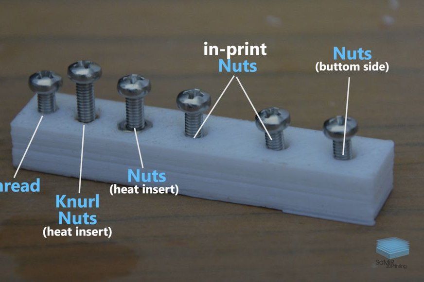 Everything sticks everywhere so that you can hardly wash it off later.
First, strips of fiberglass fabric were glued to both halves of the part to make them stick together better.
Then everything was laid out on a piece of nylon, since epoxy, fortunately, does not stick to nylon so fatally. After that, the epoxy was applied to the surface of the part, a piece of fiberglass cloth was cut to the appropriate shape and size, on top of which the epoxy glue was again applied. There was so much glue that the fiberglass became transparent.
This whole procedure was repeated for the other side of the part, after which the resin cured for a day. Even a little more, so that everything is held together tightly.
Step 4. More epoxy for additional reinforcement on the sides
It was also decided to add more epoxy in the end grooves specially provided for this.
Step 5. Project Two
During the development of the first project, it was understood that the part would be partially filled with epoxy through the additional holes drilled in it, and fiberglass impregnated with epoxy would hold it on the outside. In the process of printing the first part, the idea was born to model only its shell, and inside everything in general to make only epoxy glue and fiberglass.
And so, while the first project was freezing, it was decided to start modeling the second one. I wanted to compare both options in terms of strength and ease of manufacture. In the second project, a different approach was used to fill in two fragments of a part (two parts are needed for fastening).
The photo shows that the second project is an empty shell with walls 1 mm thick. The rounded fragment is separated from the larger one to simplify the filling process. It must then, when the epoxy hardens, be fixed with screws.
Step 6. Filling the second project with epoxy and fiber
To begin with, fiberglass was cut into small pieces, and the resulting shreds filled both parts of the part a little more than half. Then you need to add epoxy glue drop by drop and press the trim a little so that they are well saturated.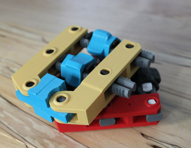
Step 7. Filling in further project 2. Fragment 1
Continue to drip and trample until all the fiberglass is saturated, after which we add more pieces of fiberglass, repeating this step until the final filling of the part. Now we fix the second fragment of the part with screws. In the end, the level of the mixture of epoxy and fiberglass should be up to the brim.
Almost the same for the smaller, rounded fragment.
Step 8. Fill in the project 2. Fragment 2
For this fragment, a slightly different approach was used: the part was not filled halfway from the very beginning. Only one layer of fiberglass was laid on the bottom, then another one - with an overlap on the edges. These layers were impregnated with epoxy until they became completely transparent, after which the following layers were laid one by one and pressed down to absorb the glue. A little epoxy was added every 2-3 coats.
The first method gave us a part with more epoxy and a little less fiberglass inside.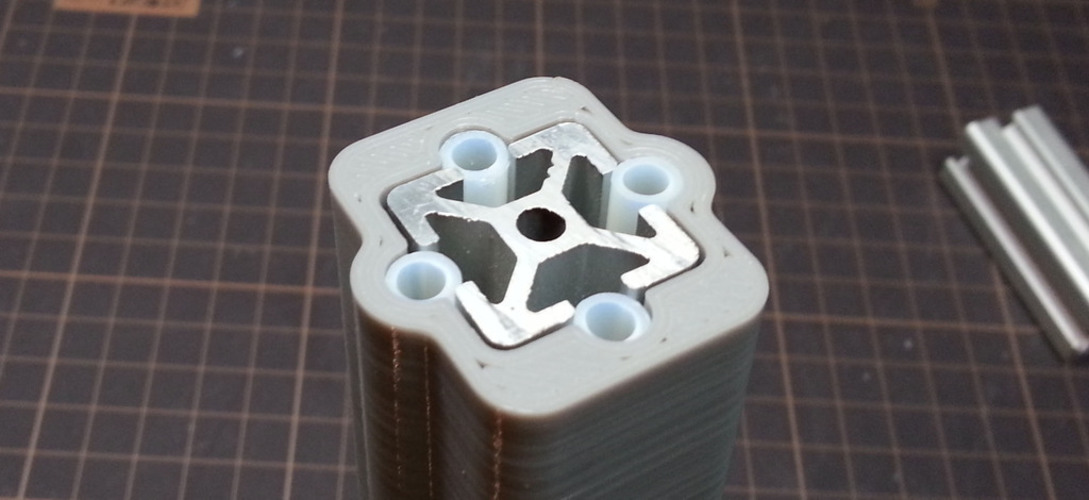 With the second method, there is more fiberglass in the part and less epoxy between layers.
Step 9. Everything should now be cured
The parts were periodically checked, more resin was added to the voids formed when the resin was absorbed. Where necessary, fiberglass was added. It took about a day to fully dry. There are epoxy adhesives on the market that cure faster, you can also add more hardener to speed up the process. However, we do not recommend this, because it will only complicate the work and prevent the glue from penetrating into all corners.
Step 10. Assembling the finished assembly
The parts turned out pretty good, especially on the second project. Attaching them to the bag went without problems. They fit great. Now you need to attach the bag to the bike.
Step 11 Remove the plastic parts
This step was not really intended. It was supposed to simply use 3D printed and reinforced parts. But when it came to sanding, the printed "skin" simply began to break off at the corners, the rest was also removed without problems.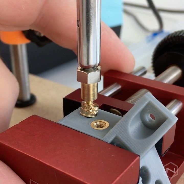 This “skin” did not give any additional strength, therefore it was almost completely removed, and the part became a composite epoxy-fiberglass.
Step 12. Summary
The part held up without problems during a 20-day trip to Sweden, Poland, Germany and Denmark. The front bag was always filled to overflowing with food, a lot of bumpy roads were passed. The parts have served perfectly and are still stronger than stone.
Here are some more useful notes.
- Interestingly, epoxy doesn't adhere very well to ABS. That is why additional holes through which it will penetrate inside and fasten the structure are simply required.
- Reinforcing a part from the outside is much more difficult than filling it. The first option takes a lot of time, but the completed part is easier. Undoubtedly, a reinforced part is much stronger than a simply printed and unreinforced part. This is easy to check if you test the reinforced and non-reinforced parts for twisting.
Learn more