Reber 3d printing
why PEKK is the ultimate choice
Aircraft door bracket printed with Kepstan® PEKK by miniFactor- The strengths of PEEK
- PEEK remains challenging to use
- What is PEKK?
- Looking to the future
The strengths of PEEK
PEEK (Poly-ether-ether-ketone) is an ultra-high performance polymer near the very top of the performance pyramid. PEEK and its cousins (PAEKs, poly-aryl-ether-ketones, including PEKK), are known for their ultra high performance in aerospace, automotive, and other industries where strength and high-temperature resistance are required. PEEK is well-suited to stock-shape extrusion and injection molding.
PEEK remains challenging to use
PEEK is probably the most widely known PAEK. It is a semi crystalline material with very fast crystallization kinetics that make it well suited for many conventional processing methods. Like most semi-crystalline materials, it undergoes a significant dimensional change (shrinkage) when it crystallizes. In traditional processing techniques, this dimensional change is easily accounted for and is widely understood, but for additive manufacturing processes, this shrinkage can result in warping and failed prints.
These rapidly formed crystalline domains are almost completely resistant to further chain diffusion and entanglements, which dramatically reduces layer to layer adhesion. To overcome these challenges, many 3D printer manufacturers have taken extreme measures to achieve reasonable part quality and print reliability. These process requirements limit the overall size and real world mechanical properties of parts printed form PEEK.
What is PEKK?
Arkema has developed a range of PEKK (poly-ether-ketone-ketone) grades, Kepstan® PEKK, offering the excellent properties of PAEKs, with a much wider and more flexible processing window.
PEKK and PEEK are very similar in structure, but with two key differences:
- PEKK has an additional ketone group replacing one ether group in the backbone. This ketone group is a stiffer bond than the ether linkage, increasing the material’s glass transition temperature. (The temperature where the polymer first begins to soften.).
- One of these ketone bonds can either be in the para (straight) or meta (kinked) position.
By controlling the ratio of straight to kinked units in the polymer backbone, it is possible to precisely control the melt temperature, crystallinity, and crystallization rate. This control enables PEKK to be processed in ways that are difficult or impossible with many similar polymers such as PEEK. This means it can be much more easily printed using FFF."
Roderick Reber - Staff technical engineer at Arkema
<p>This flexibility to tune PEKK according to a user’s needs means that this one material can serve many different purposes, and it also provides manufacturers with increased printing reliability. Fewer failed prints + less need for fine tuning of settings gives users a significant reduction in both manufacturing time and cost.</p>
This flexibility to tune PEKK according to a user’s needs means that this one material can serve many different purposes, and it also provides manufacturers with increased printing reliability. Fewer failed prints + less need for fine tuning of settings gives users a significant reduction in both manufacturing time and cost.
Along with this flexibility, PEKK provides users with even more advantages over PEEK:
- More strength at high temperatures due to a higher glass transition temperature (Tg)
- Higher compression strength
- Improved barrier performance
- Better wear and friction properties
Kepstan® PEKK polymers can be further tailored to suit specific needs with molecular weight control or the addition of carefully selected additives such as glass fibers, carbon fibers, or carbon nanotubes. Lightweight, strong, and resistant to all but the most aggressive chemicals, it can be used to replace metal components in highly demanding environments to reduce weight. PEKK’s unique properties make it the ideal high performance polymer choice for either FFF or LS processes.
These advantages mean that PEKK can be used to 3D print parts for use in highly-demanding industrial applications, whereas for PEEK the manufacturing of these has been restricted to more conventional methods. PEKK’s strength and resistance make it useful in high heat and pressure environments such as engines, and its low outgassing means it can be used in satellites and submarines. It has already been used to 3D print several components of the commercial spacecraft for crew transportation.
Looking to the future
PEKK allows greater manufacturing flexibility than other PAEK polymers. This means that the potential of 3D printed PEKK for numerous highly-demanding industrial applications is huge. As the field of 3D printing moves rapidly from simple prototyping toward industrial uses, PEKK will open up countless new manufacturing possibilities.
To accelerate application-specific use of PEKK, Arkema has developed partnerships with 3D printer developer miniFactory and filament producer Kimya. Together, they have developed a reliable supply chain and controlled process using PEKK filament to create parts for the most demanding applications. PEKK is among the strongest and stiffest polymers possible to process by FFF, including in the “Z” direction.
In summary, when choosing the material for creating components intended for highly demanding environments, the choice among high performance polymers is clear: first, PEKK offers among the best physical and mechanical properties of any material that can be processed in additive manufacturing. Second, and more importantly, PEKK allows users to choose the manufacturing method that best suits their infrastructure and end purposes.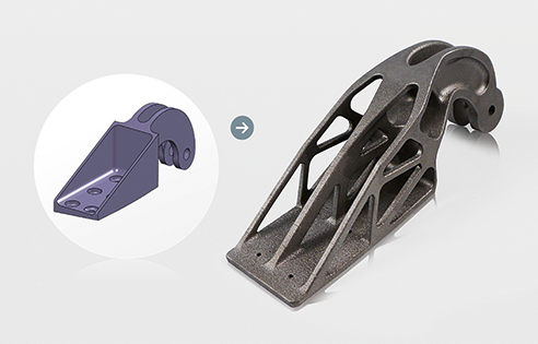
Visit our Renewable energy and energy storage page
Battery MaterialsVisit our Battery Materials page
Foranext® LiFSI and LiTDI for lithium-ion batteriesVisit our Foranext® LiFSI and LiTDI page
See also
Back to all articles
- Expertise articles
Expansion of additive manufacturing:
5 cases of industrial application08/05/2019
- Expertise articles
Elium® resin: a disruptive innovation in the world of composites?
03/07/2019
- Expertise articles
Will
thermoplastic resins transform composites industry?03/08/2019
PEKK vs PEEK: 3D printing high-performance materials
Home › Insights › PEEK vs PEKK: 3D printing high-performance materials
resource - Materials - High-performance
Table of contents
Introduction
Amorphous and semi-crystalline thermoplastics: what’s the difference?
PEEK, a highly crystalline material
The PAEK family of ultra-high performance materials
PEKK vs. PEEK
PEEK
Introduction
Over the past few years, there has been lots of buzz over 3D printers that can process PEEK (polyetheretherketone), one of the most widely known ultra-high performance polymers.
The desire to print PEEK is understandable, as it is often the go-to high-performance material for stock shape machining or injection molding.
However, many of the properties that make it so appealing for these processing techniques make it incredibly difficult to process in FFF (fused filament fabrication).
Amorphous and semi-crystalline thermoplastics: what’s the difference?
Plastic materials can be divided into two categories:
- Amorphous: amorphous polymers are simply tangled messes of long molecules. The analogy often used is a bowl of cooked spaghetti.
- Semi-crystalline: semi-crystalline polymers contain both disordered, amorphous regions as well as crystalline domains where the chains arrange into ordered patterns.
Almost all polymers used in FFF fall into the category of amorphous materials as they are far easier to process than semicrystalline materials.
Indeed, amorphous polymers undergo less dimension change when cooling, and the disordered structure allows some diffusion and entanglement between polymer chains in adjacent layers. This results in better dimensional accuracy and layer adhesion for FFF objects.
PEEK, a highly crystalline material
PEEK is a highly crystalline material with very fast crystallization kinetics. Like most semi-crystalline materials, it undergoes a significant dimensional change (shrinkage) when it crystalizes.
Its crystalline segments are almost completely resistant to further chain diffusion and entanglements. In conventional processing techniques, this dimension change is easily accounted for and is widely understood.
To overcome this, many 3D printer manufacturers have taken extreme measures to increase bed adhesion. They are also often extruding at very high temperatures to partially melt the previous layer in an attempt to make a part with acceptably low warping and decent layer adhesion.
The PAEK family of ultra-high performance materials
PEKK (Poly-Ether-Ketone-Ketone) and PEEK (Poly-Ether-Ether-Ketone) are both part of the PAEK (Poly-Aryl-Ether-Ketone) family of ultra-high performance thermoplastic polymers. This family of polymers is known for their:
- excellent strength,
- chemical resistance,
- high use temperatures,
- and low flammability.
Hence, these materials are commonly used in the most demanding applications.
PEKK vs. PEEK
PEKK and PEEK have very similar chemical structures, except for two key differences.
1. PEKK replaces one of the flexible Ether linkages with a more rigid Ketone group. This increases the glass transition temperature (Tg)– where the material first begins to soften– by about 15°C over PEEK.
2. The second Ketone group is selectively ortho (straight) or para (kinked) substituted. By varying the number of straight and kinked sections, it is possible to control the melting point and crystallization rate.
For example, a PEKK polymer with 60% straight and 40% kinked segments will melt at about 305°C and be so slow to crystallize that it is often called “pseudo-amorphous”.
The same polymer with 80% straight and 20% kinked segments will have a melting point of about 360°C, and a crystallization rate similar to PEEK.
Chemical structures of PEEK (top) and PEKK (bottom) note the varied location of the last bond on the right. Source: Arkema/Machina CorpThe tunable crystallization rate of PEKK allows an FFF user to take advantage of both the extreme performance of PAEKs and the easier processing of amorphous materials. Put simply, PEKK is easier to 3D print than PEEK (i.e. better layer adhesion), all while offering similar strength and resistance properties (i.e. better dimensional accuracy).
Most users of filament made with Kepstan ® PEKK have reported successful prints on their first try, with many commenting that it is as easy to print as ABS.
Filaments made with Arkema’s Kepstan ® PEKK are available from several independent filament converters. The material is also available in carbon fiber reinforced and electrostatic dissipative (ESD) grades.
Compare all 3D printers capable of 3D printing PEEK and PEKK in our guide to the best high-temperature 3D printers.
Optimizing the strength of 3D printed products with corners and stiffeners
News
Self-design of complex products can be both satisfying and frustrating. The simplest example of a catastrophic design error that wipes out hours of 3D printing and assembly is a lack of rigidity.
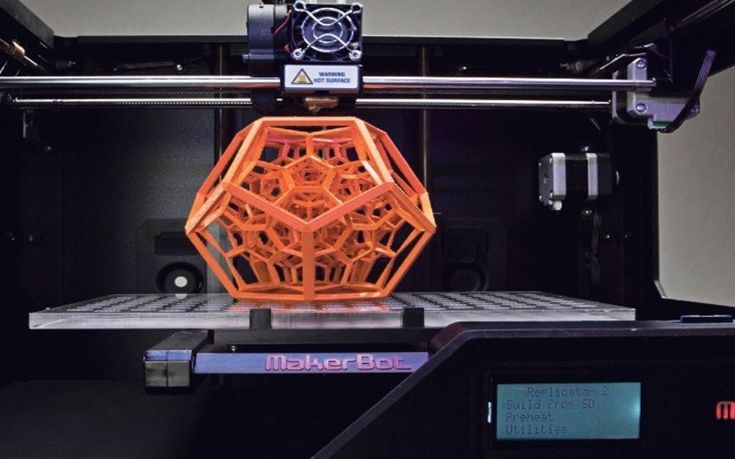 Achieving high structural strength while keeping the design as compact as possible is not easy, but it is not too difficult either. Reinforcing elements come to the rescue - ribs and corners.
 Professional designers and engineers are well aware of the problem of insufficient rigidity. One of them, Sean Thomas, an employee of the Fictiv 3D printing bureau, shared examples of the calculation and distribution of reinforcing elements on 3D printed models. To some, such measures may seem redundant, because the specificity of additive manufacturing allows you to create strong and lightweight honeycomb structures, essentially filled with spacers, but such structures do not always fit into the design, and even absorb excess volume. In addition, they are practically inapplicable in casting, and let's not forget that the tasks of 3D printers often include prototyping products for mass production using the casting method.
Fictiv is a conglomerate of maker facilities in San Francisco and surrounding areas. The bureau handles a wide range of orders, and so Sean often has to deal with the need to reinforce future castings. “Stiffening ribs and corners are often used in cast structures because the parts themselves are very sensitive to uneven, and especially excessive wall thickness. If specific parts of the model are too thick, this can lead to all kinds of defects due to twisting and shrinkage,” explains Thomas.
If printing thick structures is unprofitable or inconvenient, thin structural elements can be reinforced with stiffeners and corners. Thomas illustrates the principle with a series of experiments demonstrating the deformation and load distribution in parts with conventional and reinforced structures. One such example is shown in the illustration above: “Obviously, the design without corners is significantly inferior in strength to the reinforced version. In fact, the tensile strength of our chosen ABS variant has been reached for a conventional part. ”
”
The same principle applies to stiffeners. As Thomas demonstrates, a set of even sufficiently thin ribs has a positive effect on the rigidity of the structure as a whole. So, in a comparative test, the load on the ABS shelf reinforced with ribs reached 825.1psi - the ribs took on the rest of the load. In the usual version, the load on the surface of the shelf was all 1288psi. The nature of the deformations also depends on the presence of reinforcing elements: "The center of the model without ribs sags like a bag."
What do you need to know about using stiffeners and corners in your designs? It must be remembered that orientation plays a key role: incorrectly placed edges are completely useless. If you distribute reinforcing elements at random, the result will be only an extra waste of material without any practical benefit. “The part must be built up in the direction of the loads. If you look at the shelf from the front, then in order to increase its strength, it is necessary to increase the height with the help of ribs. The surface thickness can then be kept constant,” explains Thomas. And since the model in the illustration is more prone to longitudinal bending than transverse, then the ribs should be printed along the shelf, and not across.
When integrating reinforcing elements, do not forget about the characteristics of the filament used. “Make sure the wall thickness is within the guidelines for the process and equipment you are using,” insists Thomas. According to the author's experience, optimal rigidity is provided by ribs with a height of 60-80% of the thickness of the reinforced wall. If this is not enough, then it is better to increase the number of edges than their height. In any case, the height of the ribs should not exceed three times the wall thickness, otherwise the probability of rupture of the ribs themselves will increase without a significant increase in strength.
Tomas' full article can be found here.
Follow author
Follow
Don't want
21
More interesting articles
eight
Subscribe to the author
Subscribe
Don't want
On October 21, the solemn opening of the production site for the production of so-called. ..
..
Read more
5
Subscribe to the author
Subscribe
Don’t want
Rostec State Corporation presented at the Weldex-2022 exhibition a vacuum electron-beam...
Read more
sarkazm
6 Loading
04/01/2016
39731
68
Subscribe to the author
Subscribe
Don't want
News from the world of printing in a short line
FDplast announced the release of a free...
Read more
3D printed rib implanted in the human body
In November, cardiac surgeons at a clinic in Sofia implanted a 3DGence 3D printed rib into a patient. This is one of the first cases in the world.
Medical 3D printing
A team of doctors from Tokuda Hospital applied an innovative method to replace neoplastically altered bones in the treatment of a 35-year-old patient with a tumor formed in the rib. Ivaylo Josifov has been actively involved in sports for many years and has never had any health problems.
When he fell ill with a sore throat, the doctors gave the patient a referral for an x-ray of the lungs. To their surprise, it turned out that the man was suffering from a progressive defect in the area of the fifth right rib, accompanied by swelling and pain. It was a congenital condition that could lead to a weakened chest and stress-related problems such as difficulty breathing.
3DGence Rib Implant
Studies have shown that the best solution in this case is to remove the bone and replace it with an implant due to the risk of further disease development. The doctors chose 3D printing technology as it guarantees a perfect reproduction of the original shape of the rib, both in terms of thickness and curvature. Absolute anatomical compatibility and accuracy of the implant was required, so the decision was made to reconstruct the rib using 3D printing technology.
Our 3D printers provide high 3D dimensional accuracy which was critical in this particular medical procedure. The custom-designed rib model made it possible to insert a new element very precisely in place of the removed bone. Replacing the missing edge with a 3D printed segment of the same shape, curvature, width and thickness was made possible using a 3DGence 3D printer.Filip Turzyński, Quality Development Manager, 3DGence
In the photo: on the right - the patient Ivaylo Yosifov, on the left - a cardiac surgeon
The distributor of 3DGence in Bulgaria prepared a model of the rib for 3D printing
Work on the rib implant started with an initial 3D rendering, the bone was scanned in the hospital and the scanned image was delivered to 3dbgprint.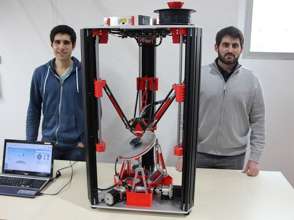 This Bulgarian company adapted the 3D model and prepared it for 3D printing. It was important that the rib fit anatomically into the other structures of the chest wall to ensure proper recovery of the body. The rib implant was fabricated using FDA-certified flexible and durable polyamide.
When we had the first model ready, we started working on its durability. Each subsequent model was analyzed and improved, until we reached the perfect 3D-printed rib.
Georgi Tolev, 3dbgprint
3D printed rib with support structures
Rib sterilization process
Prior to implantation into the human body, holes with a diameter of 3 mm were drilled in the 3D printed model to facilitate stitching and growth of connective tissue. The fin model has been properly sterilized in ethylene oxide. In addition, the printed product was sterilized by gamma irradiation and autoclaved at 140°C.


