Realsense 3d scanner
[How-to] Easy way to scan the surrounding environment in 3D (RealSense)
This article summarizes an easy way to 415D scan your surroundings using the Intel RealSense Depth Cameras (D435, D435, D515i) and LiDAR Camera L3.
Some software is required for 3D scanning (converting an object into 3D digital data), but it can be achieved with relatively simple steps.It is a procedure to scan the surrounding environment in XNUMXD and create a room with Mozilla Hubs, so we hope you find it helpful.
* This article refers to the following WEB pages
How-To: A Simple Way to 3D Scan an Environment
https://www.intelrealsense.com/3d-scanning-an-environment
table of contents
- first
- About Hubs
- Step 1: Perform a scan
- Precautions when scanning
- * Reference video
- Step 2: Convert to OBJ file
- Acquisition of color information
- Step 3: Convert to GLB file
- Step 4: Import to Hubs
- Finally
first
You need to choose different file formats to suit your purpose and software, such as 3D scanning and 3D modeling. There are several data formats and file formats in this article as well.First of all, I will give you a brief explanation.
・ PLY file format
3D image file format for storing XNUMXD point cloud data
・ OBJ file format
A simple data format that represents a three-dimensional spatial object (geometry) in one of the 3D model formats.
・ GLB file format
Binary file format of 3D models stored in GL Transmission Format (GLTF) for transmitting 3D models
After 3D scanning the surrounding environment, we aim to finally publish it on the VR-friendly platform "Mozilla Hubs" while saving the data according to the software used.
About Hubs
Hubs is Mozilla's Mixed Reality (Mojira), known for its web browser.Mixed reality) A free VR friendly platform created by the team.Through this open source social VR space, various simulated experiences are possible.Not only can you bring third parties into your space, but you can also create new rooms and import models to share them.
Step 1: Perform a scan
There are many applications for 3D scanning using Intel's RealSense depth camera, but this time we will use the file export function of "Dot3D Pro", which has a reputation for ease of use.
This demonstration uses Microsoft Surface Pro 4 (6th generation). It works on any device (desktop, laptop, etc.) as long as it is compatible with "Dot3D Pro", but you may need a USB cable of sufficient length.Also, depending on the distance to the object to be scanned, it may be necessary to consider the hardware installation location and wiring.In that respect, tablet selection has less restrictions on the installation location and hardware side, and the process of scanning the surrounding environment becomes easier.
1-1. Start scanning
Be sure to use USB 3 cables and ports when using Dot3.0D Pro.
Connect the camera to your tablet and open the software.Select the connected camera in the software settings window.
Then choose to create a new scan and select the Scan icon to start the scan.
As you move the camera, the pixels in the camera feed turn white, yellow, or green.Green means that the area has been completely scanned.For a complete scan, take the time to move around the area with small movements to fill the gap.
You can also use the host device's camera while scanning to capture the area you are scanning as a high-resolution RGB still image.You can refer to and use this still image when working with your model in a 3D package like "Blender" or "Maya" for later work.
When you are satisfied with the scan data, tap the scan button again to finish the work.Optimize your model here.It may take several minutes depending on the size of the scanned file.After optimization, scan the PLY file (3D /Point cloud file format).
Precautions when scanning
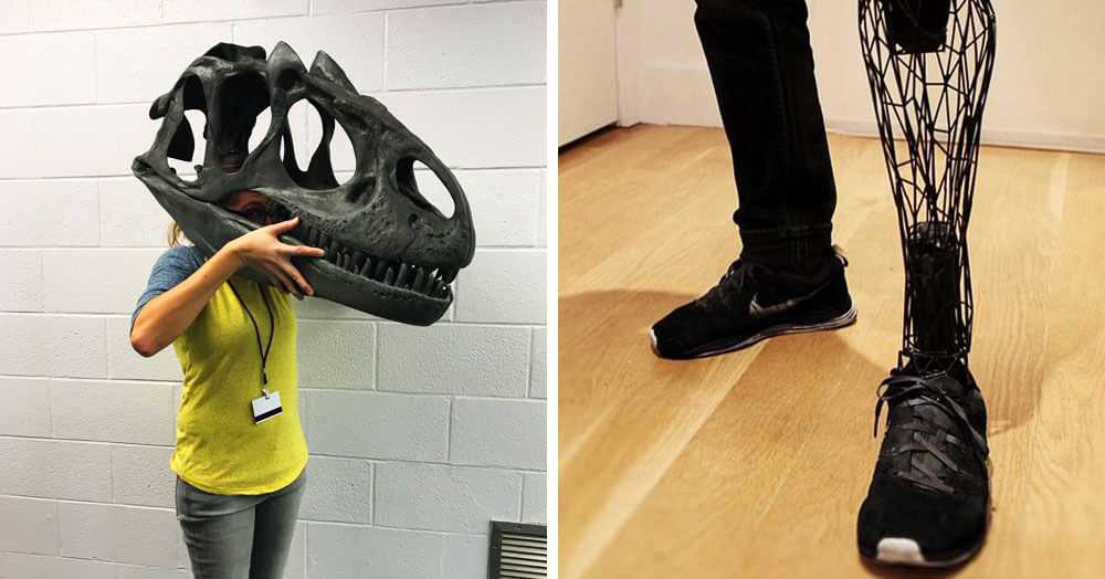
1. Avoid extremely bright places
Avoid extremely bright areas such as direct sunlight when scanning outdoors, as it can cause problems in accurately scanning the space and the resulting model may appear inconsistent. Please give me. When using the L515, scan only in indoor spaces for better model results.
2. Avoid dark and glossy materials
Objects made of materials that are very dark and reflect light, such as glossy black tables,Because there is a possibility that parallax cannot be obtained and the distance cannot be calculated.Avoid as much as possible.
See this article for a comparison of scan data in different environments.
* Reference video
The entire process of capturing and processing scan data from the newly supported Intel RealSense Depth Camera D455 and LiDAR Camera L515.
Master Class in Dot 3D ™ 4.0: Intel® RealSense ™ Handheld 3D Scanning
Step 2: Convert to OBJ file
PLY file (3D /Point cloud file format) Stores the 3D data (3D model) acquired from the 3D scanner, and can be used as it is as a 3D model.For example, 3D viewer “SketchfabYou can upload a 3D model to “and easily share (publish or share) it as 3D, VR, AR content.
However, PLY files are very large, so it is recommended to convert them to mesh format if you want to increase file processing and flexibility. The method of converting point cloud data (PLY file) to OBJ file using "Meshlab" is as follows.
2-1. Import PLY fileOpen “Meshlab” and go to File> Import Mesh on the toolbar.Import the PLY file you exported in step 1.
"Meshlab" where the imported mesh is displayed2-2. Clean the mesh data
As it is imported, it is not yet complete data.Perform some further operations to clean the point cloud data (point cloud data) and convert it to mesh data.Depending on the appearance of the file, you may mess with the settings or remove unnecessary vertices.In that case, the following procedure is recommended.
2-2-1.
Use the Select Vertices tool at the top of the toolbar to select a group of vertices.Then use the Delete the current set of selected vertices tool to delete it.
2-2-2.
Filters> Sampling> [Poisson-Disk Sampling (Go to Poisson Disc Sampling)]
Make sure "Base Mesh Subsampling" is selected on the settings screen and change the number of samples to tens of thousands (35,000 was selected here).The higher the number here, the more sophisticated the final mesh will be.Note that the number of polygons (the number of triangles) affects the operation of the mesh in other programs and applications, so do not set it too high.
There is no image here, but the layer menu on the right shows the original point cloud and Poisson disc sampling.Delete the original mesh as it is no longer needed.
2-2-3.
Filters> Point set> Compute normal for point set (Calculate surface normals )]
Change the mesh neighbor number to 16 and execute.It is trying to automatically determine the normal vector of each point (which direction each face points to) in order to generate faces with the Marching Cubes method.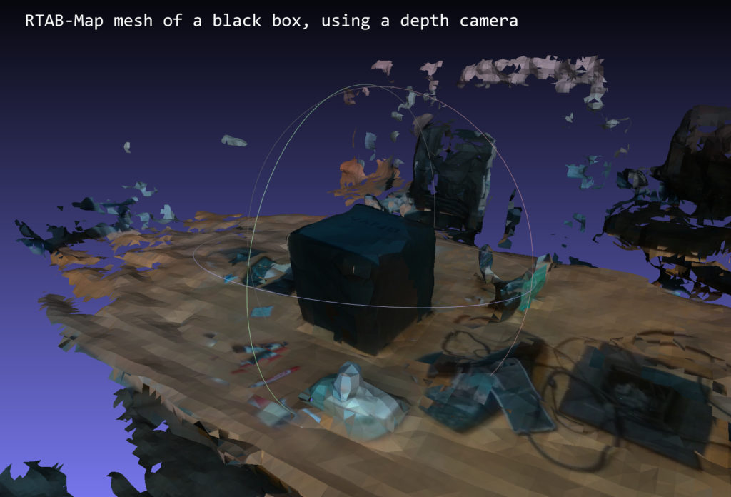
2-2-4.
Select Filters> Remeshing, Simplification and Reconstruction> Surface Reconstruction: Ball Pivoting
A single click on the up arrow in the World Unit Box next to "Pivoting Ball Radius" will auto-populate the appropriate value.When applied, a mesh will be created instead of the point cloud.Repeat the steps of going back and changing the parameters little by little until you are satisfied with the mesh you created.
Acquisition of color information
Here, we will also show you how to get the existing color information when exporting from "Meshlab".
Run Filters> Texture> Parametrization: Trivial Per triangle.If an error occurs, change the value of the border between the triangles to 1.
Execute [Filters]> [Texture]> [Transfer Vertex color to texture].At this time you will be asked to save the project.Save the texture file with the suggested name "project name".As for the save name, "_tex.png" is added to "Project name".
Export as an OBJ file to the same folder.Make sure all available checkboxes are selected.The texture file you just created is displayed in the box on the right.This file type can also be used with 3D packages such as "Unity" and "Unreal" and game engines.
The next step is to move from “Meshlab” to the open source 3D modeling tool “Blender”.
Step 3: Convert to GLB file
Open “Blender” and import the OBJ file.If you're having trouble importing a file, click View in the upper left corner of the viewport and select the Sidebar check box.
To the right of the viewport, there is a tab labeled "View".Clip start and end parameters0.01mと10000mChange to each.
Zoom in and out until you see the model.It may be upside down, so rotate it to shrink it a little.
Models in Blender: The highlighted "Rotate" tool is on the left and the "View Panel" is on the right.
Click the model displayed next.Select the "rotate" icon on the left side of the screen and use the directional ring to adjust until you can see that the floor is in the correct orientation.
At the same time, shrink the model at this stage.You can fine-tune the final size in the next step, but we recommend a size of around 10%.
You may also notice that the model has no texture.At the top right of the viewport window are several viewport shading icons. Select "Material preview" to see the color of the model.
You can also use the “Blender” editing tools to fill in the holes and remove the outer faces to make the mesh look better (there are many tutorials to help you clean the mesh, so I won't cover it here). ..
When you are satisfied with the created mesh, export it as "GLTF 2.0".The actual file extension required is the binary version of gltf, ".glb".
Step 4: Import to Hubs
Open Firefox andhubs.mozilla.com Go to and sign in to your account. Click Create a room, Choose Scene, and select Create a scene with Spoke.
Select Empty Project to create a new project.
The avatar and crater terrain that represent the spawn point are displayed.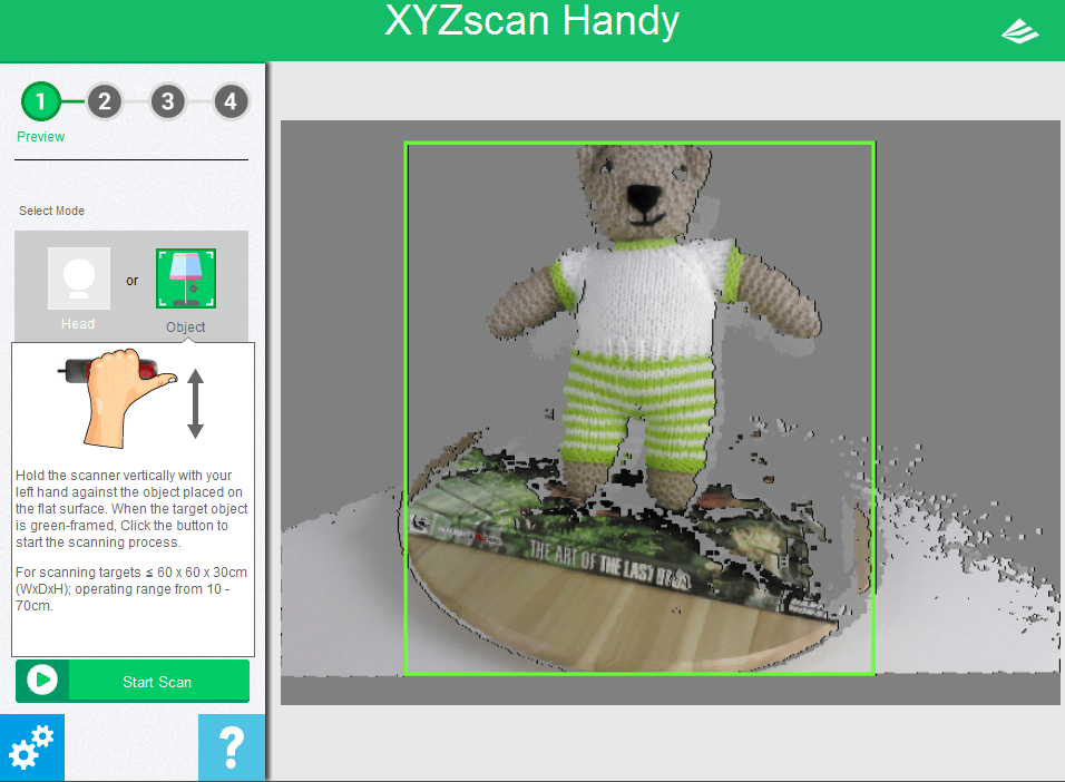 Click "My assets" in the lower left panel.Upload the .glb file you exported in step 3 here and drag and drop it into the hierarchy panel just above the crater terrain.
Use the spawn point icon and crater terrain as a guide to scale your scene.This time I scaled the mesh from its original size to 0.002.You can keep or hide the crater terrain and add objects such as lights.
Spoke window showing the final scene of the hierarchy and viewport, scaled to the spawn point model
When you're happy with the result, select Publish to hubs.Since the mesh is very precise data, it may not work well on mobile, such as when there are too many polygons (number of triangles).Ideally, the mesh should be reduced to less than 50,000 polygons during the “blender” stage to improve performance.Make sure all other performance parameters are okay and publish the scene by selecting view your scene> Create a room with this scene. To do.
In the room, you can share the link with others to show your 3D scan.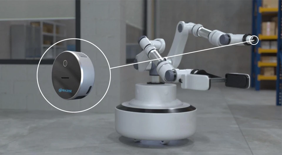 This flow should also work for point cloud objects scanned using “Dot3D Pro” or other Intel RealSense-enabled software.
This will create a social VR space where anyone can chat with the creator (you) via a browser and enjoy a virtual space using a VR headset.
The image below is the final scene I made this time.Of course, work is needed to further optimize and improve the mesh created from the original high quality scan, but we have demonstrated that this workflow can be used to create a 3D environment.
Social VR 3D scanning environment in Mozilla Hubs portal
Finally
We handle Intel's RealSense D series, LiDAR camera L515, etc. mentioned in this article.Service for R & D "Rental servicetegakariFeel free to try the actual machine.Please feel free to contact us regarding usage.
Review of The Intel RealSense D415 Using Intel RealSense SDK
3D scanning and Scan to BIM is one of the fastest growing segments of the construction industry, be it in the industrial sector or the commercial sector.
There are many competing technologies and techniques that seem to pop-up every day, photogrammetry, time of flight (depth-sensing) based scanning, and of course laser scanning are the three dominant technologies currently in use and development.
Being a small business in a developing nation, laser scanners were out of our price range, so we’ve opted for the first two techniques; photogrammetry and depth-sensing based scanners (Later we’ve tried testing Intel D515). We’ve dappled with photogrammetry but the process require huge computing power as well as very laborious photo-shoots, so we’ve decided to test the Intel RealSense platform.
Intel RealSense for scanning
This review will focus only on using the Intel RealSense D415 as a scanner and not for any other application ( robotics, object tracking, etc.).
At the time of deciding which camera to buy (late 2018), two main cameras were available; the Intel D415 and the Intel D435, other cameras like SR300 were nearly discontinued.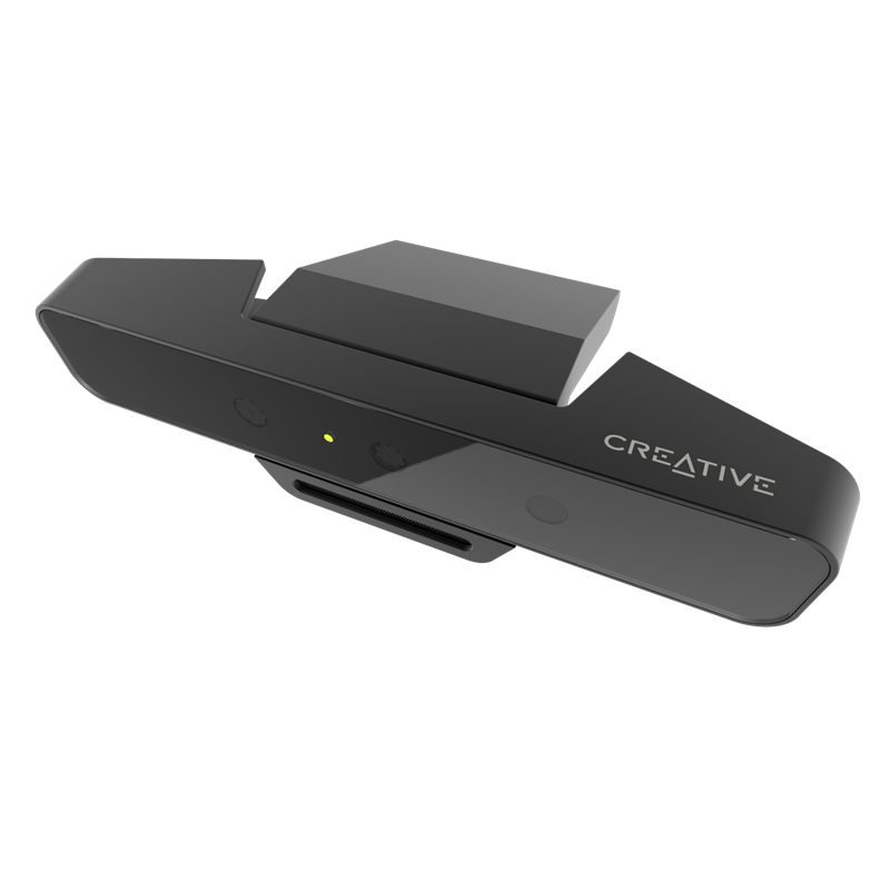
After doing our due diligence (prolonged research) we’ve found that the results from the D415 were better than the D435, it has less distortion and an overall better scan quality without many voids.
RealSense SDK
The first challenge we’ve faced was the SDK from Intel, the new SDK (V2) doesn’t have any scanning application unlike the old SDK. You can scan and get a .bag file.
First, the size of the file is huge, second, you can’t convert it to a point cloud, we’ve tried every trick using ROS, MATLAB, etc. and non was successful.
We had to rely on third-party software like Dot3D and RecFusion, there will be a separate post covering each of the software in details, for now, you’ve to understand that you can’t use the SDK to get an STL for 3D printing or a point cloud of the scan that you can use later in your BIM Software.
It’s also worth noting that you can capture a still STL using the SDK, it is like a photo but with some depth data, if that is what you seek.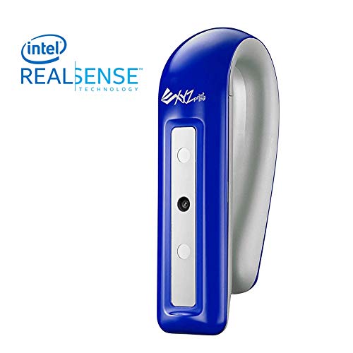
Small Scans with Intel RealSense D415
We’ve tried using both software (Dot3D and Recfusion) to scan small mechanical spare parts and instrumentation, the results were very bad (nearly unusable) in any professional capacity, the scans were so bad that I can’t include in this post, it was nothing but a blob.
Large Scans with Intel RealSense D415
We had better results with larger scans, again none of them could be professionally submitted to a client, results from Dot3D (as seen below) were better but again not for professional use. The more complex the area we were trying to scan the more voids and the more cumbersome the scan becomes. we’ve even returned to photogrammetry as for many scans the results were better and the process was easier.
Dot3D Scan with D415If you want to use the Intel RealSense D415 in a professional capacity for complex site scans, it is better to seek an alternative, but if you want to scan a room or a simple space then it is a good option.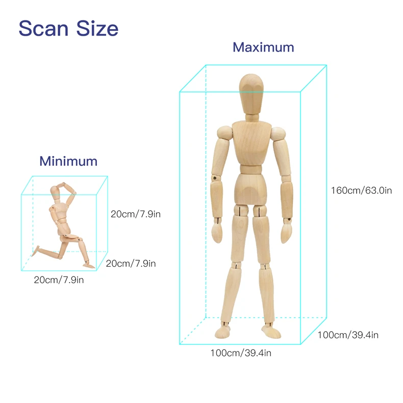 In the coming posts, I’m going to compare between RecFusion and Dot3D.
Like this:
Like Loading...
3D scanner: the illusion of accuracy
When ordering a 3D scan, a customer often asks: “ What is the accuracy of your scanner? ". It seems that the more accurate the scanner, the better. However, it is important to understand why high accuracy is required and how it can be achieved.
What is the accuracy of a 3D scanner
The accuracy of a 3D scanner is a rather vague concept. At the household level, this is usually understood as the degree of compliance of the resulting 3D model with the actual geometric dimensions of the scanned sample. nine0007
In physical terms, the accuracy can be expressed as the maximum allowable deviation from the actual size. That is, if the accuracy of the scanner is declared as 7 microns, this means that each size of the resulting 3D model will differ from the real one by no more than 7 microns.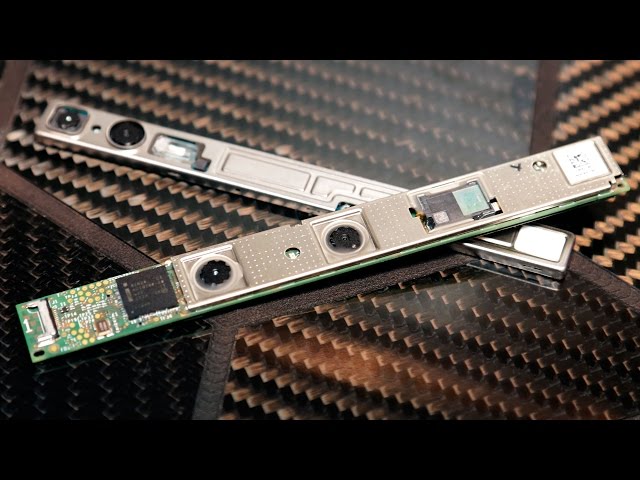
However, it is important to understand that the accuracy claimed by the manufacturer is the maximum deviation under IDEAL scanning conditions, which in reality is NEVER.
This value is obtained by performing a series of tests on an ideal sample under LABORATORY conditions, comparing the dimensions with the scanned sample, and averaging the resulting deviations. nine0007
In practice, we have a lot of deviations from the ideal, including both the objective conditions of scanning and the state of technology, and the subjective skill of the scanner and scan processor.
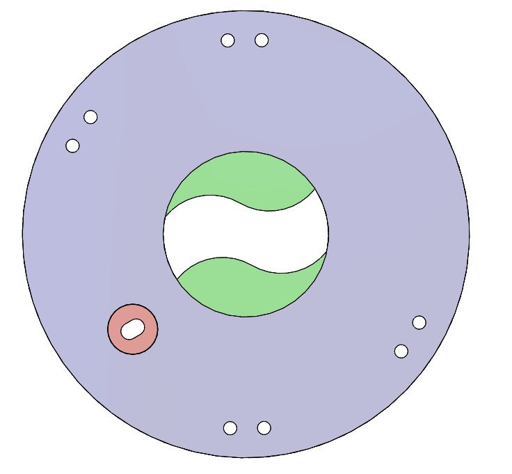
Fig.1. Comparison of the raw scanned cover model and the point cloud obtained after processing: green - exact match, red - deviations.
Fig.2. Re-comparison of the scanned and processed model after additional transformations. The result is much better, basically the whole model in the green zone. nine0007
What affects the accuracy of the final 3d model:
1.
 Characteristics of the scan object
 Due to the characteristics of scanners using structured illumination or a laser beam, the scanned object must have a number of characteristics to maintain maximum accuracy: it must be a clean, hard, white, matte object without flat sharp edges, holes, hard-to-reach places, wear, small size , so that the object is completely placed in the scanning area. nine0007
How deviation from ideal performance affects scanning, see here.
Any deviation from the ideal will degrade accuracy. For example, if the object is black, dark, transparent or shiny, it must be covered with a matting spray, which, firstly, has its thickness of about 50-100 microns, and secondly, forms microgranules on the surface, the height of which will be averaged during processing, which means , the accuracy will decrease further.
2. Technical condition of the scanner
Ideally, the scanner should be calibrated with an accuracy not exceeding the permissible one, warmed up to operating temperature, the requirements for the distance between the cameras, as well as from the cameras to the object, are met.
3. Scan conditions
A change in temperature causes the material to expand or contract according to its coefficient of linear or volume expansion. For example, a steel railway rail that is 8 meters long at 0°C will expand by almost 4 mm (or 4,000 microns!) at 40°C. nine0007
The difference between the temperature at which scanning is carried out and laboratory conditions will inevitably lead to an increase in the error.
Additionally create error:
- excess daylight from a window, uneven lighting;
- vibrations of the floor, if someone walks, or the surface on which the object is installed;
- as well as many other less significant factors.
4. Qualifications and experience of the
scanner How to apply the thinnest possible layer of Matting Spray where no spray is needed at all, how to scan in such a way that it is easier to process scans, how to ensure perfect scan stitching, how to create conditions for scanning that are close to ideal - all these issues are under the responsibility of the scanner and are highly dependent from his experience.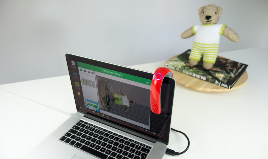 And the quality of the scanned model will depend on this. nine0007
In addition, in our practice, the scanner also performs sketches of the critical parts of the product, for the final control of the accuracy of the resulting model.
5. Qualifications and experience of the model
handlerAfter scanning and stitching, the model is sent for processing - in order to obtain a high-quality stl-file, it is necessary to eliminate debris, remnants of marks in it, properly sew up holes and make holes. At this stage, a large number of errors can be made, which will then result in deviations of the resulting model from the original sample. nine0007
If further work is carried out - obtaining a solid CAD model, the number of operations on the model increases, proportionally increasing the probability of error. It could also be a simple human error. There is a hole on the model, there is a hole on the scan, but in the final CAD model, the processor did not notice and sewed it up.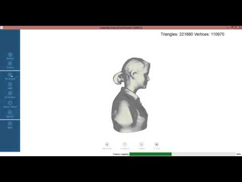
What is affected by the error in scanning
It is important to understand when accuracy matters and when it does not make any sense to pursue it.
nine0002 Accuracy is important when scanning mounting dimensions and critical surfaces, such as gear teeth or products, where the error causes a critical change in technological characteristics. But due to the problems listed above, 100% accuracy cannot be achieved even with the most advanced equipment.Therefore, when scanning critical surfaces, we always make sketches with dimensions and eliminate all scanning errors by finalizing the 3D model. Or we check the entire assembly in the 3D model together with the counterpart. In this case, it is not so important with what accuracy the scanner scanned - 5 or 50 microns, the accuracy will be 100% guaranteed. nine0007
In the case of gears, where the shape of the teeth is a complex curve, 100% accuracy can only be achieved by calculating the parameters of the gear together with its counterpart.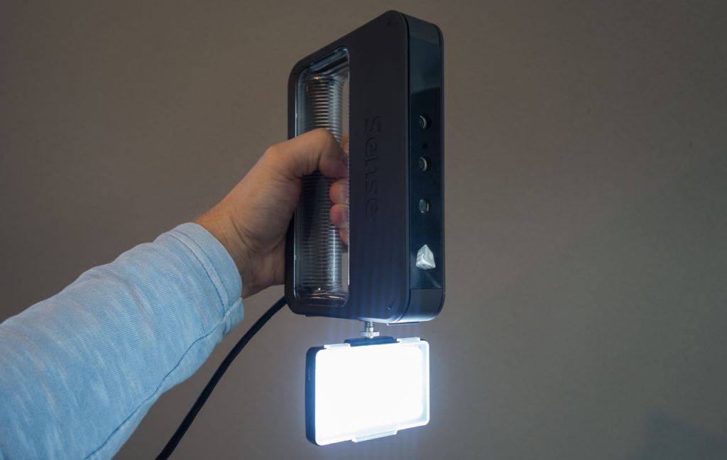
In other less important surfaces, in art products, in design elements, it is absolutely not necessary to observe micron accuracy. With a good scanner resolution, after scanning and, for example, 3D printing of a product, the original and the copy will be visually indistinguishable.
CV :
Don't chase after impressive scanner accuracy parameters, because for the vast majority of tasks, accuracy is an abstract concept that does not affect the result. You need to pay attention to factors such as:
- the resolution of the cameras, it depends on how small objects the scanner can "see";
- quality of processing and refinement of scanned 3D models to ensure the accuracy of critical surfaces. And this parameter directly depends on the experience and qualifications of the performer. nine0055
In any case, if accuracy is important during scanning, it is highly recommended to make a prototype and check its geometric characteristics before manufacturing a product from expensive material or starting a series.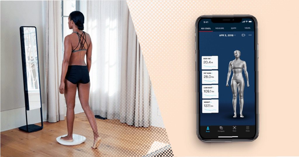
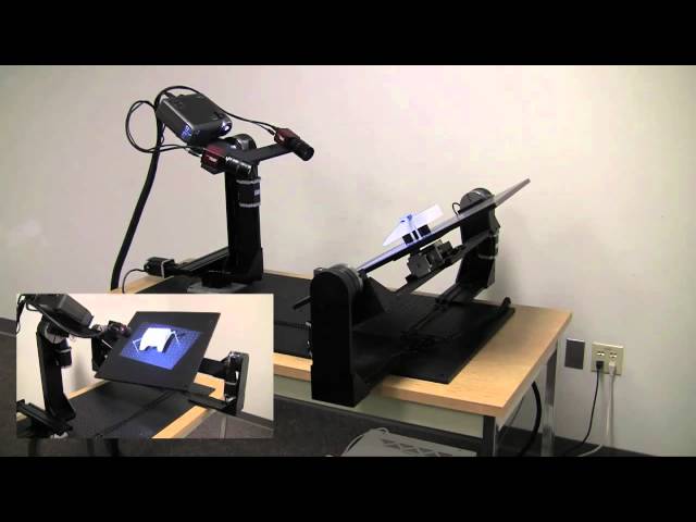
3D laser scanner on Android phone / Habr
I present to your attention a DIY scanner based on an Android smartphone.
When designing and creating a scanner, first of all, I was interested in scanning large objects. At least - a full-length figure of a person with an accuracy of at least 1-2 mm. nine0007
These criteria have been successfully met. Objects are successfully scanned in natural light (without direct sunlight). The scanning field is determined by the capture angle of the smartphone camera and the distance at which the laser beam remains bright enough for detection (during the day indoors). This is a full-length human figure (1.8 meters) with a grip width of 1.2 meters.
The scanner was made for reasons of "whether to do something more or less useful and interesting when there is nothing to do." All illustrations are based on the example of a “test” object (it is not correct to post scans of people). nine0007
As experience has shown, for a scanner of this type, software is secondary and the least time was spent on it (on the final version.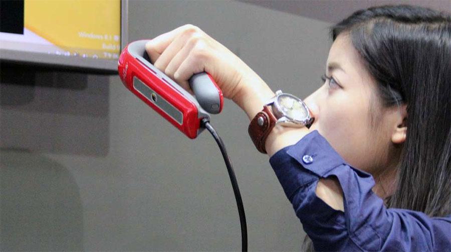 Not counting experiments and dead ends). Therefore, in the article I will not touch on the features of the software (Link to the source codes at the end of the article.)
The purpose of the article is to talk about dead-end branches and problems collected on the way to creating the final working version.
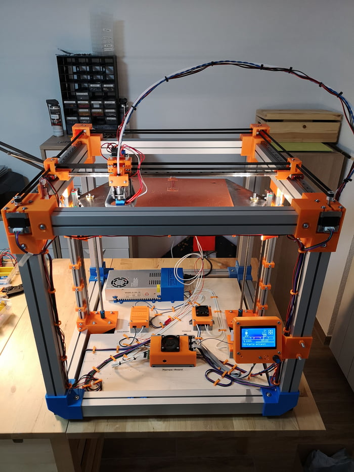
For the scanner in the final version is used:
- Samsung S5 phone
- 30mW red and green lasers with line lens (90 degree line) with glass optics (not the cheapest).
- Stepper motors 35BYGHM302-06LA 0.3A, 0.9°
- Stepper motor drivers A4988
- Bluetooth module HC-05
- STM32F103C8t board
The A4988 drivers are set to half step, which with a 15->120 reducer gives 400*2*8 steps per PI.
Select the scanning technology. nine0009
The following different options were considered.
LED Projector.
The option was considered and calculated.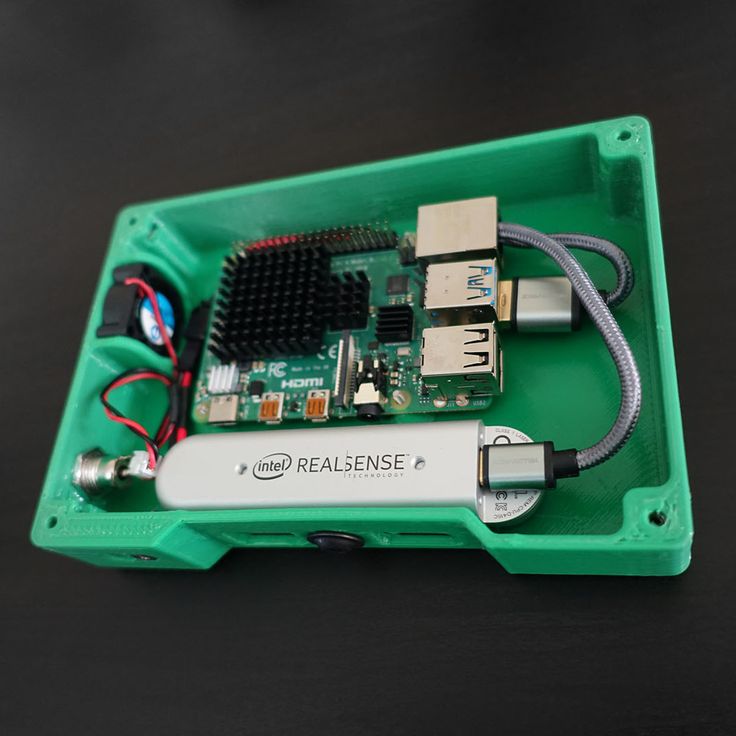 Even expensive projectors do not have the required resolution to achieve the required accuracy. And it makes no sense to even talk about cheap ones.
Mechanical laser beam sweep in combination with a diffraction grating.
The idea was tested and found to be suitable. But not for DIY performance, for reasons:
- A sufficiently powerful laser is needed so that after diffraction the marks are bright enough (the distance to the smartphone lens is 1..2 meters). And the eyes are pitiful. A laser point already with 30mW is not useful. nine0055
- 2D mechanical reamer accuracy requirements too high for DIY.
Standard mechanical scanning of the laser line on a stationary scanned object.
In the end, the option with two lasers of different colors was chosen
- Different colors of lasers make it possible to independently detect them in one frame.
- The location of the lasers on different sides of the camera allows you to get two scans in one pass.
 nine0055
 - Two scans at a time allows you to objectively evaluate the quality of the scanner alignment (scans should converge and overlap each other).
As it turned out, the last criterion is the most important. The quality of the scan is entirely determined by the accuracy of measuring the geometric dimensions and angles of the scanner. And the presence of two scans from two lasers allows you to immediately evaluate the quality of the scan:
The point clouds converged. Those. the planes captured by the two lasers converged over the entire surface. nine0007
Although from the very beginning I assumed that this was a dead-end version that did not provide the necessary accuracy, I checked it anyway with various tricks:
- The motor axis is fixed with a bearing.
- Added a friction element and a stopper for reducing gear backlash.
- An attempt to determine the "exact position" by a phototransistor, by laser illumination
The repeatability of returning to the same place of the laser line was low - 2-3 mm at a distance of 1. 5 meters. During the operation of the gearbox, despite the apparent smoothness, jerks of 1-3 mm are noticeable at a distance of 1.5 meters. nine0007
i.e. 28BYJ-48 is completely unsuitable for a more or less accurate large object scanner.
Reamer requirements based on my experience
Reamer must be a mandatory element.
Make no mistake about the 1/x step mode. Experiments have shown that in 1/16 mode on the A4988 the micro steps are not uniform. And at 1/8 this unevenness is noticeable to the eye.
The best solution for the gearbox was the use of a belt gear. Although it turned out to be quite cumbersome, it is easy to create and accurate. nine0051 The positioning accuracy (more precisely, the repeatability of the positioning of the initial position of the lasers for scanning) of the lasers turned out to be about 0.5 mm for a 5 mm laser line width at a distance of 4 meters. Those. at a scanning distance (1.2-1.8 meters) it is generally difficult to measure.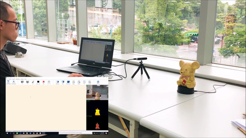
Positioning - optocouplers (Chinese noname) on a slot in the disk under the lasers.
Problems with the transmission of control signals from the phone to the laser and stepper motor control module
The bottleneck in terms of scanning speed was the control channel. Since this was a DIY leisurely development for my own pleasure, we tried all the ways to communicate with a smartphone.
Transmission of control signals via Audio jack (phone Audio jack => oscilloscope)
The slowest way to transfer data in real time. Yes, even with floating time. Up to 500 ms (!) from software activation of audio data transfer to the actual appearance of a signal in the Audio jack. nine0007
This exotic was checked because, at work, I had to deal with mobile chip card readers.
Photodiodes on the smartphone screen (a piece of the phone screen => phototransistors + STM32F103)
For the sake of interest, even such an exotic method was tested as phototransistors with a 2x2 matrix in the form of a clothespin on the screen.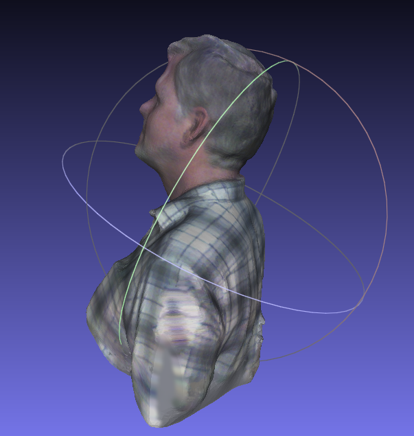
Although this method of issuing information from the phone turned out to be the fastest, it is not so fundamentally faster (10 ms vs 50ms) than Bluetooth to put up with its shortcomings (a clothespin on the screen). nine0007
IR channel (phone=>TSOP1736->STM32F103)
The method of transmission through the IR channel has also been practically tested. Even some implementation of the data transfer protocol had to be done.
But IR also turned out to be not very convenient (it is inconvenient to mount a photo sensor on a phone), and not too faster than Bluetooth.
WiFi module (phone=>ESP8266-RS232->STM32F103)
The results of testing this module were completely discouraging. The request-response execution time (echo) turned out to be unpredictably floating in the range of 20-300 ms (average 150 ms). Why and what - did not understand. I just came across an article that talked about an unsuccessful attempt to use the ESP8266 for real-time data exchange with strict request / response time requirements.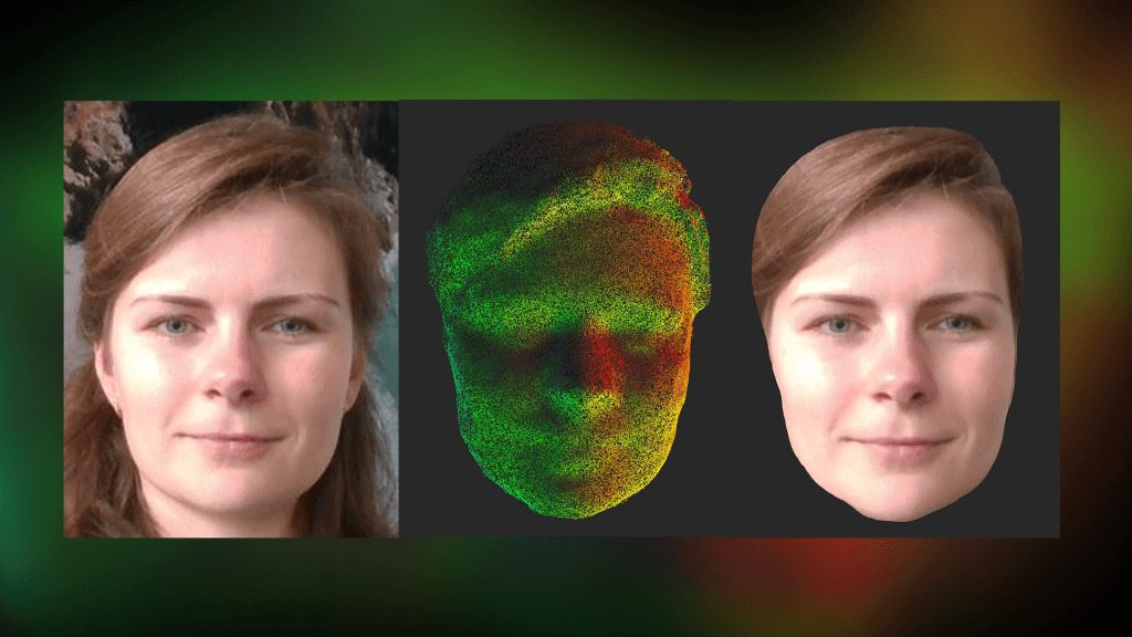 nine0007
i.e. ESP8266 with "standard" firmware TCP -> RS232 is not suitable for such purposes.
Selected control unit and signal transmission
Ultimately, after all the experiments, the Bluetooth (HC-05 module) channel was chosen. Gives a stable (and this is the most important) data transfer request-response time of 40ms.
The time is quite long and greatly affects the scan time (half of the total time).
But the best option was not achieved. nine0007
Widespread board with SM32F103C8T as control module.
Line detection methods on a frame.
The easiest way to highlight the laser lines on the frame is to use the subtraction of the frame with the laser off and the frame with the laser.
In principle, search by frame without subtraction also works. But it works much worse in daylight. Although this mode was left in the software for the sake of comparative tests (the photo of the mode is below. All other photos with the frame subtraction mode). nine0007
The practical value of the variant without frame subtraction turned out to be low.
It is possible and possible to extract the laser signal from this noisy information. However, he did not bother.
Frame subtraction works well.
All sorts of experiments with attempts to approximate the line and processing the entire frame have shown that the more complex the algorithm, the more often it "mistakes" and even slows down the processing "on the fly". The fastest (and simplest) algorithm was found to search for a laser (laser dot) on a horizontal line:
- For each point of the line, the sum of the squares of the laser color level (RGB) in the window specified in the configuration is calculated (13 px is the experimentally optimal value for the window)
- Laser point - the middle of the window with the maximum value of sums of "color" levels.
The time for processing one frame by searching for the "green" and "red lines" is 3ms.
Point clouds for red and green laser are counted separately. With correct mechanical alignment, they converge with an accuracy of < 1 mm. nine0007
Accuracy and adjustment
The accuracy was within 1 mm at a distance of 1.2 meters. Mostly due to the resolution of the phone's camera (1920x1080) and the width of the laser beam.
It is very important to make static and dynamic adjustments to get correct scans. The accuracy / inaccuracy of the settings is clearly visible when both point clouds are loaded into MeshLab. Ideally, the point clouds should converge, complementing each other.
Static parameters, set as accurately as possible once:
- Tangent of the camera's field of view.
- The length of the "arms" of the lasers (from the center of the lens to the axis of rotation).
And of course, the maximum focusing of the laser lenses at a given scanning distance and the “verticality” of the laser lines.
The dynamic parameter of the actual position angle of the lasers relative to the virtual plane of the frame has to be re-adjusted each time the phone is mixed in the mount. To do this, the setup mode in the software is made. By bringing the lasers to the center of the screen and adjusting the angle, it is necessary to set the calculated distance as close as possible to the true (measured) distance for both lasers. nine0007
Before adjustment:
After adjustment:
Pins
Such a design, perhaps, can be repeated by anyone. I cut out all the details from fiberglass on the CNC.
Of course, without a CNC router, it is difficult to make a pulley for a laser. But taking into account the fact that you need a maximum angle of rotation of 90 degrees, then with due patience, the pulley can also be cut with a needle file.
But it is still better to do it on the CNC. The requirements for axial clearance of the swivel assembly are high.