Raspberry pi lidar 3d scanner
DIY 3D scanner leverages Raspberry Pi 4, infrared camera and SLAM | Geo Week News
Frank Zhao, an engineer at PlayStation R&D who describes his position as “seeing how to make new technology fun” has taken his personal curiosity in tinkering to the 3D scanning world – creating a DIY 3D scanner that utilizes Raspberry Pi. An early adopter and experimenter with 3D printing, Zhao has recently turned to scanning and photogrammetry. In a recent project, detailed on his blog, he set out to see if infrared cameras could fill in gaps where more traditional photogrammetry techniques struggle.
After less than stellar results with a Jetson Nano developer kit and the PlayStation camera, Zhao started looking for other inexpensive and portable options.
“I was hoping for the same results as if I were to do photogrammetry with a 1280×720 camera, but with the black spots filled in instead of just a void. Also I was hoping for enough frame rate to navigate a small indoor robot.”
Raspberry Pi and Intel depth cameraThe scanner he ended up creating is contained in a 3D printed case, backed by a Raspberry Pi 4 and an Intel RealSense D415 camera. The Intel camera is depth sensing, using infrared cameras and an onboard processor to generate depth map data for feature extraction, and also includes a normal RGB camera. That’s a lot of data to push through at once – which is why using the latest Raspberry Pi 4 for this DIY 3D scanner was crucial for this to become a reality. The Raspberry Pi’s utilizes USB 3.0 (which gives the device more bandwith) and the newer ARM core has out-of-order instruction execution, which can help to speed up the process.
In terms of the software, the Pi is running a program called RTAB-MAP (Real-time Appearance-based Mapping) which is capable of performing simultaneous location and mapping (SLAM) using the same approach as commercial SLAM scanners – where overlapping points are used to extrapolate both the location and their relative positions, explains Zhao.
“RTAB-Map is a platform that uses a bunch of open source SLAM related libraries to do its mapping, and also provides a way for me to save the ‘database’ and generate 3D models. ”
”
Typical depth sensors have trouble with flat, shiny objects because of their lack of texture. The RealSense camera uses a dot projector to overlay a pattern onto the surface, so that the dots become the missing texture. The processor can then have an easier time of figuring out depth. Infrared also has the advantage of being invisible to the human eye, so it will not be distracting to light up what is being scanned with this DIY 3D scanner. This is similar to how the iPhone accomplishes its Face ID.
“Due to the amount of noise in the depth map and the lower resolution of the cameras, the resulting surface quality is poor,” commented Zhao, “However, this technique could succeed where photogrammetry fails.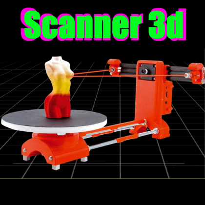 Remember that photogrammetry will fail on texture-less objects.”
If you want to attempt to replicate this yourself, Zhao provides details on his blog and github. Though the project was inexpensive, he warns that it his attempt was challenging from a software perspective (and was less straightforward to a “DIY kit“), and that he had to create his own installer script to overcome some incompatibility and dependencies. It is also not designed to be superior to commercial scanners.
“This device does not replace a commercially available 3D scanner, but it’s fun to wave around.”
Want more stories like this? Subscribe today!
About the Author
Carla Lauter
Editor, Geo Week News
Carla Lauter is the editor of Geo Week News, creating and curating content and newsletters in support of Geo Week. Before joining Diversified Communications, Carla spent 10 years on NASA and National Science Foundation funded projects focusing on Earth science and communication. She has worked on web-based outreach and online interactives for NASA Earth Science, including products for satellite missions measuring sea level, salinity and hyperspectral ocean color.
Get in touch:
Please enable JavaScript to view the comments powered by Disqus.
OpenScan DIY 3D scanner works with Raspberry Pi, DSLR, or smartphone cameras
OpenScan is an open-source DIY 3D scanner that relies on Photogrammetry and works with Raspberry Pi camera modules, compatible ArduCam modules, as well as DSLR cameras, or the camera from your smartphone.
The open-source project was brought to my attention after I wrote about the Creality CR-Scan Lizard 3D scanner. The OpenScan kits include 3D printed parts such as gears, two stepper motors, a Raspberry Pi shield, and a Ringlight module to take photos of a particular object from different angles in an efficient manner.
OpenScan ClassicThe OpenScan Classic kit above allows for 18x18x18cm scans and comes with the following components:
- 1x Nema 17 Stepper Motor (13Ncm)
- 1x Nema 17 Stepper Motor (40Ncm)
- 2x A4988 Stepper driver
- 1x Power Supply 12V/2A (5.
 5-2.5mm plug)
 - 1x Optional Bluetooth remote shutter control for smartphones
If you’re going to use the Raspberry Pi as shown on the right side of the image, you’ll also need
- Raspberry Pi 3B+ SBC or compatible,
- 8MP Raspberry Pi Camera 8MP with 15cm ribbon cable (or compatible like Arducam 16MP)
- 1x Pi Shield (either pre-soldered or solder-yourself)
- 1x Pi Camera Ringlight (optional but highly recommended), pre-soldered or solder-yourself
- 8x M3x8mm, 10x M3x12mm, 8x M3 nuts, 50x6mm steel rod, 2x 1m stepper motor cable
Alternatively, you could use a smartphone or a compatible DSLR camera with a ring light mounted on a tripod. There used to be an Arduino kit, but it has now been deprecated.
An alternative design is the OpenScan Mini pictured above with the Raspberry Pi camera and ring light attached to it, and suitable for scans up to 8x8x8 cm.
The system would then take photos from different angles under the same light conditions thanks to the ring light.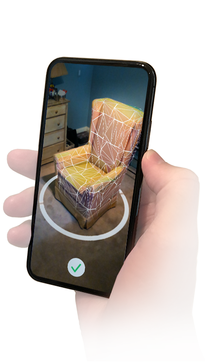 Depending on the complexity of the object, you may have to take hundreds of photos. The photos can be imported to Photogrammetry software for processing. Open-source Photogrammetry programs include VisualSFM that’s fast but only outputs point clouds, as well as Meshroom and Colmap with mesh and texture support, but you’ll need a machine equipped with a CUDA-capable GPU for both. Meshroom is the most popular and actively developed.
There’s also the OpenScanCloud that will process the photo in the cloud with minimum user intervention. It’s free thanks to a donation, but usage is limited, and whether it can stay up and running may depend on the continuous support from donations. Here’s a short demo of how this all works.
You’ll find the latest Python software for Raspberry Pi and a custom Raspberry Pi OS image on Github, and 3D files for the scanner and Raspberry Pi shield on Thingiverse.
The easiest way to get started would be to purchase one of the kits directly from the project’s shop for 107 Euros and up.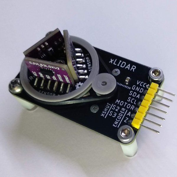 Note that a complete kit with pre-soldered boards, a Raspberry Pi 3B+, and an Arducam 16MP camera module goes for around 298 Euros including VAT.
It’s also possible to use photogrammetry without a kit, for example for larger objects, by simply taking photos of the object by yourself, but results can be mixed as found out by “Making for Motorsport” when comparing CR-Scan Lizard 3D scanner with photogrammetry using only a DSLR camera. It should be noted that both methods also required editing of the 3D model to remove “dirt” and adjust some shapes.
Jean-Luc Aufranc (CNXSoft)
Jean-Luc started CNX Software in 2010 as a part-time endeavor, before quitting his job as a software engineering manager, and starting to write daily news, and reviews full time later in 2011.
not to be confused with radar! / Amperka
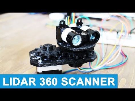
Scanning the area is one of the main tasks for unmanned robots that independently pave the way from point A to B. It can be solved in different ways: it all depends on the budget and goals, but the general essence of the engineering approach remains the same. Lidar systems have become the de facto standard for unmanned vehicles and robots. You can also attach lidar to your Arduino project!
How it works
The name LiDAR stands for Light Identification Detection and Ranging. From the name it is clear that the lidar has something in common with the radar. The whole difference is that instead of microwave radio waves, optical range waves are used here. nine0003
Let's remember the general principle of such systems: we have a device that sends out directed radiation, then catches the reflected waves and builds a picture of space based on this. This is exactly how lidar works: an infrared LED or a laser is used as an active source, the rays of which instantly propagate in the medium. A light-sensitive receiver is located next to the emitter - it picks up reflections.
Designations: D - measured distance; c is the speed of light in the optical medium; f is the frequency of scanning pulses; Δφ is the phase shift.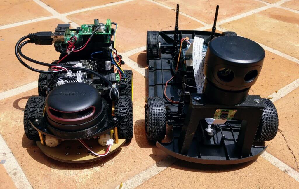 nine0016
Having received the time for which the reflected wave returned, we can determine the distance to the object in the field of view of the sensor. A similar principle for determining the distance is called time-of-flight - from the English Time-of-flight (ToF). What's next? You have different options for how to manage this data.
Optical rangefinder
The rangefinder is a special case of lidar, which has a relatively narrow viewing angle. The device looks forward in a narrow segment and does not receive extraneous data, except for the distance of objects. This is how an optical rangefinder based on the ToF principle works. The working distance depends on the light source used: for IR LEDs it is tens of meters, and laser lidars are capable of shooting a beam for kilometers ahead. Not surprisingly, these devices have taken root in unmanned aerial vehicles (UAVs) and meteorological installations. nine0003
However, a high-speed range finder can also be useful in home-made robots on Arduino and Raspberry Pi: lidars are not afraid of sunlight, and their reaction speed is higher than that of ultrasonic sensors.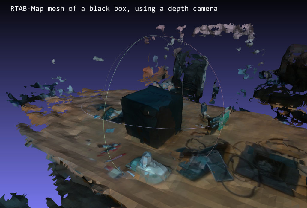 Using lidar as a space sensor, your brainchild will be able to see obstacles at an increased distance. Different models differ in range and degree of protection. Modifications in a sealed housing will allow the robot to work on the street.
Lidar Camera
The next stage of development is lidar as a 3D camera. We add a sweep system to a one-dimensional beam and get a device that can build a space model from a cloud of points in a certain viewing area. To move the scanning beam, everything is used: from rotary mirrors and prisms to microelectromechanical systems (MEMS). Such solutions are used, for example, to quickly build a 3D map of the area or digitize architectural objects.
360° scanning lidar
This is the dream of any automaker - the main sensor that replaces almost all the eyes of an unmanned car. Here we have a combination of transmitters and receivers mounted on a turntable that rotates at hundreds of revolutions per minute. The density of the generated points is such that the lidar builds a complete picture of the terrain, in which you can see other cars, pedestrians, poles and trees on the side of the road, and even flaws in the road surface or relief markings!
360° lidars are the most complex and expensive of all, but also the most desirable for developers, so they are often found on prototypes of unmanned vehicles where the cost issue is not too acute.
In conclusion
It is not necessary to wait for a bright unmanned future, because you can start your own experiments with infrared lidar on Arduino or Raspberry Pi right now. If you need a rangefinder with a working distance of up to 40 meters and an instant response, this is the right choice. And if you get confused and motorize the lidar, then you will be able to make an amateur 3D scanner based on the ToF principle. nine0003
Useful links
- Catalog of space sensors
3D laser scanner on Android phone / Habr
I present to your attention a DIY scanner based on an Android smartphone.
When designing and creating a scanner, first of all, I was interested in scanning large objects. At least - a full-length figure of a person with an accuracy of at least 1-2 mm.
These criteria have been successfully achieved. Objects are successfully scanned in natural light (without direct sunlight). The scanning field is determined by the capture angle of the smartphone camera and the distance at which the laser beam remains bright enough for detection (during the day indoors). This is a full-length human figure (1.8 meters) with a grip width of 1.2 meters. nine0003
The scanner was made for reasons of "whether to do something more or less useful and interesting when there is nothing to do." All illustrations are based on the example of a “test” object (it is not correct to post scans of people).
As experience has shown, for a scanner of this type, software is secondary and the least time was spent on it (on the final version. Not counting experiments and dead ends). Therefore, in the article I will not touch on the features of the software (Link to source codes at the end of the article.)
The purpose of the article is to talk about the dead ends and issues collected on the way to creating the final working version.
For the scanner in the final version is used:
- Samsung S5 phone
- 30mW red and green lasers with line lens (90 degree line) with glass optics (not the cheapest).
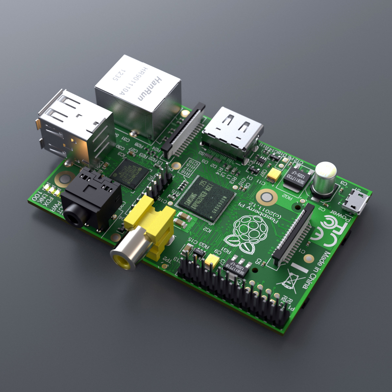
- Stepper motors 35BYGHM302-06LA 0.3A, 0.9°
- Stepper motor drivers A4988 nine0053 Bluetooth module HC-05
- STM32F103C8t board
The A4988 drivers are set to half step, which with a 15->120 reducer gives 400*2*8 steps per PI.
Select the scanning technology.
The following different options were considered.
LED Projector.
The option was considered and calculated. Even expensive projectors do not have the required resolution to achieve the required accuracy. And it makes no sense to even talk about cheap ones. nine0003
Mechanical sweep of the laser beam in combination with a diffraction grating.
The idea was tested and found to be suitable. But not for DIY performance, for reasons:
- A sufficiently powerful laser is needed so that after diffraction the marks are bright enough (the distance to the smartphone lens is 1.
 .2 meters). And the eyes are pitiful. A laser point already with 30mW is not useful.
 - 2D mechanical reamer accuracy requirements too high for DIY. nine0054
Standard mechanical scanning of the laser line on a stationary scanned object.
In the end, a variant with two lasers of different colors was chosen.
As it turned out, the last criterion is the most important. The quality of the scan is entirely determined by the accuracy of measuring the geometric dimensions and angles of the scanner. And the presence of two scans from two lasers allows you to immediately evaluate the quality of the scan:
The point clouds converged. Those. the planes captured by the two lasers converged over the entire surface.
Although from the very beginning I assumed that this was a dead end version that did not provide the necessary accuracy, I still tested it with various tricks:0003
- The motor shaft is fixed with a bearing.
- Added a friction element and a stopper for reducing gear backlash.
- Attempt to determine the "exact position" with a phototransistor, by laser illumination
The repeatability of returning to the same place of the laser line was low - 2-3 mm at a distance of 1.5 meters. During the operation of the gearbox, despite the apparent smoothness, jerks of 1-3 mm are noticeable at a distance of 1.5 meters.
i.e. 28BYJ-48 is completely unsuitable for a more or less accurate large object scanner. nine0003
Reamer requirements based on my experience
Reamer must be a mandatory element.

Make no mistake about the 1/x step mode. Experiments have shown that in 1/16 mode on the A4988 the micro steps are not uniform. And at 1/8 this unevenness is noticeable to the eye.
The best solution for the gearbox was the use of a belt gear. Although it turned out to be quite cumbersome, it is easy to create and accurate.
The positioning accuracy (more precisely, the repeatability of the positioning of the initial position of the lasers for scanning) of the lasers turned out to be about 0.5 mm for a 5 mm laser line width at a distance of 4 meters. Those. at a scanning distance (1.2-1.8 meters) it is generally difficult to measure. nine0003
Positioning - optocouplers (Chinese noname) on a slot in the disk under the lasers.
Problems with the transmission of control signals from the phone to the laser and stepper motor control module
The bottleneck in terms of scanning speed was the control channel. Since this was a DIY leisurely development for my own pleasure, we tried all the ways to communicate with a smartphone.
Transmission of control signals via Audio jack (phone Audio jack=> oscilloscope)
The slowest way to transfer data in real time. Yes, even with floating time. Up to 500 ms (!) from software activation of audio data transfer to the actual appearance of a signal in the Audio jack.
This exotic was tested because, at work, I had to deal with mobile chip card readers.
Photodiodes on the smartphone screen (a piece of the phone screen => phototransistors + STM32F103)
For the sake of interest, even such an exotic method was tested as phototransistors with a 2x2 matrix in the form of a clothespin on the screen. nine0003
Although this method of issuing information from the phone turned out to be the fastest, it is not so fundamentally faster (10 ms vs 50ms) than Bluetooth to put up with its shortcomings (a clothespin on the screen).
IR channel (phone=>TSOP1736->STM32F103)
The method of transmission through the IR channel has also been practically tested.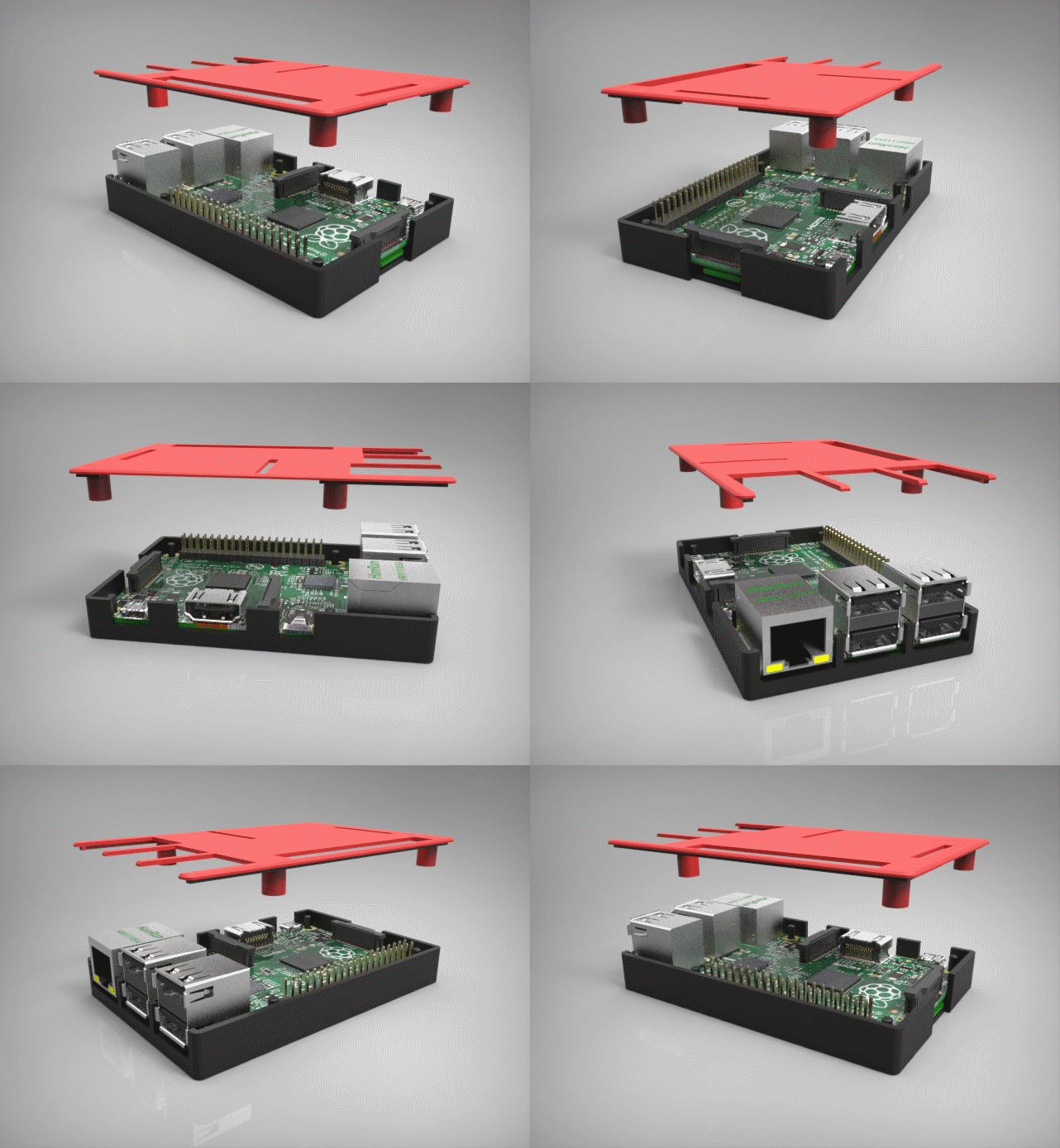 Even some implementation of the data transfer protocol had to be done.
But IR also turned out to be not very convenient (it is inconvenient to mount a photo sensor on a phone), and not too faster than Bluetooth. nine0003
WiFi module (phone=>ESP8266-RS232->STM32F103)
The results of testing this module were completely discouraging. The request-response execution time (echo) turned out to be unpredictably floating in the range of 20-300 ms (average 150 ms). Why and what - did not understand. I just came across an article that talked about an unsuccessful attempt to use the ESP8266 for real-time data exchange with strict request / response time requirements.
i.e. ESP8266 with "standard" firmware TCP -> RS232 is not suitable for such purposes. nine0003
Selected control unit and signal transmission option
Ultimately, after all the experiments, the Bluetooth (HC-05 module) channel was chosen. Gives a stable (and this is the most important) data transfer request-response time of 40ms.
The time is quite long and greatly affects the scan time (half of the total time).
But the best option was not achieved.
Widespread board with SM32F103C8T as control module. nine0003
Line detection methods on the frame.
The easiest way to highlight the laser lines on the frame is to use the subtraction of the frame with the laser off and the frame with the laser.
In principle, search by frame without subtraction also works. But it works much worse in daylight. Although this mode was left in the software for the sake of comparative tests (the photo of the mode is below. All other photos with the frame subtraction mode).
The practical value of the variant without frame subtraction turned out to be low. nine0003
It is possible and possible to extract the laser signal from this noisy information. However, he did not bother.
Frame subtraction works well.
All sorts of experiments with attempts to approximate the line and processing the entire frame have shown that the more complex the algorithm, the more often it "mistakes" and even slows down the processing "on the fly". The fastest (and simplest) algorithm was to search for a laser (laser point) on a horizontal line:
- For each point of the line, the sum of the squares of the laser color level (RGB) in the window specified in the configuration (13 px is the experimentally optimal value for the window) is calculated nine0054
- Laser point - the middle of the window with the maximum value of sums of "color" levels.
The time for processing one frame by searching for the "green" and "red lines" is 3ms.
Point clouds for red and green laser are counted separately. With correct mechanical alignment, they converge with an accuracy of < 1 mm.
Accuracy and adjustment
The accuracy was within 1 mm at a distance of 1.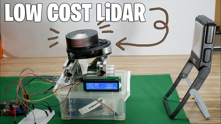 2 meters. Mostly due to the resolution of the phone's camera (1920x1080) and laser beam width.
It is very important to make static and dynamic adjustments to obtain correct scans. The accuracy / inaccuracy of the settings is clearly visible when both point clouds are loaded into MeshLab. Ideally, the point clouds should converge, complementing each other.
Static parameters, set as accurately as possible once:
- Tangent of the camera's field of view.
- The length of the "arms" of the lasers (from the center of the lens to the axis of rotation). nine0085
And of course, the maximum focusing of the laser lenses at a given scanning distance and the “verticality” of the laser lines.
The dynamic parameter of the actual position angle of the lasers relative to the virtual plane of the frame has to be re-adjusted every time the phone is mixed in the mount. To do this, the setup mode in the software is made. By bringing the lasers to the center of the screen and adjusting the angle, it is necessary to set the calculated distance as close as possible to the true (measured) distance for both lasers. nine0003
Before adjustment:
After adjustment:
Pins
Such a design, perhaps, can be repeated by anyone. I cut out all the details from fiberglass on the CNC.
Of course, without a CNC router, it is difficult to make a pulley for a laser. But taking into account the fact that you need a maximum angle of rotation of 90 degrees, then with due patience, the pulley can also be cut with a needle file.
But it is still better to do it on the CNC. The requirements for axial clearance of the swivel assembly are high. The quality of scans is 100% determined by the accuracy of manufacturing and alignment. nine0003
The scanner was doing it in the background. Sometimes with breaks for a couple of months.