Ciclop 3d scanner instructions
assembling electronic and wiring – 3 – Renzo Mischianti
by Renzo Mischianti · Published · Updated
Spread the love
Support forum
After assembling the basic mechanical components it is now time to assemble and connect all the electronic parts.
Ciclop 3D scanner electronic assemblyThe original documentation is lost, so I grab the old material from the net and I translate and rewrite in this article.
List of standard material to assembly
2 x Laser
1 x C270 Logitech® HD Webcam
1 x bq ZUM BT-328 controller board
1 x bq ZUM SCAN Power Shield
1 x Stepstick Drivers A4988 4 layers
2 x Laser cable duct printed part: 80 mm
1 x Printed part motor cable duct: 240 mm
1 x Printed part electronic cap
1 x Micro-USB Cable
1 x Power supply 12 V 1.5 A
1 x Methacrylate front pattern
1 x Printed part pattern holder
1 x Checkerboard pattern sticker
2 x Screw M3 x 10 mm – DIN 912 class 8. 8 black
2 x Nut M3 – DIN 934 class 8 black
Introduce lasers
Ciclop 3D scanner Introduce lasers parts- Assembled structure
- Laser
- Allen wrench
Prepare the camera
Logitech c270 on AliExpress
Ciclop 3D scanner prepare the camera parts- C270 Logitech® HD Webcam
- Allen wrench
Fit the camera
Ciclop 3D scanner fit the camera parts- C270 Logitech® HD Webcam without Add-ons
- Main part assembled
Fit electronics: bq ZUM BT-328 + ZUM SCAN
You can find BQ ZUM Driver Board here Aliexpress
Stepper drivers on AliExpress
Ciclop 3D scanner Fit electronics ZUM BT 328 SCAN parts- Bq ZUM SCAN power shield
- Controller board bq ZUM BT-328
- Stepstick Drivers A4988 4 layers
- Main assembled parts
Fit electronics: my PCB
Ciclop 3D scanner PCB v12 photo prospective frontYou can get full instruction for my open source PCB (fully ZUM compatible) on the previous article.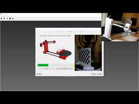
You can order 10 PCB at PCBWay for few dollars here.
Ciclop 3D scanner board v1.2 PCBWay
Cable connection and routing
Back cover
Laser wireway
Motor wireway
Power supply on Aliexpress 12v
Ciclop 3D scanner parts for cable connection and routing- Printed part for laser cable duct and motor cable duct
- Printed part electronic cover
- Micro-USB cable
- Power supply 12 V 1.5 A
- Main part assembled
Mounting the calibration pattern
Pattern holder
Pattern surface
Pattern image to print
Ciclop 3D scanner parts for mounting calibration pattern- Methacrylate front pattern
- Checkerboard Sticker
- Printed part pattern support
- Nut M3
- M3 x 10 mm screw
- Allen wrench
Assembling video
Thanks
- Ciclop 3D scanner: component printing and assembly
- Ciclop 3D scanner: production and assembly of the control PCB
- Ciclop 3D scanner: assembling electronic and wiring
- Ciclop 3D scanner: componens testing and calibration
Support forum
Spread the love
Tags: 3D Printer3D scannerArduinoCiclop 3D scanner
component printing and assembly – 1 – Renzo Mischianti
Spread the love
Support forum
I built the Ciclop 3D scanner, and I encountered some problems, such as the disappearance of the documentation from the web, now it is more difficult to find materials and components and more, I hope to allow others to overcome the problems I have had in this series of articles.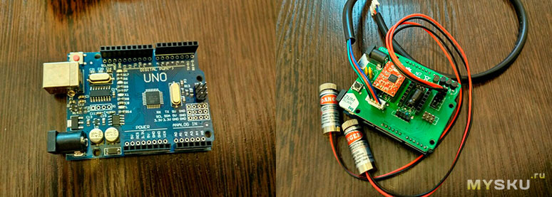
In this article I enter all the steps for 3D printing and assembling the structure, I have made some corrections to simplify the process.
Printing and Assembly Parts
The original documentation has disappeared from the internet, so I retrieve some documents in exotic languages and take the photos to write this assembly tutorial.
- 1 x Ball bearing 16014
- 1 x Black methacrylate disc Ø200 x 8 mm
- 3 x Bearing anchor printed part
- 1 x Non-slip surface Ø200 mm
- 2 x Black threaded rod M8 x 400 mm
- 1 x M8 x 292mm Black Threaded Rod
- 4 x Black threaded rod M8 x 170 mm
- 1 x Printed part of motor bracket
- 1 x Camera Bracket Printed Part
- 2 x Printed laser holder part
- 1 x Printed part of motor-disc socket
- 1 x Nema bipolar stepper motor (1.7A 1.8 deg / step) with connector *
- 7 x Screw M3 x 10 mm – DIN-912 class 8.8 black
- 3 x Screw M8 x 30 mm – DIN 931 class 8 black
- 3 x M3 nut – DIN 934 class 8 black
- 28 x M8 nut – DIN 934 class 8 black
- 18 x Washer M8 – DIN-125 class 6 black
- 6 x Non-slip silicone drops
- 1 x Allen key
Disk mounting
I created a simple STL to allow you to print the disc with the 3D printer to replace the methacrylate one, refer to “3D Printed base for Ciclop 3D Scanner“.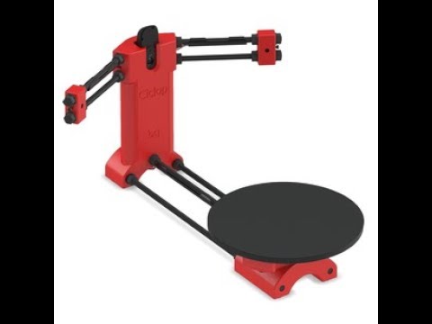
Disk holder
Bearing clip
Here the list of material.
You can find here Aliexpress Ball Bearing 16014
Ciclop 3D scanner disk mount parts- Disc holder printed part
- Bearing anchor clip
- M8 x 30 mm screw
- Ball bearing 16014
- Methacrylate disc Ø200 mm
- Non-slip surface Ø200 mm
Hold the disc (5), on its bracket (1) and bearing anchor clips (2) together when tightening each screw.
To tighten the screws use a 13 mm spanner.
Assembly of the structure: preparation of the rods
Ciclop 3D scanner rod mount parts- Newly assembled elements
- Nut M8
- Camera support printed part
- Printed motor support part
Insert the screw and nut like the image.
Ciclop 3D scanner rod mount assemblyAssembly of the structure: thread central rods
Camera holder
Motor holder
Ciclop 3D scanner thread central rod mount parts- Threaded rod just assembly
- Nut M8
- Camera bracket printed part
- Printed motor support part
First insert the central and shorter rod into the motor mount, then fit the two longer rods at each end.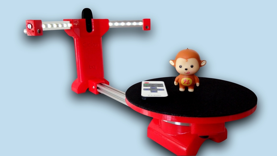 The nuts must snap into the holes underneath each piece. If not, file the gap a bit.
Assembly of the structure: preparation of the lasers support rods
Ciclop 3D scanner laser support rod parts- Black threaded rod M8 x 170 mm
- Nut M8
- Washer M8
Assembly of the structure: thread lasers rods
Ciclop 3D scanner threaded rods parts- Assembled structure
- Threaded rods just assembled
- Nut M8
- Allen wrench
Insert the Allen key (3) to retain the nut, put it in place and screw the rod into the nut.
Ciclop 3D scanner thread laser rods assemblyAssembly of the structure: prepare lasers part
Another problem is that you can probably find a low cost laser that don’t fit on orginal holder.
The common laser is 12mm laser.
You can find laser here AliExpress - eBay
So you must use this 3D printed variant.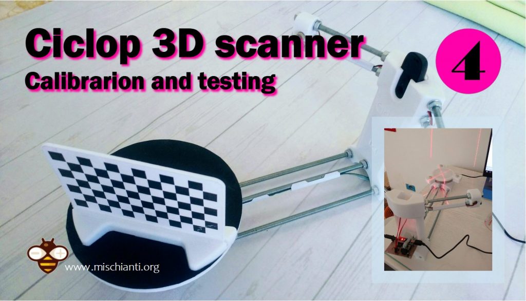
Another problem is to stop the rotating part, I think the better solution is to use a rubber band, as you can see in the pictures.
Original laser holder (For the laser I posted use previous file)
Ciclop 3D scanner prepare laser parts- Printed part of laser holder
- M3 x 10 mm screw
- M3 nut
- Allen wrench
Insert the nuts into the side holes. They must enter very fair. If not, file the gaps a bit.
Ciclop 3D scanner prepare laser parts assemblyStructure assembly: adjust lasers parts
Ciclop 3D scanner adjust laser parts- Basic structure assembled
- Laser holder just assembled
- Washer M8
- Nut M8
Assembly of the structure: prepare socket piece
Shaft coupling
Ciclop 3D scanner prepare socket piece parts- Printed part of motor-disc socket
- M3 X 10 mm screw
- M3 nut
- Allen wrench
Frame assembly: prepare Nema motor
Ciclop 3D scanner prepare nema motor parts- Nema motor (1.
 7A 1.8 deg / step)
 - Structure already assembled
- M3 x 10 mm screw
- Allen wrench
Assembly of the structure: join the socket and the disc
Ciclop 3D scanner join the socket and the disc parts- Socket assembled
- Main structure
- Disk structure
- Allen key
Assembly video
There are a lot of video also, the official one is this.
Documentation
Thanks
- Ciclop 3D scanner: component printing and assembly
- Ciclop 3D scanner: production and assembly of the control PCB
- Ciclop 3D scanner: assembling electronic and wiring
- Ciclop 3D scanner: componens testing and calibration
Support forum
Spread the love
Read ""How to defeat the Cyclops": how to assemble and debug the 3D scanner that was installed in your school" - Dmitry Usenkov
Cyclops, or, more precisely, Ciclop is a 3D scanner for scanning small objects. This model (with a turntable and one or two lasers - Fig. 1) has been developed for a long time and is used by many "home-made people" - especially since all the plastic parts of the structure are printed on a 3D printer. It was these scanners made by the Spanish company BQ that were delivered to Moscow schools in the summer of 2017 along with Hephestos 3D printers under the Technosphere of the Modern School project (read about this project and the assembly of Hephestos 3D printers in another brochure of this series - "The Taming of Hephaestus": how to assemble and debug a 3D printer that was delivered to your school - https://www.litres.ru/dmitriy-urevich-usen/ukroschenie-gefesta-kak-sobrat-i-otladit-3d- printer-k&lfrom=508959676 ).
The principle of operation of the scanner is quite simple: a laser beam in the form of a thin vertical strip hits the original object mounted on a rotating table, and due to the surface irregularities of the object (protrusions or depressions), the light strip is distorted, becomes bent, broken or broken.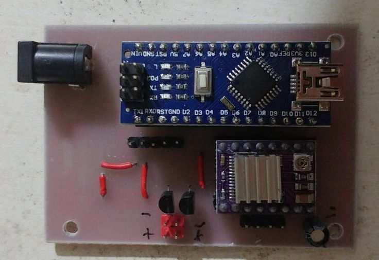 Software (Program Horus - this time the developers decided to turn to ancient Egyptian mythology instead of ancient Greek) processes the image coming from the webcam and, due to changes in brightness and contrast, highlights this bright line against the general background. And then, according to the shape of this line, the corresponding section of the surface of the object is determined (calculated). At the same time, the table rotates with a stepper motor, and the scanner gradually “copies” this object into a digital model, forming a point cloud. (In principle, one laser is enough for scanning, but you can use two at once to speed up the work and increase the accuracy of the scan.)
Like the Hephaestus, the Cyclopes were delivered to schools as a set of parts, in the expectation that there would be specialists in schools who could assemble and set up this equipment - therefore, in most cases, this equipment is most likely gathering dust somewhere in a warehouse . However, assembling and setting up a Ciclop scanner is not that difficult (and much easier than a 3D printer anyway).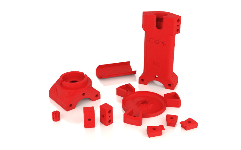 Let's get on with it.
1. Assembly
We note right away: unlike the Hephestos 3D printer kits for the Ciclop scanner, there is no printed (paper) assembly instruction. There are only electronic manuals that can be found on the manufacturer's website - BQ:
- assembly manual for the whole structure and turntable - https://storage.googleapis.com/bqcom15.statics.bq.com/prod/resources/manual/Ciclop_QSG_01_EN-1484575721.pdf
End of introductory fragment.
Text provided by LitRes LLC.
Read this book in its entirety by purchasing the full legal version on LitRes.
You can safely pay for the book with a Visa, MasterCard, Maestro bank card, from a mobile phone account, from a payment terminal, in an MTS or Svyaznoy salon, via PayPal, WebMoney, Yandex.Money, QIWI Wallet, bonus cards or in another way convenient for you. nine0007
DIY Cyclops assembly and laser scanning software
Greetings to all.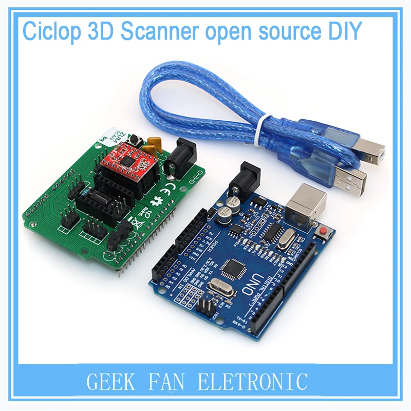 Today is a small review of the Ciclop desktop scanner.
Once again, the store offered to take something for review. Since I have long been interested in the question of using this thing for the needs of decorative 3d printing, I chose a scanner.
So, the scanner itself was developed by the Spanish company BQ, which has now ceased its support (allegedly due to Chinese fakes, but it is doubtful. Now the American CowTech also sells this scanner. The source codes for 3d printing of parts of the scanner are freely available at Thingiverse (there are also links to software and electronics).0007
Links to full documentation sets:
www.cowtechengineering.com/downloads
www.bq.com/ru/support/ciclop/support-sheet there are several points:
1. It is not worth rushing to tighten all the nuts - you still have to adjust the geometric dimensions - the convergence of lasers in the center of the site, the distance to the turntable.
2. In my stand, the camera “dangled” a little, by a fraction of a millimeter - but that was enough to skew the picture. Eliminated by laying foam material. nine0039 4. The turntable was transparent and uncoated (as in the original) - I painted it with plastidip.
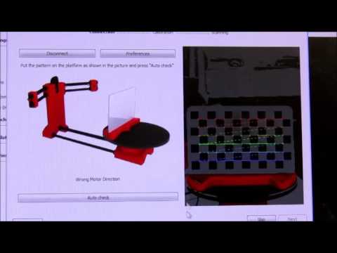
5. Check the calibration checkerboard patterns. I don’t know how they printed the one from my kit - but the proportions of the squares were violated. I took it from the Internet and reprinted it myself.
6. The focus of the camera is not adjusted to the distance to the platform. He removed the cover and twisted the focus in place.
88. The economy is managed by the "native" Horus software from BQ.
After assembly, the scanner went through calibration procedures in the native Horus software.
Since by this point I already knew that the quality of scanning is very much dependent on the quality of lighting (stability, diffuseness, color temperature), I took care of having a small lightbox in advance in order to at least provide more or less comparable conditions for samples.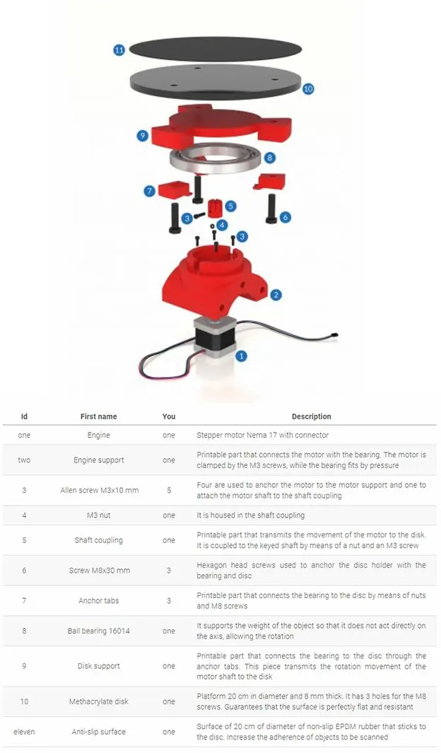
Having selected the "candidates" for the samples, I got ready. nine0039
Requirements for the object are stated as follows:
1. The object must be larger than 5x5 cm but smaller than 20x20 cm
2. The object must be opaque and still
3. The object must weigh no more than 3 kg
Difficult to scan:
1. Shiny, luminous objects
2. Too dark objects
3. Objects with a blurred surface (eg soft toys)
The result of the scan is a cloud of points in PLY format (which must then be converted to a surface). Here is a guide for post-processing the cloud and preparing the STL file. nine0007
After reading the scan optimization guide, I decided to try with a simple cylindrical object.
After several attempts, I was convinced that I had a common problem - mismatches in the point clouds from the right and left lasers, and the issue with proportions.
Nothing worthwhile about this except for trying to calibrate the webcam settings (they are not calibrated when the calibration wizard is running) could not be found (a dude named Jesus from BQ support has not answered questions for a long time).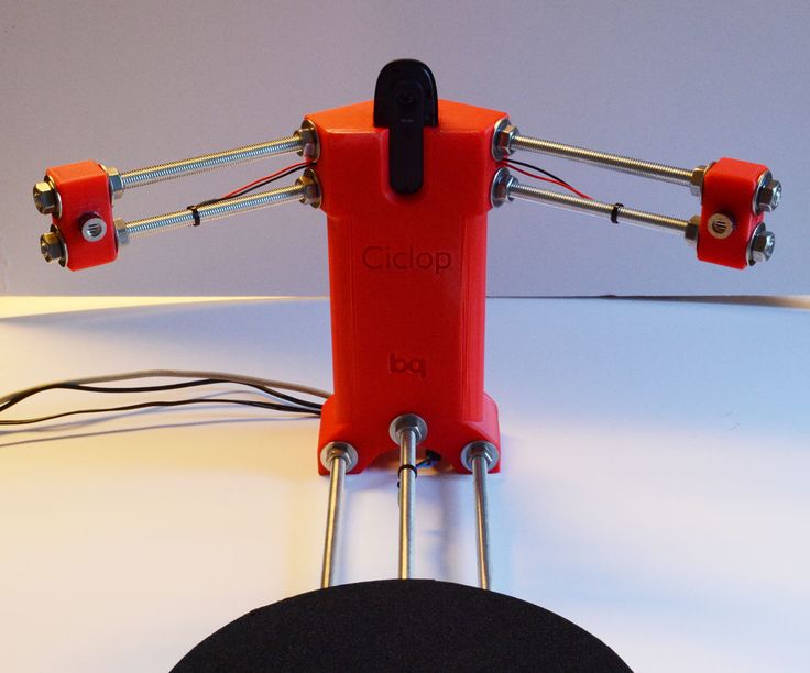 To do this, you need to take several shots with different positions of the calibration table. Done. The situation has improved, but not completely. nine0039 I had to manually edit the calibration file (calibration.json in the Horus-a folder) and by trial and error, scanning a cylindrical object, to achieve the coincidence of the clouds.
And everything seems to be ok:
But no - on complex objects, cloud fragments still sometimes do not coincide, moreover, many "blind" zones are formed:
impossible, at least with regular lasers. nine0007
You can, of course, continue experimenting with scanning with individual lasers and trying to combine all this economy in third-party software, and then try to bring it into a viable form for STL.
All this is reminiscent of a joke about boats in bottles.
-How do you make boats in bottles?
-I put sand, silicate glue, sticks into the bottle and shake it.
It turns out all sorts of shit, and sometimes boats.
In general, I realized that I am not an adept of such creativity, and I have a suspicion that it is easier to model objects from scratch that are easier for a scanner. nine0007
And complex ones - the scanner cannot cope with complex ones in normal mode, two lasers are not enough for it - blind spots remain. To fix this problem, you need to scan in other positions and then again suffer with the combination of clouds. No thanks.
As a result - the thing will fit only for learning the basics of laser scanning, for something more - absolutely useless. No, of course, you can get something with outlines similar to the original model, but on this (and this, taking into account all the tambourines with cloud processing), that's it. No wonder the Spaniards abandoned this case. nine0039 The store made sure - in the description it is honestly stated that the result depends on the position of the planets and the mood of Aunt Sonya from the third floor.