Proforma 3d scanner
Interview with Qi Pan about his Webcam 3D scanner proForma
Qi Pan, a Cambridge University researcher has developed proForma. ProForma is a tool that turns any normal webcam into a 3D scanner. I got to interview him and talk about his product, which if it worked could one of the holy grails of mass customization. It would enable anyone to inexpensively turn things digital and then reproduce them.
Joris Peels: So how did you get started on this project?
Qi Pan: At the start of my PhD, I was interested in real-time 3D modeling of
outdoor scenes. However, several months in, I realised that current
processing power wasn’t enough to model outdoor scenes well (due to
occlusions, lack of texture, etc). Therefore I turned my attention to
smaller objects, which would stand a better chance on current
hardware. With smaller objects though, they would always be sitting in
an environment, which you wouldn’t want to model, which led me to the
idea of using a fixed camera and separating the object using motion.
All of the design choices made in the system were then tailored
towards making everything as fast as possible, whilst still producing
a reasonable output.
How long did it take?
The project as it stands has taken around a year and a half to
develop, although not all of that time was spent on development (time
was also spent on publications and attending various conferences).
What was hard to do?
The hardest thing to do was to combine all of the system components
into a real-time system. The problem with real-time is that if any one
part of the system is not working well, your system just doesn’t work
full stop. Therefore you need to make sure all parts are well
optimised and producing the right output at the right time for the
other components. When designing each component, the utmost care had
to be taken to ensure that we were doing things as efficiently as
possible, using the best available algorithms (or inventing our own if
none existed).
How does it work exactly?
The system works in two stages.
The first stage is a tracker, and uses the partial 3D model we’ve
constructed to work out the position and orientation of the object
relative to the camera. This stage also tracks the position of
interest points (areas of high contrast change) in the images
frame-to-frame. After a significant enough motion is detected, a
key-frame plus the interest point tracks are passed to the
reconstruction stage. Only interest points on the object are tracked
as there is a mathematical constraint on the motion of points on a
rigid object (based on Epipolar geometry).
The reconstruction stage takes these feature tracks and triangulates
3D positions in order to form a cloud of points. This is then meshed
using a 3D Delaunay tetrahedralisation. This however merely partitions
the convex hull of the points into tetrahedra, so therefore we need to
employ a carving algorithm to remove incorrect tetrahedra from
concavities in the object. We formulated a very efficient
probabilistic carving algorithm to achieve this, which allows us to
obtain the surface of the object based on the interest points we’ve
seen in each keyframe.
This method requires a partial 3D model to track from, which isn’t
available right at the start of reconstruction (but is later).
Therefore, our initialisation step differs slightly from normal
operation. We assume that at least part of the object falls within a
large circle at the centre of the image. We track interest points
inside this circle, and use rigid body motion constraints to ascertain
the orientation and position of the object relative to the camera.
Amazingly, this is possible, even if we have no idea about the 3D
positions of the interest points we are tracking! The system then
works as above once we have this initial orientation and position.
But, can I take a thing and then you will give me a mesh?
Yes, as long as it is textured enough! The system is based on interest
points, so the object must have enough areas of high contrast change.
What are some of the limitations?
This system is of course only a first step in generic object
reconstruction, and as such has a few limitations. One limitation is
the inability to model objects or parts of objects without enough
texture. This is something we are working on – we are seeking to
combine other cues to complement our interest point based approach.
This approach can in theory be applied to modeling entire scenes,
but then we come up against the problems of the environment not being
textured enough in areas, occlusion and needing more processing power.
The technique as it stands can only be used to model rigid objects due
to the rigid body assumption being used for segmentation.
You will be working more on it in the future?
Yes – we most certainly will! This project is more of a proof of
concept and just the tip of the iceberg in terms of what we can
achieve.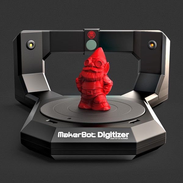
Will there be a tool that people can download?
Yes – we’re currently working on releasing one soon.
When?
I’m currently porting the software to the newest libraries (which
unfortunately means reimplementing lots of stuff from scratch) but in
a few months time we aim to release a linux-based demo which will
hopefully be followed by a windows based demo after that.
Art Contests Gadget Lab Gadgets Inspiration Software Tutorials What's Hot
Almost Everything You Wanted to Know About 3D Scanning from Direct Dimensions, Inc.
Almost Everything You Always Wanted to Know About 3D Scanning*
*(But Were Afraid To Ask)
Intro:
Every year, we meet many people who think what we do is interesting, but aren't quite sure how our 3D scanning technologies can help them. We're sure that if you clicked on the link to read this article, you might be one of those people. Dont worry, Direct Dimensions is here to help -- our easy to follow primer on 3D scanning will help you discover the ways our cutting-edge technologies can help you and/or your company.
Almost Everything You Always Wanted to Know About 3D Scanning* (*But Were Afraid to Ask) will cover the following topics in continuing installments in our monthly newsletter and also on our website. The topics with chapters indicated are completed and posted, the rest will follow so sign-up for our monthly newsletters for new chapters and check back on our website:
- Chapter 1: The Basics of 3D Scanning and Digital Modeling
- Chapter 2: Different Methods for Data Collection
- Chapter 3: Digital Modeling - Converting Raw Point Clouds into CAD Formats
- Chapter 4: Reverse Engineering - Design-Intent CAD Models
- Chapter 5: Inspection / Analysis - Comparison to CAD
- Chapter 6: Downstream Applications for 3D Data
- Chapter 7: Digital Model Formats - The Many Flavors of 3D CAD
- Chapter 8: Using 3D Data for Visualization
- Chapter 9: Rapid Prototyping - Making Physical Objects from Scan Data
- Chapter 10: The Future - Desktop Scanning and Manufacturing
- Chapter 1
- Ch 2
- Ch 3
- Ch 4
- Ch 5
- Ch 6
- Ch 7
- Ch 8
- Ch 9
- Ch 10
Chapter 10: The Future - Desktop Scanning and Manufacturing
Before we finish our series Everything you always wanted to know about 3D scanning we wanted to take a moment to talk about what we think is the immediate future in 3D scanning and manufacturing: the technology is going Desktop.
In the last few years, companies have been creating more products with smaller footprints, at much lower price points, making the technology a viable tool for schools and medium to small businesses. In addition to these new products, students and hobbyists have been creating (and sharing) do-it-yourself versions of 3D scanning and rapid manufacturing products. Soon we could see 3D scanners and printers in home offices!
Coming in the near future to a home workshop near you!
Commercial Desktop and Handheld Scanners:
There are a few digitizers and scanners out there that are sized and priced for the small business. The price points are not yet for your everyday consumer, but it is getting closer all of the time.
- One of our favorite desktop digitizer/scanners is the Microscribe. It is a miniature articulating arm that is easily portable, is compatible with most popular reverse engineering and metrology packages, and offers near metrology level accuracy in a small package.
 Obviously you are not going to digitize an airplane with this but we consider it the first major desktop digitizer (an attachable scanner is also available).
 - 3D metrology has also entered the realm of handheld and wireless. eMicroscibe also now offer the MobiGage, the first handheld 3D metrology app. You dont even need a computer, just a Microscribe and an iPhone or iPod Touch, to take measurements.
- Next Engine also offers a desk top 3D laser scanner. Its compact size, ease of use, customer support and price point are quickly making it a popular choice for small businesses and individuals.
Open Source, Consumer and Up-Coming Scanning Technologies:
While they dont come close to offering the same kind of accuracy as current available scanning systems, there is a burgeoning community of small businesses, hobbyists and students who are working to bring 3D scanners into the home. New products are rapidly developing.
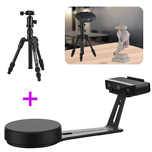
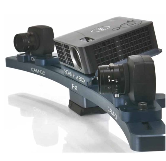
- Qi Pan, a student at Cambridge University has created ProFORMA, which uses a web cam to collect data and create a color 3D model.
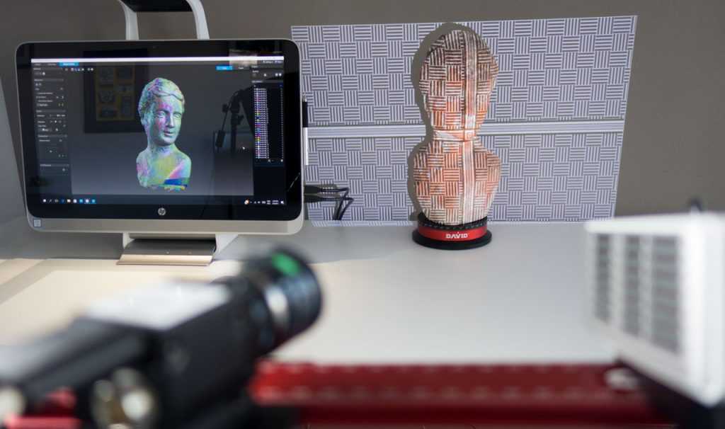
- David Laser Scanner offers a kit to build your own basic scanning system using every day objects like a web cam and hand held laser pointer.
- Perhaps the ultimate in DIY scanners, Friederich Kirschner used Legos, a webcam and some milk to create 3D models.
Desktop 3D Printers:
Like 3D scanners, 3D printers have already reached the small business market and are now just entering the individual consumer marketplace. Their build envelopes are limited but what could be cooler than printing your own action figures, robot parts, or 3D portraits?
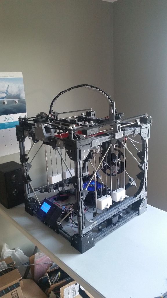
- The RepRap project is an open-source project aimed at creating self replication rapid manufacturing machines. Based out of Bath University, the project shares its plans and the RepRap community can build as is or make their own improvements, which they can then share.
- At the other end of the Desktop 3D printer spectrum comes the V Flash from 3D Systems. Rather than making your 3D printer from scratch you can buy this smaller version of traditional additive manufacturing technology.
 It is priced for small businesses and schools.
 - In the same market space as the V Flash, Solido bills their SolidPro300 as the world's most cost efficient and flexible 3D printer. In the US the SolidPro300 is distributed by Enser.
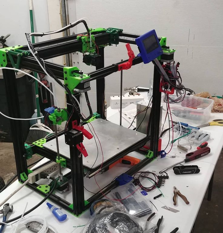
- Between RepRap, the V Flash, and SolidPro300 comes the Makerbot Cupcake CNC. Makerbot sells a kit for the Cupcake CNC but the customer puts it together. Like RepRap, they also host a community called Thingverse. Though their community revolves more around the 3D models than the machine itself. They are also working on a 3D scanning kit.
- HP has also recently announced that they are entering the market in an agreement with Stratysis who will produce mainstream 3D printers using Fused Deposition Modeling technology.
The above examples are just a small selection from a quickly developing marketplace, but they are a good indication of what home scanning technologies are just around the corner. Thanks for reading Everything you always wanted to know about 3D scanning, we hope it is has been an informative series!
If you have any questions feel free to contact us at info@dirdim. com.
com.
Stay tuned to our Newsletter each month. Next month we are introducing a new feature called Ask the Expert. You can submit questions about the 3D scanning and modeling process, or even how to deal with a specific problem you may be having to [email protected].
Chapter 9: From Digital to Physical Rapid Prototyping and Milling
Up to now weve been discussing putting physical objects into the realm of the digital, but before we finish this series we need to talk about another common application for our 3D scanning and modeling processes. Chapter Nine focuses on creating physical objects from digital data.
Important Terminology
Additive Manufacturing the process of making a physical object from 3D digital data by layering materials; also known as rapid prototyping and 3D printing.
Milling a subtractive process of removing material to create a physical object directly from 3D digital data by the cutting away from existing solid material.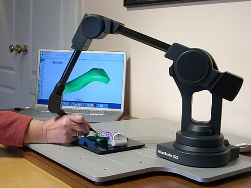
Applications
You may be asking, why do I need a physical replication of my digital model? After all, we just spent 8 months talking about turning your physical parts into various digital formats. But there are many good reasons to create new physical models of your data. Here are a few:
- Scaling: Making enlargements, reductions, or even exact size replicas...we can do it all. After a Digital Model has been created, there are few boundaries as to how big or how small we can replicate your object or part.
- Restoration: Our technology enables us to capture accurate 3D data that can be used for manufacturing to completely restore any object that has been damaged by weather, neglect, natural disasters, etc. such as historical monuments and artifacts or aged aircraft and automotive parts.
- Manufacturing Prototype: With a digital model, Direct Dimensions can create a physical prototype that can be used for testing or to manufacture final pieces, such as milling a foam sculpture for a bronze casting pattern or creating a finished prototype as a concept model for a new consumer product.
And now we can talk about the best ways to create the physical models.
Additive Manufacturing (AM)
There are a variety of additive manufacturing equipment manufacturers and processes on the market. Regardless of the type of AM, the various machines read the 3D data most typically in an STL file format. We discussed this format in earlier editions. The software within the machines then generates the layering instructions and directs the deposition of successive layers of material needed to build up the physical part. Essentially this part is created from cross sectional layers. The layers are fused together automatically and ultimately create the final shape, an exact physical replica of the 3D model. Additive manufacturing is an umbrella term that covers many of the following processes.
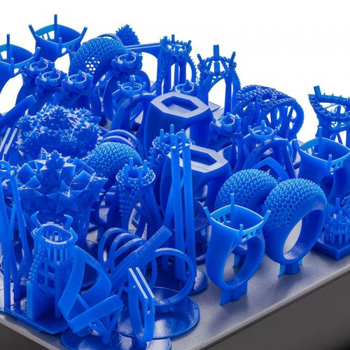
- One of the earliest and most common types of AM is called Stereolithography (also known as SLA). SLA builds pieces using a laser and a vat of UV-curable liquid resin.
 Each thin layer of resin is solidified and secured to the layer below with every pass of the UV laser. SLA is good for producing models, patterns, and prototypes. A downside to SLA is that it generally requires support structures to be included in the build, which is part of the SLA process.
 - Another AM process is Selective Laser Sintering (also known as SLS). Unlike SLA, SLS can utilize a wide variety of materials such as plastics, metals, and ceramics although post processing may be required. SLS does not require support material while building since it is built and incased within the raw material. SLS uses these materials in a powder format and, by fusing the powder together, creates the layers needed to build the part. SLS is increasingly being used to create final parts for when mass scale production isnt necessary.
- Similar to Stereolithography is Fused Deposition Modeling (also known as FDM). FDM, trademarked and marketed by Stratasys, also uses the additive platform build concept.
 Rather than raw liquid or powder, FDM uses thermoplastic materials which are applied through a heated nozzle that places a single thermoplastic bead at a time. These beads fuse together and harden as cooled. The plastics used in FDM are known for their strength and high heat resistance, making them good for product testing.
 - Perhaps the most similar to regular 2D printing is the concept of 3D Inkjet Printing. The only rapid prototyping technique that can print in multiple colors, 3D printing also uses a powder base material, but rather than sintering the powder, an inkjet releases a dot of adhesive mixed with coloring, allowing the layers to be built with colors. While the final model is not generally as strong as the other three techniques it is usually cheaper and faster and the colored prints allow for good representation of final concepts. Recently 3D printing has been used commercially to create personalized figurines from World of Warcraft and Rock Band avatar characters.

The primary advantage to additive fabrication is its ability to create almost any shape or geometric feature relatively quickly and inexpensively. We generally say that for a small part, you cant beat the price to complexity ratio. However the overall volume within a single build is generally limited for AM and for larger parts we recommend milling.
Milling
Milling is best described as a subtractive manufacturing technique. Most often used in the creation of metal production parts, tools, and molds for virtually any industry, an engineer, or even an artist, counts this as a well-tested valuable method. More advanced Computer Numerical Control (CNC) milling machines, like the various additive manufacturing machines, use a 3D CAD file to create a physical reproduction of the digital model. Unlike AM, CNC milling machines can utilize an extremely diverse range of materials including:
- Metals
- Stones
- Woods
- Waxes
- Plastics
- Even Glasses!
Milling steel or aluminum is a common option to make durable tooling. And stone and wood are common for sculpture and historical restoration projects.
Where is this all going?
We are almost done with our Almost Everything You Always Wanted to Know About 3D Scanning series. Dont be surprised if we add additional chapters now and then; the field is constantly changing and growing. We wrap up this series next month talking about the immediate future of these technologies, including desktop (or home) scanning and manufacturing.
Stay tuned for next months newsletter or click here to read previous chapters.
Chapter 8: Using 3D Data for Visualization
While we touched on visualization, one of several downstream applications in Chapter Six, the subject is so comprehensive that it deserves a chapter of its own.
As our lives become increasingly digital and interactive (via the web, video games, and even television and our cell phones), we have come to expect ever more realistic interpretations of real world objects within this virtual realm.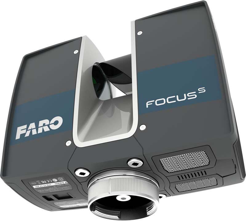 One of the best ways to perfect the digital form is to actually copy the shape of objects into 3D via laser scanning and digital imaging.
Visualization applications generally fall into the following categories:
- Animations - 3D digital movies made from computer models
- Renderings - 2D images made from computer models
- Direct 3Dviews - real-time interactive web-based 3D visualizations
- ShapeShot™ - real-time interactive web-based 3D facial images
Animations
When most people think of computer animation they think of the neat special effects in blockbuster movies and the animated explanations of complex events on the nightly news, such as train accidents. Yes - 3D models are frequently used for those types of animations. But often these animations are pure visualizations where the dimensional accuracy of the objects is less important as long as it looks good.
Our brand of 3D scanning and modeling is more valuable when the quality of the models is critical, such as for museum objects, or military simulations, or for animating highly recognizable objects for tv commercials such as cars.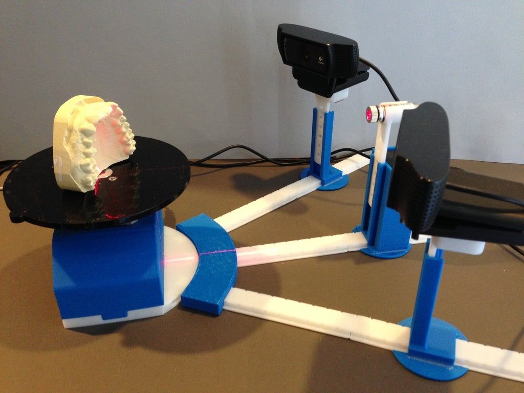 These situations require accuracy and authenticity, which scanning provides, so the objects in the animations look as real as possible. Often real colors and textures are captured and applied to provide that much more realism.
We have created numerous 3D animations from our 3D scanned models for a wide variety of applications including illustrating complex medical procedures, forensic analysis, describing historic preservation sites, and even for Hollywood movies and commercials.
Animation - Bringing Lincoln to Life
Animation - Realistic CG Microwave
Animation - Virtual Urban Environment
Renderings
Rendering is the process of creating a still image from a 3D model. High quality 2D renderings are often created from an existing 3D model that was originally captured for other purposes. These renderings can be used for graphical presentations, marketing, and even websites.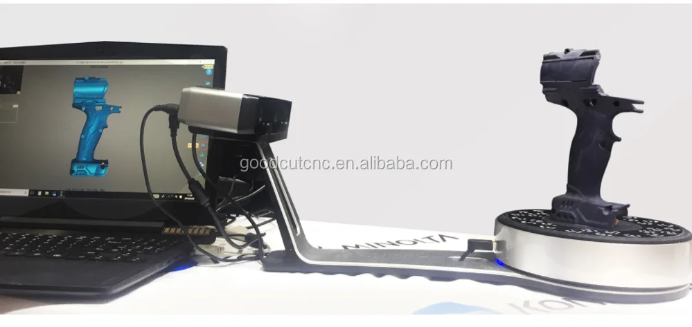 For instance, if a product designer has created a hand-carved physical model for reverse engineering purposes, he can also use that same digital file to create awesome 2D images of his product for marketing graphics. The great thing about a rendering created from a 3D model is that it is highly accurate and quick to render out multiple lighting and background states to create multiple renderings without staging new photography shoots.
Direct 3Dviews
A Direct 3Dview is a fully-interactive real-time 3D presentation of a digital model in a virtual environment. This 3D model visualization can be displayed via a website, a PowerPoint, or even in a stand-alone format. The Direct 3Dview of your object can be used to create an on-line 3D catalog to allow web visitors to fully experience the product - virtually. Another great application is for 3D proofs of concept for a new design or invention in a collaborative viewing environment.
Features of the Direct 3Dview include:
- Smallest viewer on the web - the one-time plug-in is only 130KB
- Smaller digital file sizes = faster download times
- Easily integrates into web sites
- Viewer supported in e-mail as well as PowerPoint
- View file in actual 3D, not a series of images
Direct 3Dview - Mattie Peace Garden
Direct 3Dview - French Medal
Direct 3Dview - Custom Game Character
ShapeShot™
ShapeShots™ are high resolution 3D snapshots of faces that are incredibly life-like.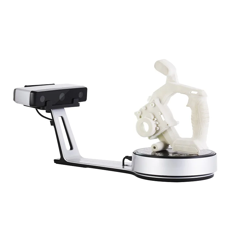 ShapeShot™ enables online personal interaction with amazingly real 3D avatars of you, friends, and family for social networking, online gaming, virtual collaborative environments, and fabrication of personalized consumer products.
New advances in 3D imaging technology have made it to possible to capture faces in a split second and receive an interactive 3D model within minutes with almost no effort.
Direct Dimensions is currently developing the ShapeShot™ concept. See www.shapeshot.com for more information.
ShapeShot™ - Video Game Avatars
ShapeShot™ - New Applications Daily!
ShapeShot™ - Harry
From the Virtual to the Physical
The above examples are just a drop in the bucket when it comes to visualization applications. But what happens if you want to take your 3D model and make a physical copy of it? For instance, can you take your Guitar Hero avatar and get a physical 3D copy made? You can, and that process is called Rapid Prototyping or RP. Rapid Prototyping is just one of many technologies that fall into the 3D Printing category and well be talking about that next.
Stay tuned for next months newsletter or click here to read previous chapters.
Chapter 7: Digital Model Formats - The Many Flavors of 3D CAD
Were going to take a little pause here for a mini chapter. Weve talked about the many things you can do with a CAD model but that can lead to some questions. How can I use an OBJ file and how is it different from an STL? Can an IGES and a STEP file essentially be used for the same thing?
These are what we call the Flavors of CAD and were here to provide you with a short list to help clear up some details.
The Various CAD Flavors:
- ASCII (or ASC) an X,Y,Z point cloud file in ascii text format.
- DWG - This is a native AutoCad drawing file
- DXF Drawing Interchange File - a neutral version of a DWG file
- IGES Initial Graphics Exchange Specification - a neutral format for exchanging CAD data between many different software programs
- OBJ an open data format that represents the vertices of polygons
- PRT a native CAD format for Pro/ENGINEER and NX (Unigraphics)
- SLDPRT a native CAD format for SolidWorks
- STEP "Standard for the Exchange of Product model data," (ISO 10303) an advanced neutral format for exchanging CAD data between many different software programs.

- STL Standard Tessellation Language - a polygonal model format similar to OBJ and several others
- WRL (VRML) Virtual Reality Modeling Language, a polygonal file similar to OBJ, STL and several others and can include color
- X_T - a semi-neutral CAD format
Wikipedia maintains an extensive list of CAD file formats that might be of further interest at: List of File Formats - Computer-aided design (CAD)
Neutral Formats:
From the list above youll notice that some CAD formats are considered neutral, specifically IGES and STEP formats. These two formats were specifically created to neutrally exchange 3D CAD data across different CAD packages.
IGES was created in 1979 by a group of users (including Boeing and GE) with support from the Department of Defense (DoD) and NIST to exchange data more easily. Since the late 80s the DoD has required that all Digital Project Manufacturing Data (PMI) be deliverable in IGES format.
STEP is an ISO standard released in 1994 to be the successor to IGES.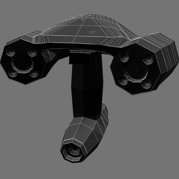 While widely used it has never totally replaced the IGES format.
Extra Flavors:
While the above examples are standard across CAD packages, many industries, such as Architecture and 3D modeling for computer graphics have their own packages and files types. We like to think of these as extra flavors, like CAD dessert.
3D Graphics 3D graphics formats are generally proprietary according to package. Some popular graphics programs are, 3D Studio Max, Maya and Lightwave. Popular gaming companies such as Blizzard Entertainment and other film studios often develop their own in-house formats. However, many consumer 3D graphics packages can import OBJ files.
3D Modeling for Architecture A new style of modeling for facilities, such as buildings and processing plants, is developing rapidly. This new CAD software contains a relational database component to store metadata for the design entities, such as the style and make of windows or doors, or the schedule of the I-beams and piping.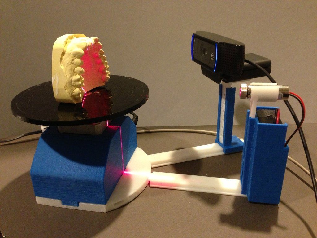 This new class of software is termed BIM for Building Information Modeling and is working to combine facilities management into the database concept as well.
The above examples are just a small taste when it comes to the flavors of CAD, but they are the most common files used. Hopefully this little list has helped a bit. If you have any questions you should just ask your 3D service provider and they will be happy to help. You can always ask us questions at [email protected].
Stay tuned to our Newsletter each month for more chapters. If you cant wait until next month, then feel free to visit our Learn More Page.
Chapter 6: Downstream Applications for 3D Data
Weve reached the fun part! What can you do with a 3D model? Practically anything!
In a world that is increasingly digital, most industries now utilize 3D files in some fashion. Were seeing them show up in many different places lately.
At this point in the process, you have your 3D model from your scanned original part. It has been either digitally modeled into a polygon format or reverse engineered into a CAD format, according to your needs. But, you can do so many things with your 3D data things you might not have even thought of yet! Chapter Six covers the different downstream applications for 3D data file.
Downstream applications generally fall into the followings categories:
- Documentation/Archival
- Re-Engineering/Design
- Inspection/Analysis
- Replication/Reproduction
- Visualization/Animation
- Various Industry-specific Applications
Documentation/Archival
After your part or object has been laser scanned and modeled you now have a digital "backup" of the object. Scan data for archival purposes is useful for a number of industries: Aerospace/Defense, Consumer Products/Industrial Design, Architecture/Historic preservation and Museum/Fine Art. At Direct Dimensions weve scanned many objects specifically for the purpose of creating a digital document.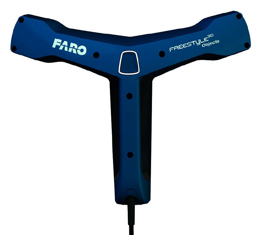 Archival scans have ranged from the Lincoln Memorial (post-9/11) to a huge rare meteorite to legacy aircraft parts that are no longer made.
This digital model will:
- Protect you from accidental part loss, almost like an insurance policy
- Provide you with a working "virtual" blueprint in order to rebuild, recreate, or remanufacture
- Give you the ability to start from a base model and create something new without having to start from scratch
Re-Engineering/Design
While Reverse Engineering as a process was covered in Chapter 4, it is also an application that is particularly useful in the Aerospace/Defense and Industrial Design industries. With a Reverse Engineered model you can make engineering and design changes of your part or object in a variety of ways or use it for specific types of analysis:
- Add or subtract design features to the existing part or object
- Use as a base model to design a new part or object
- Use model for FEA and similar analyses
Inspection/Analysis
Also covered as type of process, inspections are a great use for 3D data particularly for any types of manufacturing.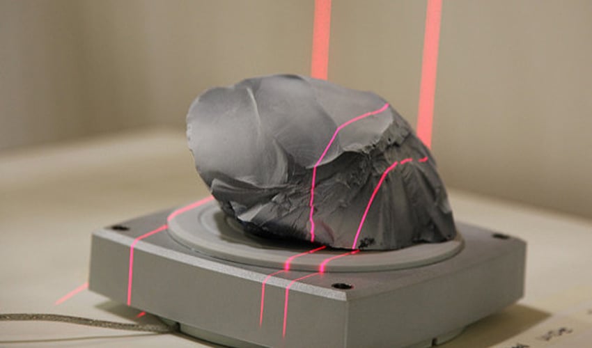 Using our advanced laser scanning and reverse engineering tools and processes, Direct Dimensions can inspect and analyze your part or object in a variety of ways:
- Compare a scanned part/object to a "nominal" or intended design model
- Compare a scanned part/object to 2D drawing dimensions
- Compare a scanned part/object to another scanned part/object
Replication/Reproduction
While this will be covered in depth at a later time, Replication is one of the earliest and still most important uses for a 3D file. Using either 3D printing or milling processes, your digital file can be created as a physical part. After you have laser scanned or reverse engineered your part, there are virtually limitless options for replicating that object. Replication can be used for:
- Scaling in either direction
- Restoration
- Manufacturing Prototypes
- Making Products
Visualization/Animation
This application definitely falls into the realm of advertising and entertainment but also museum presentations, legal cases, and even high quality training simulations are also all great uses for 3D model visualizations and animations.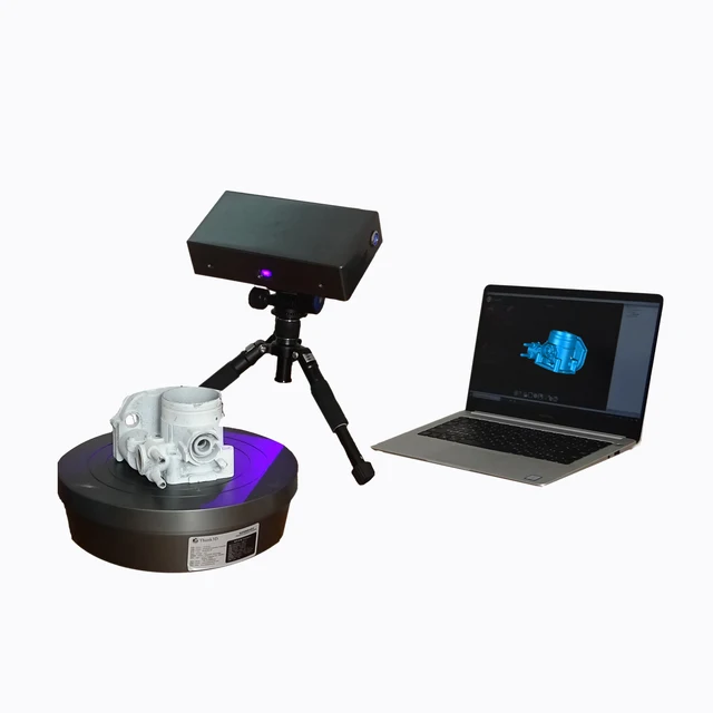
- Direct 3Dview of your object can be used to create an on-line 3D catalog or proof of concept.
- FaceScan scanning a person for animations, avatars, mass personalization of consumer products, or even simulation programs.
- Animation recent scans of people, objects, and structures have been used to create commercials, films, music videos, and video games.
- Rendering high quality 2D renderings using 3D models can be used for marketing purposes. Renderings of structures and viewpoints have also been used in legal cases to prove/disprove eyewitness accounts.
Video - Realistic CG Microwave
FaceScan - Mike R.
Direct 3Dview - Custom Game Character
Industry-specific Applications
While many types of industries can utilize the previously listed applications, there are a few 3D model apps that are very specific, but we feel we should list:
- Architecture/Construction: scanning facilities for BIM databases and creating traditional blueprint drawings
- Museum Research/Fine Art: investigative scanning for provenance and comparative research
- Virtual 3D Worlds: 3D scanning facilities, objects, and people specifically for use in virtual worlds and social networks, such as Second Life
Same 3D Data, Many Different Uses: Repurpose!
Often, with just a little bit of extra work, you can create different, valuable deliverables with the same basic scan data or 3D model.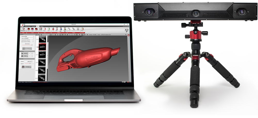 Some examples are:
- A consumer products company has an object scanned so that it can be prototyped. What they might not know is that with a little tweaking of the model they can also gather the measurements needed to create perfectly fitting packaging and also creating photorealistic models for subsequent advertising or a virtual catalogue.
- An aerospace company has a cockpit scanned for human factors analysis. If enough data was initially collected, that same data could be used to help create training simulations.
- A major museum has a sculpture in its collection that is rapidly deteriorating and they want to scan it for documentation. That data could be used to create high quality mini replications to be sold in the gift shop or for research (possibly comparing it to similar castings by the same artist).
The Sky is the Limit!
The above examples are just a drop in the bucket when it comes to uses for 3D models. If you have a possible application that you think a 3D model would work for, you should just ask your 3D service provider if it can or has been done. If they are anything like us, they will either have already done it (or tried it) or be so intrigued by your application that they are willing to give it a shot! And if you cant do it yet, check back often; new applications and methods are being invented every day.
The world of 3D imaging, modeling, and engineering continues to grow at such an incredible rate that older applications are always being improved upon and new ones are always being dreamed up.
Stay tuned for next months newsletter or click here to read previous chapters.
Chapter 5: Inspection/Analysis - Comparison to CAD
We are almost ready to move on to downstream applications for 3D models, but before we jump into that, we need to talk about one more application for scan data. Chapter Five will cover how this data can be utilized for quality inspection.
Important Terminology
CMM - Coordinate Measuring Machine, a mechanical device that obtains 3D coordinates by probing, may be either touch probe based or non-contact, portable or stationary, or motorized or manual.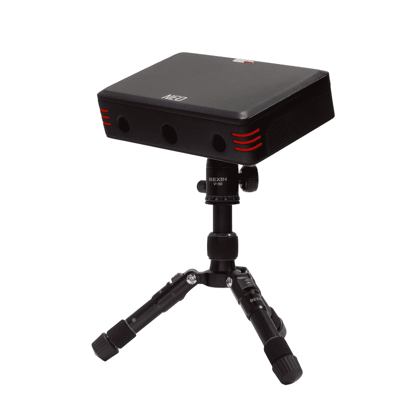
Laser Tracker - sends a laser beam to locate a reflective target held against the object to be measured. The beam reflects back to the tracker and calculates the distance and angle of the targets location. Laser trackers are a great option when you need extreme accuracy over larger measurement ranges.
Color Map - a graphical display for visualizing dimensional differences between the measured shape of an object and its nominal CAD model; deviations are mapped to a color spectrum indicating location and magnitude. A reference key maps the deviations to values.
A History Lesson
While we think of the 3D scanning industry as something very new, the first 3D digitizers, Coordinate Measuring Machines (CMMs), were actually built in the 1960s and the entire purpose of this development was to perform dimensional inspections. Fifty years later, inspections are still one of the most common uses for 3D digitizing and scanning systems.
In the late 1980s engineers at the then-Martin Marietta (including Direct Dimensions founder and president Michael Raphael) became aware of a company making articulating arms for medical measurements and they began working with the company (Faro Technologies) to develop a portable CMM for inspections in the aerospace industry. After the creation of the portable CMM, the options for 3D measurement and inspection exploded. Laser Scanners were added to the portable arms and then Laser Trackers were developed.
Twenty-five years later, portable scan arms are common measurement solution in major manufacturing firms across the world and in industries ranging from aerospace to automotive and power generation to medical.
Types of Inspections
There are many different types of inspections that can be done utilizing 3D technologies:
- One of the fastest and most informative types of inspections is the Dimensional Deviation, CAD to Part Inspection.
 A typical process for a Scan Arm, the scan data is compared to the original CAD model in a software package which will then show deviations by a color map.
 - A variation of the Dimensional Deviation is the Virtual Assembly Analysis. By using reference points, such as interface datums, we have the capability to, in a virtual environment, simulate and identify how parts will fit together in their real-world assembly. We can do this by using assembly characteristics of the part (such as weld points, slots, and holes) to apply the mating constraints during assembly. This is also known as a reference point fit which can discreetly control part movement in any axis of each control point. The analysis can show part collision or spacing in a real world scenario done virtual.
- Parts can also be measured while they are in the process of being machined, an On-Machine Inspection allows for important characteristics to be measured and changes to be made while the piece or tool is still being created.
 These are typically done with either a Portable CMM with probe and scanner, or a laser tracker depending on the size of the object being machined.
 - Similar to on-machine inspections, are real time inspections for Installation Alignment. This is helpful for installations of major equipment and is typically done with a laser tracker, PCMM, or similar.
- Perhaps the most comprehensive of the inspections is the First Article Inspection (FAI) which involves a thorough point to point inspection of a physical part against the production drawing dimensions. This is a very typical process for a portable CMM.
Getting Started
In the previous chapters, to get you going, we discussed the software products that we use literally every day here at Direct Dimensions. Below are the products that take the 3D measured data from the portable arms and scanners and perform the inspection analysis processes.
Each of them has some capabilities to perform the two main types of inspection discreet point dimensional inspection and dense point cloud comparison analysis.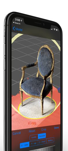 Some have more comprehensive capabilities that include GD&T or special case analyses; and some specialize in certain areas such as ease of use or multi-scanner integration more than others.
At Direct Dimensions, we use all of these regularly and help our customer understand the strengths of each package relative to their specific application and company needs. If we are performing the project for someone as a service, they get the satisfaction of knowing we will use the best software for their inspection. Feel free to call us directly for more specifics on how these packages compare for your needs.
- CAM 2 Measure X (by Faro)
- Geomagic Qualify
- InnovMetric PolyWorks Inspector
- Rapidform XOV
- Verisurf
Now what can I do with my model?
Having learned what you can do with your data: inspect, reverse engineer or digitally model, we are now ready for the fun part! Chapter 6 will be an overview of the downstream applications for 3D models. The possibilities are numerous and we and our customers are thinking of new ideas every day.
Stay tuned to our Newsletter each month for more chapters. If you cant wait until next month, then feel free to visit our Learn More Page.
Chapter 4: Reverse Engineering
Converting Raw Point Clouds into CAD Formats: Step 2 Files that can be brought into Parametric Modelers
Youve read our overviews, figured out how to collect data, and now that you have this data, what do you do with it? Chapters Three through Five will cover how this data can be processed into more useable digital forms.
In Chapter 3 we discussed processing 3D data into polygonal models and dumb solids, but what happens when you need more than a simple mesh file or you must have geometry features to enable your redesign process? As previously discussed, we categorize the processing of the collected data into two main categories: Digital Modeling and Reverse Engineering.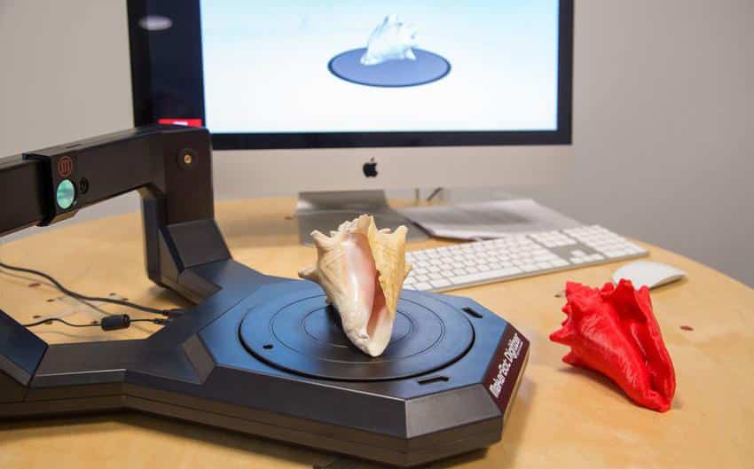 In Chapter 3 we discussed Digital Modeling (polygonal or rapid NURBS dumb solids), but when you need to go beyond these simpler model formats, we call that Reverse Engineering with design intent.
Reverse Engineering - the process of measuring and then creating a CAD model of an object that reflects how the object was originally designed (with its design intent).
Design Intent - the intended design of an as-built physical object. Every manufactured part or object varies from its original intended design by some factor. These imperfections can be identified, analyzed, and corrected during the reverse engineering process.
As-built - modeling which captures the exact physical shape of an object as it actually is, with its imperfections (as opposed to its design intent).
When should I request a Parametric Model vs. the simpler Rapid NURBS or Polygonal Mesh Model?
So when does a project fall into the category of Reverse Engineering as opposed to Digital Modeling? Why should I opt for Reverse Engineering when it sounds more time consuming and requires additional processing, and therefore is probably more expensive?
At Direct Dimensions our recommendation generally depends on several factors including: shape (organic vs. geometric) and desired file output. If you want to make a Rapid Prototype of a hand-carved chair seat then going the digital modeling route is probably a fine option for you. If you want to scan an airplane to create an accurate model for CFD analysis, need a model of an impeller for flow analysis, or require a model of an engine casing for a redesign then youll probably want to spend the time and effort required creating a fully reversed engineered model.
Perhaps the biggest difference between Digital Modeling and Reverse Engineering is the desired file output. People that choose Digital Modeling generally will use the file for Rapid Prototyping or visualization purposes. When you need more than that, either for redesign purposes or for importing models into analysis programs, you generally choose to Reverse Engineer, which means bringing your files into parametric modeling software. There are essentially four types of models that work for this (two of them we discussed in the previous chapter):
- A Rapid NURBS dumb solid (previously discussed in Chapter 3) starts with the polygonal model.
 NURBS surfaces are wrapped over the polygonal mesh. This wrapped surface model is smoother than a polygonal model and generally contains no regular geometric features. This type of NURBS model can be brought into parametric modelers such as SolidWorks (albeit with no parametric history which is why we call it dumb).
 - The bridge between Digital Modeling and Reverse Engineering is the Hybrid Model (previously discussed in Chapter 3). A hybrid model is a polygonal model that has been converted in a rapid NURBS surface model and then also uses some traditional solid modeling techniques. It is commonly used when basic geometric features, such as holes & edges, blend with complex organic contours, such as a machined casting.
- The Hybrid dumb solid model is considered a step up from the fully Rapid NURBS, in both time and effort, but certainly not as time consuming as a fully reverse engineered parametric model. Unlike the Rapid NURBS, which is essentially a wrap around a polygonal frame, the hybrid dumb solid contains some geometric features such as holes, planes, and radii but these features still have no parametric history.
- A fully reverse engineered Parametric Model will have a fully functioning feature tree, allowing for complete redesign if necessary. These models are built as if they were engineered from scratch, making them perfect for the reverse engineering of legacy parts and redesigns.
Design Intent or As-Built?
When choosing to reverse engineer a part, it is important to decide if the part should be reverse engineered as-built (or as-scanned, in its current state) or engineered with its design intent. Often the actual physical production parts are off just fractions of millimeters or sometimes the parts have worn down a bit from the original fabrication. It is important to clarify the end use of the data when discussing your project with a reverse engineering firm so they know whether you need design intent or as-built models.
The Reverse Engineering Advantage
There can be a fine line between Digital Modeling and Reverse Engineering and sometimes both methods can be a valid solution to 3D problems.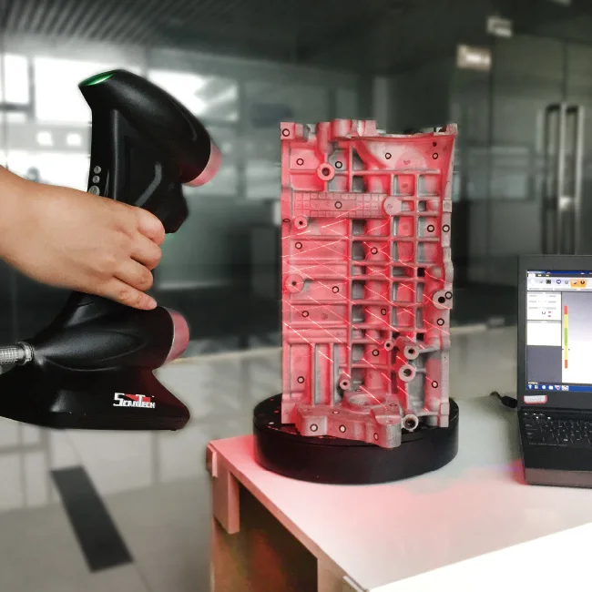 Some advantages of Reverse Engineering are:
- Can be brought into Parametric Modeling Packages (solid modeling CAD software)
- Parametric Models will have a feature tree that is editable
- Other than Rapid NURBS dumb solids, reverse engineered models contain geometric features such as planes and radii making the models a better fit for designing and measuring.
- Reverse engineered models are great for analysis software such as for CFD and FEA.
Getting Started
In the previous chapters, to get you going, we discussed the software products that we use literally every day here at Direct Dimensions (shown in alphabetical order):
- Geomagic
- Imageware
- Innovmetric PolyWorks
- Rapidform
The CAD packages we use frequently include: AutoCAD, CATIA, Siemens NX, ProEngineer, Rhino3D, and SolidWorks.
What else can I do with a model?
Now that you know a bit more about what we call Digital Modeling and Reverse Engineering you may feel like you dont need to know anything else about the uses and creation of 3D models. However, there is one more major use of 3D scanning that we want to talk about. The next chapter will discuss utilizing 3D Scanning for Inspection / Analysis.
Stay tuned to our Newsletter each month for more chapters. If you cant wait until next month, then feel free to visit our Learn More Page.
Chapter 3: Digital Modeling
Converting Raw Point Clouds into CAD Formats
Youve read your overview, figured out how to collect data, and now that you have this data, what do you do with it? Chapters Three through Five will cover how this data can be processed.
As you learned in Chapter Two, Direct Dimensions breaks data collection into two common methods: Laser Scanning and Digitizing. We also categorize the processing of the collected data into two main categories: Digital Modeling and Reverse Engineering. In this chapter, well tell you what you need to know about Digital Modeling.
Digital Modeling: the process of creating a computer model of an object that exactly replicates the form of the object.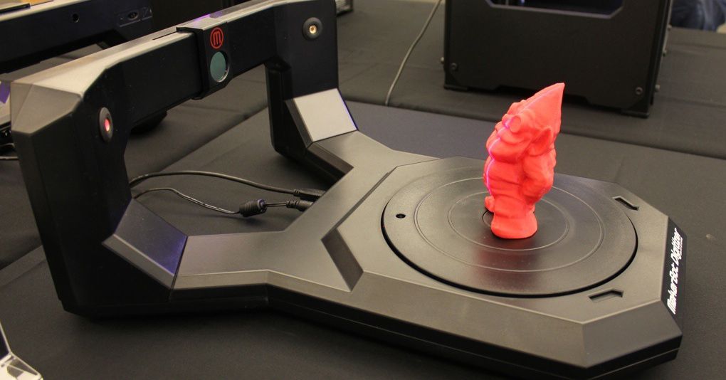 Laser scanners are used to capture the 3D data of the object, and this data is transferred to the computer where it is aligned, edited and finalized as a complete 3D model.
Polygonal Models and Dumb Solids
So, when does something fall into the category of Digital Modeling as opposed to Reverse Engineering? At DDI it generally depends on a couple of factors: shape (organic vs. geometric) and desired file output. As a general rule of thumb, organic shapes tend to fall into the Digital Modeling category, as do polygonal models (STL Files) and Rapid NURBS Dumb Solids.
A Polygonal Model is a faceted (or tessellated) model consisting of many triangles. Facets are formed by connecting points within the point cloud. STL files can be used for visualization, rapid prototyping, design, milling, and analysis software.
A Rapid NURBS Dumb Solid (usually in IGS format) starts with the polygonal model. NURBS surfaces are wrapped over the polygonal wire frame.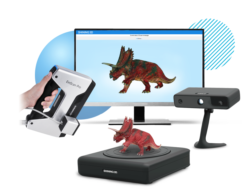 This wrapped surface model is smoother than a polygonal model. The NURBS model can be brought into parametric modelers such as SolidWorks (albeit with no parametric history which is why we call it dumb).
The bridge between Digital Modeling and Reverse Engineering is the Hybrid Model. A Hybrid model is a polygonal model that has been converted in a rapid NURBS surface model and then also uses traditional solid modeling techniques. It is commonly used when basic geometric features, such as holes & edges, blend with complex organic contours, such as a machined casting.
Do Reverse Engineering and Digital Modeling ever Overlap?
In addition to Hybrid Models, there are instances when it is appropriate to use both Digital Modeling and Reverse Engineering techniques. For example, when collecting data of a large object (such as a plane) for Reverse Engineering, it is necessary to use a laser scanner to capture the massive amounts of surface data. The data output from a laser scanner is a point cloud, but point clouds cannot be brought into any CAD packages. Before the data can be transferred into CAD it must be digitally modeled into either a polygonal model or a Rapid NURBS dumb solid.
The Digital Modeling Advantage
There can be a fine line between Digital Modeling and Reverse Engineering and sometimes both methods can be a valid solution to 3D problems. Some advantages of Digital Modeling are:
- Digital Modeling generally offers a faster and more cost effective solution.
- It presents a great solution for creating solid models when an object has organic contours.
- Offers excellent dimensional accuracy and can be utilized for comparative analysis.
- While it is true that Rapid NURBS Dumb Solid models do not have parametric history, they can be utilized as a base for design work and Boolean functions are possible.
- Unlike raw point clouds, Digital Models can be visualized in rendering software as a solid object, which is great for seeing the overall shape and contour of the model.
Getting Started
In Chapter Two we discussed data collection and various brands of scanners and digitizers that we use on a daily basis.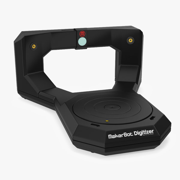 Dont worry! We wont leave you hanging on what software packages we recommend for digital modeling. We use the following packages every day at DDI (in alphabetical order):
- Geomagic Shape Studio: Polygonal and NURBS modeling and point cloud to CAD comparison. Geomagic can automatically generate an accurate digital model from any physical part.
- PolyWorks Modeler: Polygonal modeling and point cloud to CAD comparison. PolyWorks can process large point clouds over 100 million points and easily integrates with all standard digitizers and articulating arms.
- Rapidform: Third generation point processing software for creating native parametric "design-intent" CAD models directly from scan data. At Direct Dimensions we often use Rapidform in Hybrid Modeling but it also has a great Rapid NURBS function.
Tackling Reverse Engineering
Now that you know a bit more about what we call Digital Modeling and why it can be a great option, you are ready to tackle Reverse Engineering.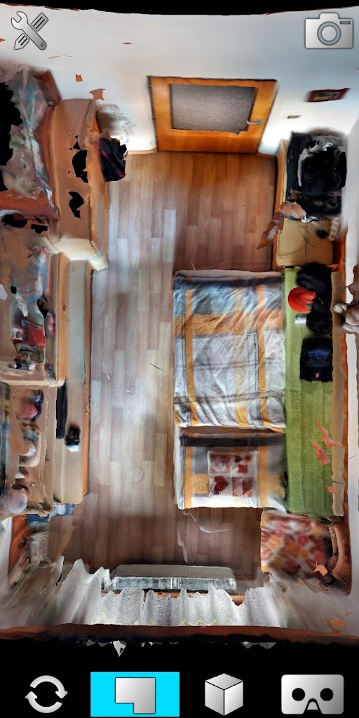
Stay tuned to our Newsletter each month for more chapters. If you cant wait until next month, then feel free to visit our Learn More Page.
Chapter 2: Data Collection
Now that you have a basic idea about how 3D scanning and modeling works, lets really get started. Before you can have a 3D model, you must have 3D data to create that model. Lets start there
So, what are the ways that 3D data can be collected?
There are multiple ways to collect 3D data but two of the most common methods (and the two most frequently used by Direct Dimensions) are laser scanning and digitizing.
During laser scanning, a laser line is passed over the surface of an object in order to record three-dimensional information. The surface data is captured by a camera sensor mounted in the laser scanner which records accurate dense 3D points in space, allowing for very accurate data without ever touching the object.
Laser scanners can be broken down further into types such as laser line, patch, and spherical.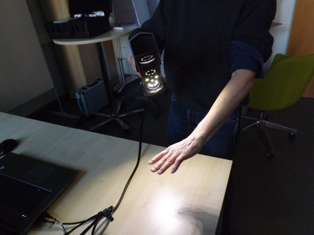 The FARO ScanArm, the FARO LS, the Surphaser, Konica Minolta Vivid 9i and Range 7 are some examples of laser scanners that we often use at Direct Dimensions.
The second major method is digitizing, which is a contact based form of 3D data collection. This is generally done by touching a probe to various points on the surface of the object to record 3D information. Using a point or ball probe allows the user to collect individual 3D data points of an object in space rather than large swathes of points at a time, like laser scanning. This method of data collection is generally more accurate for defining the geometric form of an object rather than organic freeform shapes. Digitizing is especially useful for industrial reverse engineering applications when precision is the most important factor. Stationary CMMs (coordinate measurement machine), portable CMM arms, and the FARO Laser Tracker are all examples of digitizers that we often use at Direct Dimensions.
Other methods of collecting 3D data include white light scanning, CT scanning and photo image based systems. These technologies are being utilized more frequently in the field of 3D scanning and new applications are being discovered every day.
To be digitized or laser scanned?
A general rule is that scanning is better for organic shapes and digitizing is most accurate for geometric shapes. In general, laser scanning is also used for higher-volume work (larger objects like cars, planes, and buildings). Laser scanning is also a great option for people who need 3D data of an object but would prefer that the object not be touched, such as for documentation of important artifacts.
Digitizing is often used for our engineering projects and first article inspections, in instances where precise measurements are required for geometrically-shaped subjects. This includes objects that have defined lines and planes and curved shapes, like spheres and cylinders.
This doesnt mean that you can never laser scan a part with many geometric features or that you cant digitize a plane (an entire plane can be digitized, believe us - weve done it!) or even a sculpture. These are just rules of thumb.
Utilizing multiple methods of Data Collection
There are projects when it is more cost and time effective to use multiple methods of data collection. A good example is a cast part with geometric machined features. You might need a 3D model of the entire part but really need incredible accuracy on the machined features while the freeform cast surface itself is not as important. In such a case it can be much more effective to laser scan the entire part and then digitize the geometric features. The data can be combined during the modeling phase (more on that in the following chapters).
Additional Scanning Information
Because you are trying to collect the most accurate data possible, there are a few more things to keep in mind before you run out and start scanning everything in sight.
- Bright light sources in the area, including the sun, can really mess up your scan data. At Direct Dimensions, if we are laser scanning an object outdoors we prefer to do it at night if able.
 Light can reflect off of your scanning object and create noisy data. This brings us to:
 - Very reflective materials generally do not scan well. This can be avoided with a light coating of white powder spray (or anything that dulls the reflectivity). There are also some scanner manufacturers who are actively working to solve this problem.
- Fixturing: whether you are laser scanning or digitizing, it important that your scan object will not move while you are collecting data. The tiniest motion will cause inaccurate data.
- If you need hard to reach/impossible to see internal data, you should consider CT scanning or destructive slicing, both can be great ways to augment your data. (more on those later).
Moving on to 3D modeling
Now that you have a good idea of what you need to collect data, you are ready to learn all about the various ways the data can be modeled. Chapters three through five will cover, 3D Modeling, Reverse Engineering, and Inspection Analysis.![]()
Stay tuned to our Newsletter each month for more chapters. If you cant wait until next month, then feel free to visit our Learn More Page.
Chapter 1: The Basics
What is a 3D model and how do you get it?
A 3D model is a digital representation of a physical object. If you already have an object, and you want it in a digital form, thats what we do. Direct Dimensions takes physical objects that you send to us and we use advanced 3D scanning equipment to capture and transform them into 3D digital models.
We do this by processing the raw data gathered during a 3D scan into a digital model that can then be used by you for many purposes. In the next chapter, we'll cover the different methods for collecting this data, including laser scanning and digitizing. A 3D model is incredibly versatile.
Why do I need a 3D model?
3D models can be used for many purposes like making an animation or visualization. They can be used to make design changes to make a new product. They can be used to perform dimensional and comparative analysis of an object, or even FEA and CFD analysis. They can be used for archival purposes - to accurately record the state or form of an object. They can be used to digitally repair damage that has been done to an object which can then reproduce that object in its proper form using rapid prototyping and milling technologies. They can even record your face in intricate detail! (And yes, some of our lasers are eye-safe!). There are no limits as to what can be done once something has been captured in 3D.
In short, our technologies allow almost any physical object to be recreated into a 3D digital format that can be used for just about anything you want.
When? Where? How Large? What are the limitations?
With our various technologies, we can capture objects indoors or outdoors, during the day or at night. The sky is the limit for how large and we also have technology that can capture even the smallest objects. Some of our equipment is portable so we can come to your facility, or you are encouraged to ship your items to our lab.
On the large side, Direct Dimensions has successfully scanned entire airplanes, historic monuments, ships and subs, tracts of land, and large interior spaces like buildings. Weve scanned mid-size objects like spacesuits, countless consumer products and art work. We've also done tiny, finely-detailed items like coins, medical devices, and dental appliances. We've even captured fingerprints and skin textures! The bottom line is that whatever your object, the tools exist to scan it, and its likely we use them.
What's next?
Now that you know the basics of what can be scanned and how 3D data can be used, you are ready to learn more about the different methods we use for data collection!
Stay tuned to our Newsletter each month for more chapters. If you cant wait until next month, then feel free to visit our Learn More Page.
Scanform - professional handheld 3D scanners
Our clients
See all3
Well Technology Company
Manufacture of industrial ventilation equipment
Well Technology
FENDERIST — Vladivostok
Development and production of tuning components
fenderist. com
com
BoatService – Croatia
Boatservice Group - A network of yacht service workshops operating in Croatia, Slovenia and Montenegro since 2008. Perform almost…
boatservice.eu
Bratuhin Customs - Izhevsk
Production of individual motorcycles and components: 3d scanning, reverse engineering, production and installation of side trailers…
bratukhincustom.com
Physics Racing - St.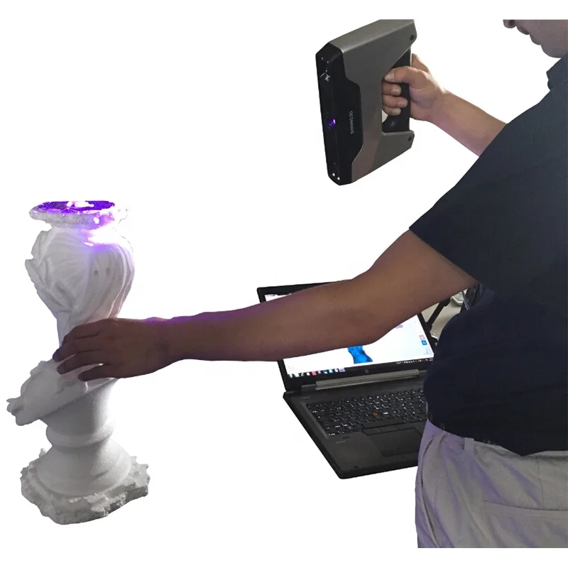 Petersburg
Quality construction, repair and maintenance of sports cars. Professional approach to work, preparation for exhibitions and competitions…
fizikaracing.vsite.biz
RMM manufacturing — Novosibirsk
Manufacture of downpipes and exhaust systems for Mercedes, BMW, Porsche, Audi, Aston Martin, McLaren, etc.
CAD Engineer
Affordable 3D scanning and CAD design services in Florida, US
facebook.com
KMZ - St. Petersburg
Kingisepp Engineering Plant - a domestic manufacturer of diesel, heat exchange and deck equipment
kmz1.ru
DirTire - Vladivostok
Manufacturing, engine swaps, design, CNC laser cutting, welding, custom work, 3d scanning, 3d printing.
4
"Sport brake systems" - JBT
CTC (Sports Brake Systems) is an official dealer of high-tech brake systems JBT, providing significant .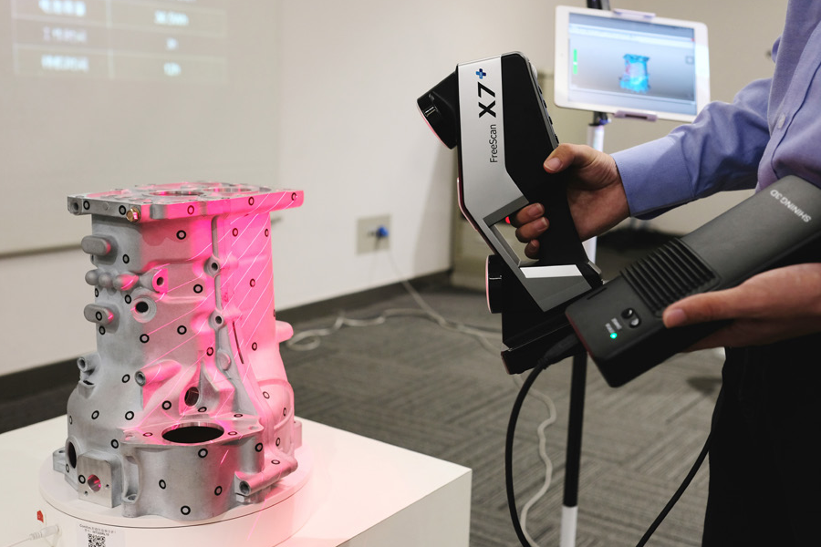 ..
..
View photo report
4
LLC "TAURUS" - Istra
LLC "Taurus" provides services for clearing land from unwanted trees and shrubs using mulchers.
See photo report
mulcher-taurus.ru
3
Steffi Group - Rostov-on-Don
The company specializes in laser cutting, marking, CNC metal processing, CNC tube and bar bending. 3D modeling, scanning…
View photo report
cnc-services.ru
14
SWAP POINT
The company specializes in engine swaps and car modifications. As the guys say about themselves: “We swap everything that moves, and what ..
See photo report
youtube.com/Swap
5
SVS-Sochi
Russian company for the development and production of tuning components for cars of any class with its own unique design.
See photo report
5
Magic Print
3D printing, 3D scanning, design and modeling in Chechnya
View photo report
6
3D-Cartel — St. Petersburg
3D-Cartel offer a range of services for: 3D scanning, 3D printing, Modeling, Reverse engineering, wax casting and aluminum casting
View photo report
6
Box 3D - Moscow
Specializes in 3D printing: large-scale objects, engineering composites, 3D scanning, modeling, design
See photo report
box3d.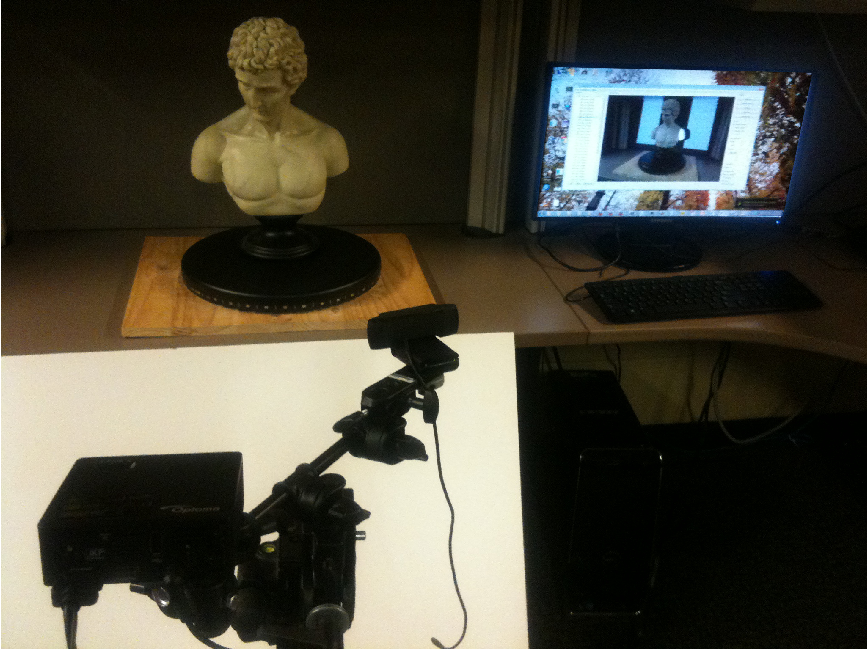 ru
ru
4
Auto Concept Studio – Car Audio and Tuning Studio – Ekaterinburg
Installation and adjustment of sound, production of podiums, etc.
See photo report
autocs.ru
VKontakte
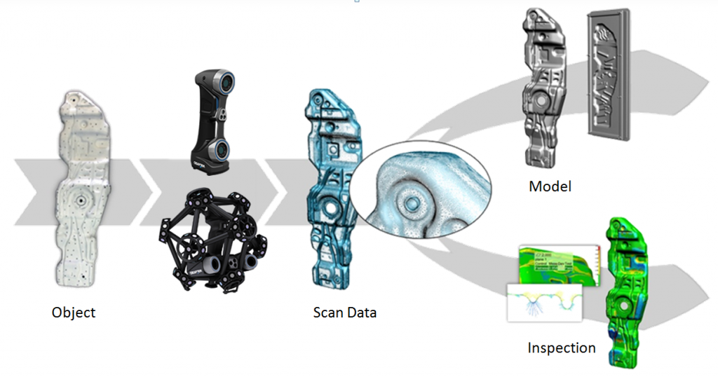
Application of 3D scanning and 3D printing in reverse engineering
Reverse engineering is a way of creating digital models from physical ones. Together with 3D scanning and 3D printing, it is an effective tool for prototyping.
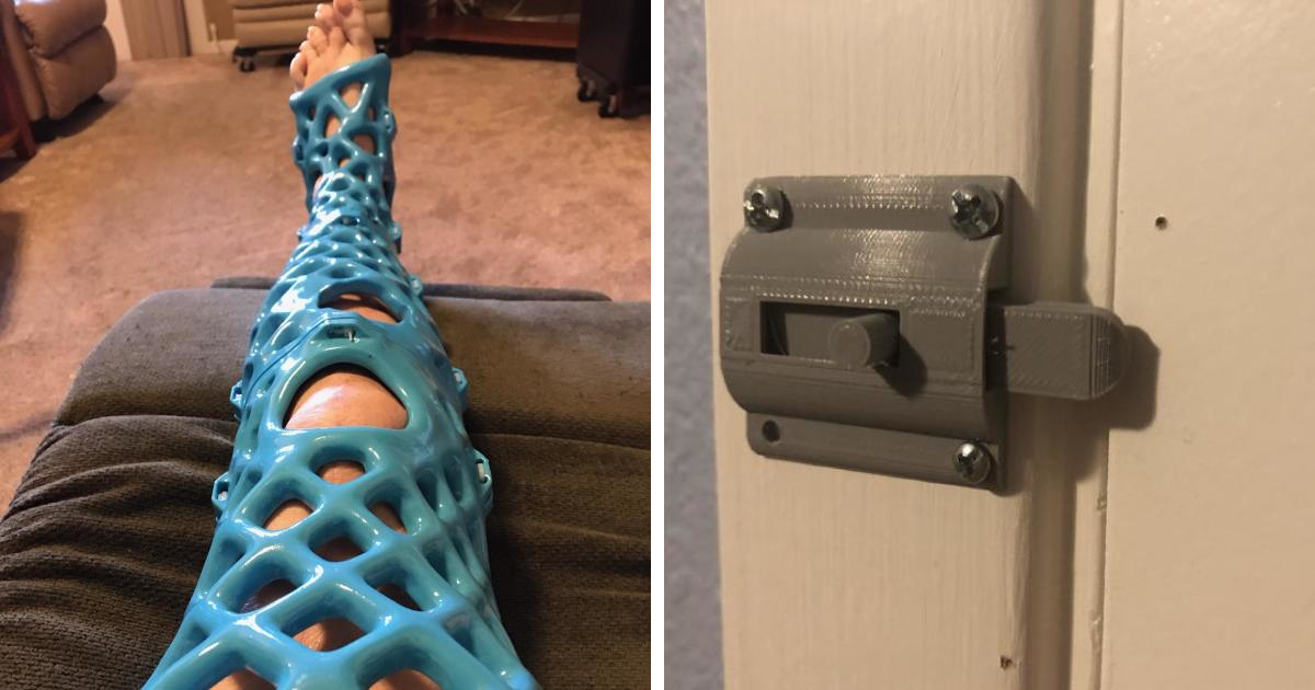
3D scanner able to quickly capture the size and shape of complex models. Due to the presence of physical objects, it can help to significantly speed up the design. The ability to copy and reshape models allows you to print parts for all kinds of existing equipment. For example, printed fixtures can be used to secure a drill or saw, as well as to ensure precise assembly of parts. Create tight-fitting, reusable masks for sandblasting, painting or engraving.
In this article, we will talk about reverse engineering a vent and explain how to scan a model for 3D printing. You'll also find tips for using reverse engineering tools here, from CAD software to 3D scanners and 3D printers.
To learn more about 3D scanning processes and technologies, download our white paper.
Download technical report
Looking for a 3D scanner for your 3D printer? Check out our guide to choosing the right 3D scanner for your 3D printer.
One of the main challenges of converting physical objects to digital ones is the incompatibility between two different types of 3D models: polygonal and solid .
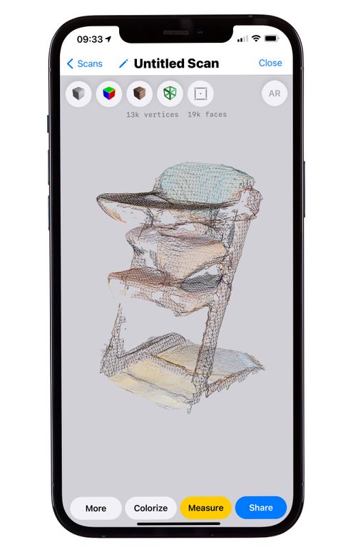
The 3D scanner generates a polygon mesh rather than a structural solid model. To modify a polygon model, you must convert it to a solid model.
The output from the 3D scanner will be polygon model in STL format, which is supported by most 3D printers. A polygon mesh is a collection of vertices and faces that define the shape of an object. It contains almost no information about the object, except for data on the position of the edges that determine the shape.
Engineers typically work with solid models that contain encoded information about the design of an object. With CAD, you can resize one element and update the rest of the model to reflect those changes.
Meshes do not contain information about the structure of the object, so CAD programs such as Solidworks and Onshape do not allow you to modify them directly. To make changes to the basic design of a scanned model, the mesh must be converted to a CAD drawing. It is this process that is called0153 reverse engineering .
Reverse engineering is used to create new models based on existing ones when the original CAD design is not available.
For example, you can create replicas of damaged parts or use the complex surfaces of existing objects to create printed fixtures for customizing mass-produced and handmade items.
Let's walk through the process of building a prefabricated jig for the Volkswagen Golf vent.
Spray the object with an anti-reflective spray to improve scanning accuracy. Even a slight sheen can degrade the quality of the scan. Be sure to treat the reflective and transparent surfaces of with a matte finish.
Use anti-reflective spray to improve scan quality.
Use a high precision 3D scanner to capture all important parts of the model. Desktop light and laser scanners produce results with an accuracy of ±100 or better.
Find out how to choose a 3D scanner for your application in our white paper on 3D scanning:
Note : An object that has dimples sometimes needs to be rotated and scanned multiple times.
Some scanners generate mesh files that are too large to work with.
The scanner software allows you to correct small imperfections and make the image easier to edit in CAD. Try to reduce the model as much as possible, keeping all the important details.
Tip : Use the Meshmixer to edit the mesh.
Import the mesh into CAD software to access reverse design tools. Use Geomagic for Solidworks for complex organic shapes.
Xtract3D is a more economical and lightweight alternative for simple flat surfaces.
Move and rotate the mesh to align it with the current structure elements.
Tip : Make your drawings easier by rotating the scanned model and aligning it with orthographic projection directions.
Three methods of mold extraction are available in CAD to create a solid model: semi-automatic surfacing, automatic surfacing, and manual copying.
Semi-automatic surface creation
Complex curved surfaces are difficult to create manually. To do this, you can use the semi-automatic creation function, which generates surfaces based on areas obtained by scanning. In this case, the accuracy of the digitized surface depends on the sensitivity settings of the scanner.
Tip : Geomagic for Solidworks copies the surface using 3D model curves. Use the "brush" to manually add or remove areas on the image.
You may need to repeat this process several times with different sensitivity settings to capture all surfaces. They can then be cut and joined to create an editable solid model.
Use semi-automatic surfacing to create curved shapes if you need maximum editability and edge precision later on.
Formed surface after cutting.
Automatic generation generates a solid model from any closed mesh. This feature allows you to remove and add regions to the generated surface using standard CAD tools, but makes it difficult to move the main elements on the body itself.
This method is fine if you don't need to place the edges manually.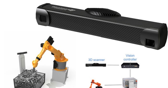 So, when scanning a part of the human body to create non-standard ergonomically shaped products or making fixtures for repeatedly modifying a handmade object, automatic surface creation will reduce modeling time.
Note : Compare the results of automatic and semi-automatic surface generation. Some precision is lost, especially around sharp edges.
Simple features such as tabs, holes and pockets are usually easier to redraw using the scanned model as an example. Reverse design software allows you to create sketch planes aligned with flat surfaces and extract mesh cross sections to copy the shape of the original object.
Once a scanned image has been converted to a solid model, it can be removed from another solid to create a fixture that will hold the original part securely.
In the design of the new deflector part, the dimensions of the scanned model were used with curves extracted using semi-automatic surface generation.