3D print lid
How to Design 3D Printed Snap Fit Enclosures
If you’re a product designer or an engineer, chances are you’ll need to make a custom enclosure at some point. This might be a simple container to keep small items organized or a fully functional 3D printed prototype to show stakeholders or test before moving to injection molding.
With CAD software and a desktop 3D printer, you can create a custom 3D printed snap-fit enclosure with interlocking parts in five easy steps.
White Paper
Looking for a 3D printer to realize your 3D models in high resolution? Download our white paper to learn how SLA printing works and why it's the most popular 3D printing process for creating models with incredible details.
Download the White Paper
Sample part
See and feel Formlabs quality firsthand. We’ll ship a free sample part to your office.
Request a Free Sample Part
Measure your electronic component (left). Begin your 3D model with basic boxes (right).
For this project, we’re going to make a case for a Pine 64, a single board computer (download the .STL file on Pinshape to follow along). This tutorial uses Solidworks because of its popularity in product design and engineering, but you can use a similar 3D design software.
First, use digital calipers or a ruler to measure your electronic component. We like to start enclosure designs by accurately reverse-engineering the PCB, measuring the board size, the location of mounting holes, and any ports or plugs that will need to be accessed through the enclosure. You might want to simply measure the overall maximum dimensions as a box, but it’s essential to know exactly where the main features are so that you can accommodate them. In Solidworks, reproduce these measurements as a grouping of basic boxes in a single part file.
In Solidworks, the enclosure is best designed as an assembly, with each half of the enclosure modeled as a separate part. Starting with the base half of the enclosure as a new part, the first important decision is to determine how much of a tolerance to have between the perimeter of the PCB and the enclosure. This depends on the 3D printing process you're planning to use to 3D print parts. SLA and SLS 3D printers are highly accurate, so you can tighten the tolerance to 0.5 mm without much risk.
A desktop FDM 3D printer may warp your design and lift it off of the print plate, so you should allow a larger tolerance of 1.5-2 mm to ensure that the PCB will still fit inside even if the walls are somewhat distorted.
Read our in-depth guide about FDM vs. SLA 3D printers to learn how they compare in terms of print quality, materials, applications, workflow, speed, costs, and more.
Add space between the perimeter of your electronic component and the enclosure (left). Build the walls of the bottom enclosure in your 3D model (right).
Our next step is to start cutting away the openings for the ports. One common mistake is that you will only cut away just enough material to expose the port connection, be it a USB or HDMI, without taking into account that many cables around the male connector can be quite bulky and need to reach into your enclosure to connect to the port (especially if the port is set in from the edge of the PCB, farther away from the enclosure). So it’s best to be generous with the port openings. An extra 2 mm all the way around is a good starting point.
Add extruded cuts and cutouts to the bottom enclosure to fit ports.
As you can see in the image above, we included extruded cuts, which go all the way from the top, and one cutout for a Micro SD card. The reason that some of the cuts reach the top is that the ports on the board stick out beyond the edge of the PCB, so in order to fit the PCB, we need to allow room for them to slide down. We will close some of these off with our top enclosure part, but you could choose to create a larger bottom enclosure so that the entire PCB and ports fit inside. Just be aware that you will have to push your connecting cables further inside the enclosure.
In general, the top enclosure mirrors the geometry of the bottom enclosure.
Now that you’ve completed the bottom enclosure, the top section is easy. The above image shows the effect of the parting line running around the perimeter between the two enclosure halves. The top enclosure has had the same treatment of cut details to accommodate some of the taller ports, as well as the addition of material to close off some of the gaps left by the bottom enclosure. We also added an optional sunken middle section.
White Paper
Designing for proper tolerance and fit lowers post-processing time and ease of assembly, and reduces the material cost of iteration. Download our white paper to learn more about tolerance and fit in 3D printing designing functional 3D printed assemblies.
Download the White Paper
With a basic internal cantilever snap, you can lengthen the amount of plastic engaging into the snap for a stronger lock.
There are many designs for snap-fit components, but we opted for a basic internal cantilever joint. Above you can see the main details for the snap-fit design, which is exactly the same on both sides (male and female parts) of the enclosure. Depending on the space you have to work with, you can lengthen the small protrusion engaging into the snap cavity to create a stronger lock. In our snap-fit assembly, it's only 1.2 mm, but 2 mm or more would be much more secure. In this particular design, the pins on the PCB take up a lot of room, so the lock is designed to just squeeze in while providing enough force to hold the enclosure together. The cantilever joint is extruded 20 mm long, which adds to the strength.
This sectioned exploded view shows the snap details on each side.
Above you can see a sectioned exploded view of the snap details on the enclosure, along with the PCB showing the location of the pins (in black), which limit the size of the cantilever joint. Alternatively, instead of the snap cavity hiding inside of the bottom enclosure, you could cut this detail through to the outside, allowing your snap-fit joints to be longer.
Lugs are small extrusions that slide within the opposite enclosure to secure the two halves.
Add lugs to your design to keep the two halves from sliding. Lugs are small extrusions that insert into the opposite enclosure. Because we created two snap-fit joints on opposite sides, you might need these on just the two blank sides. For this larger case, we put them in each corner. The material extrudes only 3 mm down, but this is enough to prevent movement on 3D printed interlocking parts.
This basic snap fit enclosure can be adapted for nearly any small electronic component.
While this might be enough detail for your project, a few added features can bring your 3D printed enclosure to life. For this design, we extruded some text for the Pine 64 name and details like the SD card location. We included the Pine 64 logo as a visual feature, but also to provide ventilation on the top since these boards can heat up. Plus, these details reduce the amount of 3D print material used.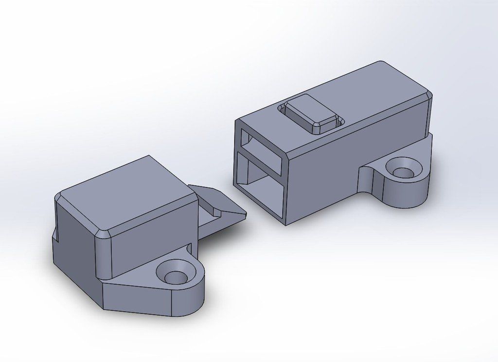 Finally, a couple of grip details where the snap-fit joints are located helps indicate where to press your fingers to open the enclosure.
The final design includes unique features along with the snap fit enclosure, ready to be 3D printed.
Webinar
Join our materials experts as they discuss how the incredible properties of PU Rigid Resins paired with the benefits of 3D printing are eliminating previous limitations of traditional polyurethane manufacturing. Take your 3D printed snap fit enclosures to the next level with two new, true polyurethane materials.
Register for the Webinar Now
SLA 3D printing offers a wide variety of engineering materials for creating accurate 3D printed parts and prototypes and help you reduce costs, iterate faster, and bring better experiences to market.
Want to see what you can create with a SLA 3D printing? We’ll ship a free 3D printed sample part to your office.
Request a Free Sample Part
How do you design snap-fit joints for 3D printing?
What are snap-fit joints and how do they work? This in-depth guide discusses the benefits of 3D printing snap-fit connectors and clips and gives design and material recommendations for designing custom parts with snap-fit joints.
Snap-fit joints are a quick and easy way to connect two 3D-printed components by using interlocking features. Not only are they a low-cost and time-saving connection method, but they can also reduce the number of parts needed in an assembly. Plus, they offer the possibility of rapid assembly and disassembly.
This article covers the basics of snap-fit joints (also called connectors and clips) for 3D printing , what to consider when designing snap-fits with plastics and thermoplastics and which 3D printing process is optimal for manufacturing the best snap-fits.
Does Hubs have a snap-fit tutorial?
Before (or after) diving into this comprehensive guide, check out this nifty tutorial on designing snap-fit joints for 3D printing.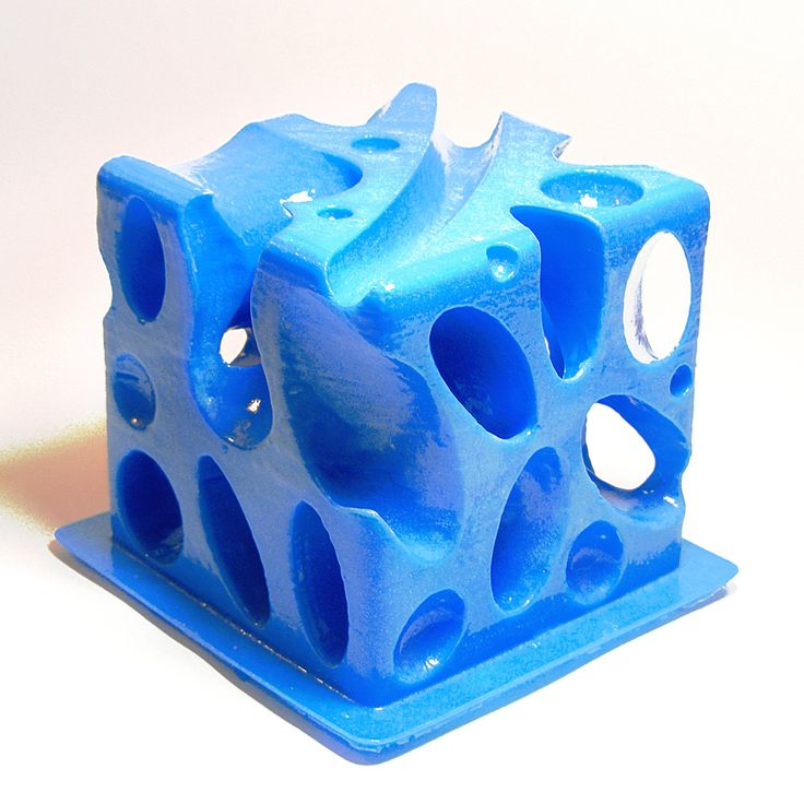
What are snap-fit joints (or connectors/clips)?
A snap-fit joint is a cost-effective and relatively simple method of attaching two 3d-printed plastic components. Also known as a connector or clip, a snap-fit generally consists of a small and bendable protrusion, like a bead, stud, or hook, and a mating depression that deflects and catches the protruding feature. The two features clicking into place create a robust interlocking connection.
Once the features have clicked into place, an undercut holds the two components of the snap-fit together. Depending on the shape of this integral undercut, snap-fit assemblies can also be designed to make the interlocking connection permanent. A well-designed snap-fit joint with the right material can be used quite a number of times without any noticeable mechanical fatigue.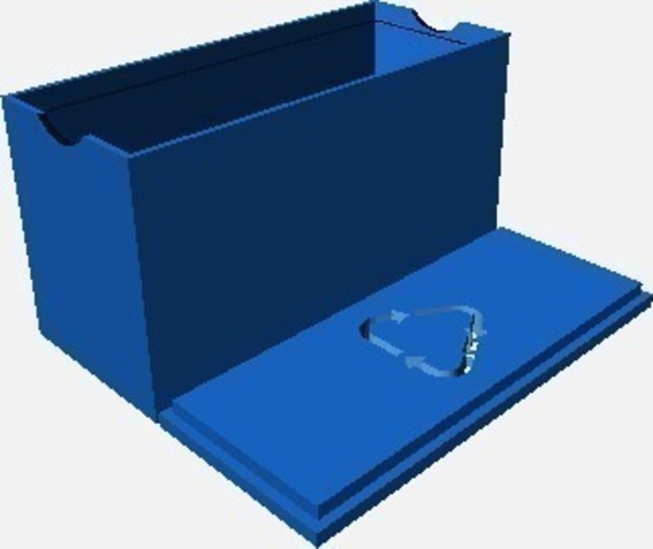
There are plenty of types of snap-fit types and geometries that follow the basic principles of two interlocking components.
Common types of snap-fits: cantilever and annular joints
The two most widely used and commonly effective types of snap-fit connectors are cantilever and annular joints. Let’s break these down.
Cantilever snap-fit joints
The most common snap-fit joint is the cantilever, consisting of a protrusion (some type of bead or hook) on one end of the component and a structural support feature at the other end. This protrusion is placed into an opening and bends back to lock the connection into place.
Cantilever snap-fits are easy to design and intuitive when it comes to assembly and disassembly. For many applications and cases, cantilevers are the most cost-effective way to connect to components.
A cantilever snap-fit on a 3D-printed enclosureAnnular snap-fit joints
Annular snap-fit joints use a hoop strain to hold a pressed part in place.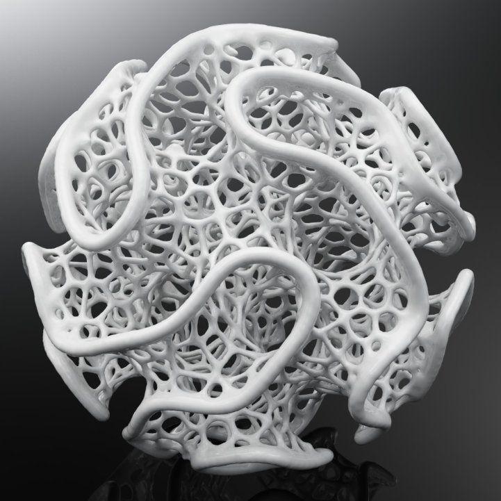 Common examples of annular snap-fits are bottle and pen caps. With annular snap-fits, it’s possible to create a waterproof seal around the joint.
What are the advantages of snap-fitting with 3D printing?
While injection molding is often seen as the more robust way to produce snap-fit joints, 3D printing is a viable alternative (and even a go-to) with the right design and materials.
3D-printed snap-fits don’t have any of the design limitations associated with injection molding—for instance, draft angles, separation lines, wall thickness and undercuts—and can be designed and altered with ease. This makes them ideal for rapid prototyping, where clearance and fit are critical. This is why designers generally use 3D printing for snap-fits in enclosures .
Snap-fit construction for a DIY loudspeakerWhat materials are used for 3D printing snap-fit joints?
Every 3D printing process has its pluses and minuses when it comes to producing parts with snap-fit connectors.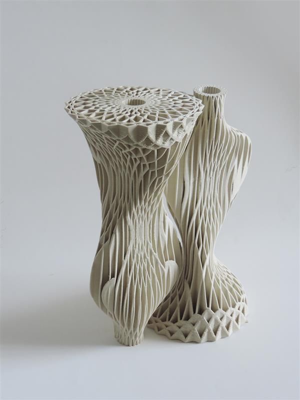 This is due in part to the materials used with each of the major additive manufacturing technologies.
FDM is the most cost-efficient way to manufacture snap-fit connectors. While it’s definitely effective, the process has lower accuracy than other printing methods. If you choose FDM, we recommend using strain-resistant materials, such as ABS, Nylon and TPU.
SLA resins are also a viable option for making snap-fit joints, but they are relatively brittle. Using resins may increase the chances of the snap-fit breaking after repeated use. We recommend durable SLA resin if you print snap-fits with this technology.
SLS is more suitable than FDM and SLA for printing functional snap-fit prototypes and end-use parts that will be opened and closed many times. The best material for maximum tear resistance is SLS Nylon.
Similar to SLS, MJF is optimal for manufacturing snap-fit connectors. MJF produces robust parts from Nylon PA 12 and a few other nylon and polypropylene options. What’s important to remember with MJF is that there are several design guidelines to follow to achieve the best results. For instance, we recommend a minimum thickness of 1 mm at the base of the cantilever and a minimum common overhang depth of at least 1 mm.
Explore pricing options for every 3D printing process
FDM SLS MJF SLA
Designing snap-fit clips isn’t the same for all technologies, materials and applications. Engineers faced with snap-fit design for 3D printing often encounter a few key challenges. Here we cover the main ones.
-
Sharp corners in the design may add stress to a cantilever, which may raise the probability of the joint breaking off.
-
Constant stress on plastics and thermoplastics tends to cause creeping (deformation). Creep will eventually weaken the snap-fit or even compromise it entirely.

-
Misplaced gaps on parts will cause tolerance issues, in turn making it harder for components to fit together.
-
The more you assemble and disassemble snap-fit joints, the more likely you are to come across fatigue failure.
In general, snap-fits will encounter the most stress during attachment and should return to their neutral position once the joining process is completed. Depending on the shape of the undercut, snap-fit assemblies can also be designed to make them permanent. A well-designed snap-fit with suitable material can be used many times without any noticeable fatigue.
What are the right tolerances for snap-fit joints?
3D printing properties can vary quite a bit, from printer calibration and materials to the printer technology itself. Because of these varying factors, there are no strict tolerancing rules for printing snap-fit joints and connectors.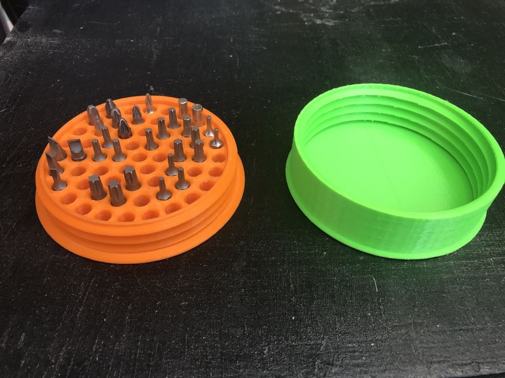
While there are no set rules, we do recommend the following optimal tolerances for different types of 3D printers.
-
For FDM (fused deposition modeling): 0.5mm
-
For SLA (stereolithography), SLS (selective laser sintering) and MJF (Multi Jet Fusion): 0.3mm
When designing snap-fit joints for 3D printed parts, it is important to consider features that will reduce stress and strain on the snap-fit assembly. Here are some of our best practices for designing snap-fit joints for 3D printing.
Taper the design
A snap-fit cantilever with a constant cross-section has an uneven distribution of strain. We recommend reducing the cross-section of the cantilever beam over its length.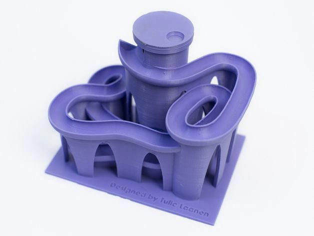 This uses less material and results in more even distribution of strain across the entire cantilever.
Fillet the base of the cantilever:
Adding a fillet at the base of a cantilever will help distribute stress over a broader area, resulting in a stronger connection between snap-fit components. The radius of the fillet should be at least 0.5 times the thickness of the cantilever’s base.
Increase the width:
Increasing the width of the clip, if it’s feasible given any design constraints, makes the design stronger. You may need to iterate several times to get the right part stiffness, and remember that the clip should be at least 5mm wide.
Deflect during assembly:
To help reduce stress and improve the strength of the connection, make sure that the snap-fit cantilever is only deflected during assembly rather than when the components are connected.
Consider build direction:
If possible, avoid designing snap-fit cantilevers that are built up vertically (in the z-direction). These are inherently weaker due to the anisotropic nature of 3D printing.
Add lugs:
Consider adding lugs to your assembly to assist with the alignment of components and to transfer some of the shear load your snap-fit clips may be subjected to.
-
Sound design principles can make or break your snap-fit joints. Remember to implement good design practices that reduce stress (fillets, build direction and locating lugs) and strain (tapered profiles and cantilever width).
-
Choose the right tolerances for different 3D printers. Use 0.5mm tolerances for FDM snap-fit connectors and 0.3mm for all other 3D printing processes.
-
Do your materials homework beforehand. Prototyping plastics are ideal for design confirmation, but they are typically weaker than SLS or material jetting materials.
 Think about functional or end-use materials for applications where the connector will be opened and closed repeatedly.
To explore 3D printing further, check out our full guide for a comprehensive overview and detailed design and manufacturing tips.
Ready to transform your CAD file into a custom part? Upload your designs for a free, instant quote.
Get an instant quoteHeadlamp cover | 3D printing studio
Completed works
The headlight cover is one of the parts of any car that is lost or broken when installing xenon or replacing low / high beam lamps. It is difficult to buy such a part, given that they are not sold separately from the block headlight. The option to buy a used part is possible if it is available.
What if the car is rare, the original headlight cover is very expensive or not available? There is a solution. Headlight cover is made by our studio to order! We print the part on a 3D printer, copying it from the one that is available.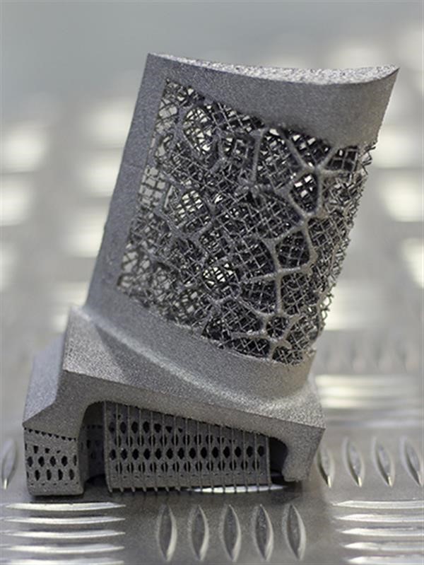 If the part is lost, then we scan from a symmetrical part. And in cars, parts often have their counterpart.
For computer modeling, nothing is easier than making a symmetrical part. If there is no such detail, then we simply look for where it can be scanned or copied. In our case, the existing, albeit unusable, block headlight cover was sufficient.
3D scan headlight cover
Preparing the part for 3D scanning:
- clean;
- Matting with a special rinse-off spray;
- set reference points;
- we scan;
- we correct the obtained 3D model to the required result according to all design and 3D printing requirements.
Headlight cover AUDI
In our case, the headlight cover of an AUDI car was damaged when installing xenon.
The owner requested to make two of the same headlight covers, because. he failed to find and buy original covers.
A sample part was received for this order. The photo shows that the cover has damage in the form of a hole made.
The above scanning procedure was carried out. The 3D model of the cover was corrected and as a result the mathematical model shown in the picture was obtained:
AUDI headlight cover. Part Manufacturing Requirements
Black ABS was selected for printing the part.
Print layer: 0.3 mm.
Part density: 100%.
Part volume: 43.6 cm3
Print material consumption: 48 g.
Cost of two parts: 1000 rubles.
Postprocessing: Remove material.
Headlight cover AUDI. End result
Customer feedback
The first sample of the cover was easily installed on the block headlight - it fit like a native.
After road testing, the customer confirmed the production of the second headlamp cover. The manufacture of such spare parts as a headlight cover for cars has become affordable even for domestic car owners in terms of technical characteristics of materials and manufacturing costs.
Feedback form
Colleagues, we try our best to advise our clients. Because of this, the duration of the conversation may affect the busyness of the telephone line, even though it is multichannel. If you are unable to reach us by phone, please use the feedback form. As the requests are processed, our specialist will contact you.
Telephone
E-mail *
Product loads:
Impact
Static
Static with constant load (e.g. screw tightening)
Dynamic
Ask advice
The thickness of the filling layer:
0.1 mm
0.2 mm
0.3 mm
Ask the Council
Filling out the object:
Ask advice 10% 20% 30% 40% 50% 60% 70% 80% 90% 100% Select the percentage of product coverage
Product color:
Natural White Gray Black Other color Any color Please specify desired color
Product post-processing:
Not processed.
Support Material
Chemical Processing (STOLLASHING STATE)
Ask advice
Operating temperature:
to 60 ° C
to 80 ° C
to 100 ° C
9000
Ask the Council
Material:
Hard
Soft
Ask for advice
Protective cover for Oculus Quest 1 lenses (3D printing, rubber) black
- Description
- Reviews
Oculus Quest 1 lens protector (3D printed, rubber) is an accessory that is guaranteed to protect your VR glasses displays from the sun's rays. When the latter get on the lenses of the VR helmet, the screen matrix burns out, which leads to damage to the display and, in the future, to the need to replace it. The case also serves as an additional protection for the lenses and the inside of the glasses from dust.
By default, the protective cover will be made in black, but if desired, you can order any color.
Oculus Quest 1 Lens Cap Benefits:
- Reliable protection. Protective cover for Oculus Quest 1 lenses will protect the screen from fading, and the lenses themselves from dust and scratches.
- Ease of use. The protective cover is easy to fit into the headset and just as easy to remove.
- Full compatibility. Protective case was specially designed by for the Oculus Quest 1 VR headset, so it fits perfectly.
Contents:
- Protective cover for Oculus Quest 1 lenses (3D printing, rubber) – 1 pc. 14 days
VR goggles and rides business customer reviews
Ilya Kulte
Almaty
https://vk.com/id8258671
Ilya's review:
“Good afternoon! I purchased 4 sets of Oculus, for a company in Kazakhstan. Thanks for the fast shipment, everything came to Almaty very quickly)
True, there were troubles with the installation of games, but they explained everything how and what) According to the documents, everything is OK, if something is missing or needs to be changed, they do not a month, but within 30 minutes) This is a really big +!
Thank you again!!!”
Roman Chirkin
Sarov (Nizhny Novgorod region)
Roman's response:
“Alexey, good afternoon. For your needs, I am sending a photo of the attraction from Sarov, write a review yourself - everything suits me.”
I didn't write a review on behalf of Roman 🙂 I'll tell you how everything was in my own words. Roman did an attraction in Sarov. He himself came to Tambov for glasses with his system unit, they connected everything, checked it, signed the documents. The rack was made in Sarov according to our drawings, we made the cart. Until now, we communicate on various issues about virtual reality. Great client I must say!
GOSTEV ALEXEY
Valery Kurganov
Khanty-Mansiysk
https://vk.com/vvkur
“Seeing the SEC SECULUS OCULUS OCULUS OCULUS OCULUS business began to look for where to buy glasses. There are few sites with a sale and everywhere they ask to make an advance payment and the cost is different for everyone. I ordered a helmet a week later, I already have a price that is really high, but it is removed from sale in Russia and Ukraine, such prices are probably from here. In general, I select games and play with the whole family, everyone is interested. Every day developers make more and more new games for Oculus Rift Development Kit 2 (DK2). And in order to set it up, I had to suffer, but thanks to Alexei (the seller of points), he suggested sites for downloading games and who to contact to set up points. In general, it’s not a deceit or a divorce, everything is clear, you don’t have to worry about being deceived. ”
”
Alexander Ershov
. Tambov
https://vk.com/kaskader68
Review of Alexander:
“I first saw a video with these miracles with glasses and thought that it was not bad for business, started looking for glasses on the Internet, searched a lot of sites, everywhere they asked for money in front, it alerted me, I was already hung up, but it wasn’t there))) I stumbled upon this group and was very pleased that payment upon receipt, contacted with Alexey, made an order, received the goods, paid and received a very useful BONUS! for both the entrepreneur and the user, the right links with a bunch of games, necessary applications and a video with a webinar. The glasses work properly, packed securely and for all this, a huge thank you to Alexey! =)"
Albert Groshev
. Yugorsk
https://vk.com/groshevalbert
Consulting Alberta: Many thanks to Aleksey GOSTEV for help in the acquisition of OCTED DKT , customization and support! Delivery received by courier, without delay and extra costs. From tomorrow we start working and earning! Personally, I advise you to purchase equipment from Alexey. Thanks!"
Maxim Chernyshov
Tambov
Maxim's review:
“I bought glasses from Alexey, everything is fine, very responsible seller! there can be no talk of scammers, everything as promised was fulfilled in good faith! I recommend!"
Attraction in Tambov, shopping center "Auchan", st. Soviet, 194b.
Zhargal Bazarov
Ulan-Ude
https://vk.com/id157462678
Review Valery:
“I advise you to buy from Alexey!!! I recently ordered dk2 glasses, surprisingly they arrived in Eastern Siberia in 6 days, I didn’t even have time to prepare money, I thought they would go as always for at least two weeks)) And most importantly, you don’t have to pay any prepayments, etc., i.e. the risk that you if you lose your hard-earned money, they equal zero . .. And so Alexei always helped on the Internet and on the cell phone day and night, because we have a difference of 5 hours with Moscow. To be honest, I didn’t regret the money, it’s better to overpay than wait 2 months or even be left without them. Moreover, the New Year season is just beginning!!!”
Olga Nastrova
. Vologda
https://vk.com/id58254460
attraction in Vologda, Ileland store http://ilandstore.ru/
Reviews of Part Buyers of virtual reality glasses
Konstantin Engraf
Primorsko-Akhtarsk
https://vk.com/id17081416
Review of Konstantin:
“Ordinary birth. Everything is at the highest level, the kit is complete, new + I really liked the responsiveness of Alexei. You can have no doubts about the evenness of this topic and the seller.”
Alexey Trofimets
, Krasnoyarsk
https://vk.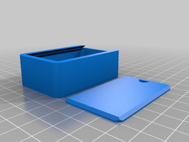 com/melomanich
pay upon receipt of the parcel. An official purchase and sale is made with the seals and signature of the seller, you only need data to receive the parcel: the address and city code and passport data for registration of the sale. The parcel came to me very quickly, in just 4 days Tambov-Krasnoyarsk. I am very pleased with everything: honestly, promptly, provides assistance in case of problems.”
You can read other reviews and leave your own in the reviews section in our VKontakte group.
Delivery and payment
Delivery: To any location in Russia, Belarus and Kazakhstan by transport companies PEK, Business Lines, Baikal Service, etc., courier services CDEK or EMS. Cost: according to the tariffs of transport companies.
Payment:
0039 2. Cash (cash on delivery) upon receipt at EMS and Russian Post,
3. Payment before shipment according to the sales contract (for your safety, we conclude the contract without fail): bank transfer, transfer to card, Webmoney, Western Union , Qiwi, etc.


