Planetary gearbox 3d print
3d Printed Gears - Etsy.de
Etsy is no longer supporting older versions of your web browser in order to ensure that user data remains secure. Please update to the latest version.
Take full advantage of our site features by enabling JavaScript.
Find something memorable, join a community doing good.
( 1,000+ relevant results, with Ads Sellers looking to grow their business and reach more interested buyers can use Etsy’s advertising platform to promote their items. You’ll see ad results based on factors like relevancy, and the amount sellers pay per click. Learn more. )
3D Printed Differential Planetary Gearbox 43.
-
No Prints Yet
Be the first to upload a Print for this Design!
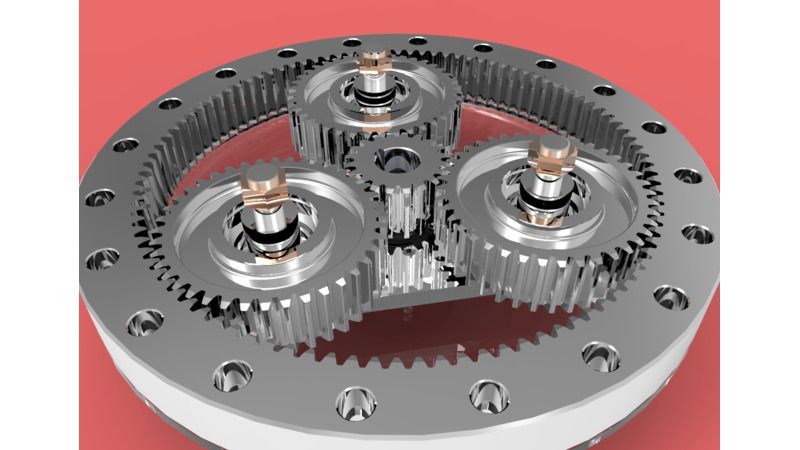
Summary Updates! Uploaded the Rotating Base http://www.thingiverse.com/thing:2166517 3/10/17- Youtube Video! https://www.youtube.com/watch?v=RcUrgxrOqVo&feature=youtu.be 2/27/17- I designed a one piece sun gear for this, one version with a large drive gear on it and one version with a 5mm D shaft hole, the one piece sun gear is compatible with the 3 & 4 module planet gears. if your using the 4th module you may choose to use the #2 sun gear in module 4 in conjunction with this. Using the one piece sun is a good upgrade for this as it cuts down on backlash. I designed this gearbox for my Modular Robot Arm Project, check it out! : Origional model http://www.thingiverse.com/thing:2105057 EZ Print model https://www.thingiverse.com/thing:2153317 Mounting Base For Testing http://www.thingiverse.com/thing:2154052 Use the origional model for attachment to the mounting base, the EZ print version has no attachment method for that.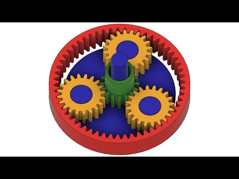 The EZ print model is better used between two joints. Both models are 100% compatible with this gearbox and each other This gearbox is an update to my previous gearbox, the main differences being that this one has a much lower backlash setting (.1mm VS .25), uses a different helix angle, has more external grip teeth, the Rings Gears are not as wide, and has a optional extra module. Assembly ------------------------------------------------------------------------------------ Align the planet gears in order as shown in the main picture, insert a sun gear, Snap Ring Gear #1 on, Inset all sun Gears, snap the other 2 or 3 ring gears on, also, you will need to close the gap in the rings before you spin this gearset or else it could skip teeth and get out of alignment, for this i have included the ring closures, that fits over all the rings For any instructions i may have missed, please refer to this : http://www.thingiverse.com/thing:2081324, this gearbox is very similar in concept. How it works ------------------------------------------------------------------------------------------ When you rotate Sun Gear #1 (The sun Gear with the D-Shaft hole) The Planet gears orbit that gear causing Sun Gear #3 to rotate at the exact same speed as Sun Gear #1 Now, When the Planet Gears make a full 360 Degree rotation around the Sun Gears, Ring Gear #2 ( and the Optional Ring Gear #4) will move 27.
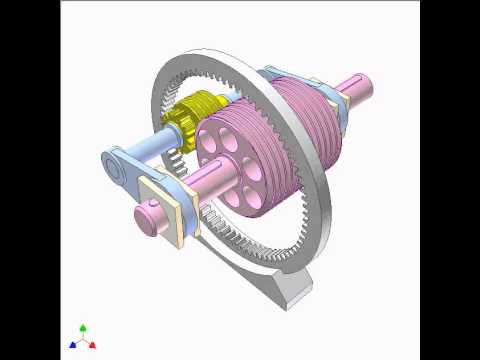 7 Degrees, ( 2 Teeth) The other important thing to realize here is that Ring Gears #1 & #3 will be at the same potential and Ring Gears #2 & (Optional #4) will be at the same potential The use of Ring Gear #4 and the 4 Module Planet Gears is optional and used to increase the amount of torque this gearbox can transfer, as well as to decrease the amount of (radial?) load on each gear, think of it like a door hinge. When you use the 4th module you should re-use Sun Gear #2 to space out the planet gears within Module #4 ////----------////----------How to Design your own--------////----------////----------////---------- If you would like to design a gearbox like this to integrate into your own project, just follow these somewhat complicated and poorly written instructions. You will need two planetary gear sets, the closer the number of teeth, the higher the output gear ratio will be. The following design constraints are very important: But First, design tips: The more planets, the harder it is to meet all the constraints.
![]() 2: using gears with lots of teeth can achieve very high gear ratios(500:1+), and higher ratios than i have designed have been achieved by others, such as Emmet. Gears with a lower pressure angle have much less friction, and last longer, but aren't as strong. I am experimenting with newer designs with 20 deg pressure angle and they're very promising. You will need to study the gear tooth combinations that work properly in a planetary gearset, keep in mind that not every combination of gears will fit together, and not every combination that fits together will allow for evenly spaced planets (and that IS necessary), to find gear combinations that fit these two design requirements, use these two equations. For Figuring Gear Combinations that fit together: Teeth_Sun + (Teeth_Planets*2) = Teeth_Ring_Gear For figuring if the planets (pinions) can perfectly evenly spaced: (No_of_teeth_sun + No_of_teeth_Ring) / Number_of_pinions has to be integer. Keep in mind that those two equations will not prevent you from making planet gears that overlap, heres a quick tool for that: http://www.
2: using gears with lots of teeth can achieve very high gear ratios(500:1+), and higher ratios than i have designed have been achieved by others, such as Emmet. Gears with a lower pressure angle have much less friction, and last longer, but aren't as strong. I am experimenting with newer designs with 20 deg pressure angle and they're very promising. You will need to study the gear tooth combinations that work properly in a planetary gearset, keep in mind that not every combination of gears will fit together, and not every combination that fits together will allow for evenly spaced planets (and that IS necessary), to find gear combinations that fit these two design requirements, use these two equations. For Figuring Gear Combinations that fit together: Teeth_Sun + (Teeth_Planets*2) = Teeth_Ring_Gear For figuring if the planets (pinions) can perfectly evenly spaced: (No_of_teeth_sun + No_of_teeth_Ring) / Number_of_pinions has to be integer. Keep in mind that those two equations will not prevent you from making planet gears that overlap, heres a quick tool for that: http://www.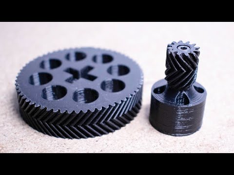 thecatalystis.com/gears/ Once you have decided on a number of planets and your two planetary gear combinations that you would like to use you need to model the gears, You will need to go off into your CAD program. When modeling the gears the most important design constraint is keeping the planets from each gearset at the same center to center distance. Use the following equation to align the planets from the two planetary gearsets with one another: Planetary Gearset #1 (Sun Gear Pitch Diamerer + Planet Gear Pitch Diameter) Must be equal to: Planetary Gearset #2 (Sun Gear Pitch Diamerer + Planet Gear Pitch Diameter) you can set the pitch Diameters equal in your cad program by adjusting the module(the number of teeth per mm) of one planetary gearset in contrast to the other. FYI the pitch diameter of a gear is the size of the circle that is made when it meshes with another gear. I.E. if the gear was a cylinder, rolling against another cylinder.
Say a word about the planetary gearbox
Good afternoon, in this article I will try to describe my experience and the method I have formed in developing a planetary gearbox.
Recently became the owner of a Flsun QQ-S 3d printer and began to slowly transfer plastic to all sorts of interesting and obscene things.
Like many other visitors to the 3dtoday website, I periodically have questions: what are the strength limits of plastic and what can be printed?
On one of the Russian-language youtube channels I found a whole playlist from a user who printed a winch on a 3d printer to lift potatoes and pickles with jam in the garage cellar (link) And here the idea of \u200b\u200brepeating this homemade product from the design stage arises in order to pump up your skills on modeling, before printing and assembly of the product, with subsequent testing of the winch. nine0003
This paragraph needs to jump back a bit and clarify certain points that led to the writing of this article.
After buying a printer, a certain conflict arises, which everyone decides for himself as the owner of a 3d printer. How to model a product? If only for yourself and a friend, then one set of software, and if you try to recoup the cost of a printer or at least plastic, then the number of available options narrows sharply. I mean use the software according to the user agreement. And so you still want to pay back your toy)) And here there is a choice between the light and dark side of the force. For myself, I made a key decision to model only in licensed software, i.e. software should be provided by the developer either free of charge, or paid for within the limits in which the toad allows me to roam. You can use commercial, paid software, but only within the trial period and only for review, after which the program will be deleted. nine0003
In the course of sorting through the available solutions on the market, both domestic and foreign, Fusion 360 was chosen. We have to admit that Autodesk knows how to get new users involved.
Now back to the winch, this winch uses several planetary gear stages to reduce the number of revolutions produced by the engine with a corresponding increase in torque on the output shaft.
In order to start designing the planetary gear, I explored the depths of Fusion 360 to find a function that, according to the parameters I specified, would model and display a ready-made gear model in the workspace.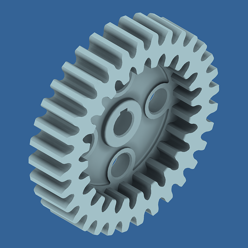 Naive) This function is reserved for paid large programs. nine0003
After that, I began to study the experience of more experienced comrades living on this site. In the course of studying the materials, I formed the following conclusions for myself (if I'm wrong, then correct me):
modeling takes place according to the principle of constructing a tooth and with a circular array we form the contour of a gear, which is then extruded;
gear profile generators are used in various editors, which are also extruded. nine0003
After examining the generators, I came to the curious conclusion that they are either simple or free. or more or less functional and became paid (for example, https://geargenerator.com/). Moreover, the latter, despite its good functionality, cannot generate the planetary gearbox I need.
Summarizing my own experience and the experience of many others, I found that in order to design a planetary gearbox, it is necessary to carry out a geometric calculation of the gearbox (module, number of teeth of transmission elements, number of satellites, pitch diameters, checking the transmission assembly).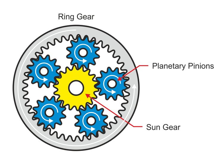 Moreover, I did not find free software for calculating these parameters. An excel file circulates through the expanses of Runet only for calculating the cylindrical gear. nine0003
on the basis of which the idea of the following algorithm arose:
-
We calculate the geometric parameters of the planetary reducer
-
Based on the calculation in Fusion, we form a gears
-
, as we need and use them for modeling the product
- 9000 profit
Now we start to dig how the planetary gear is calculated. I will not bore you with the details, for the calculation in excel I prepared a small table that helps to calculate the engagement. To use the tablet, you need to connect the add-in 'Search for a solution' in excel. nine0003
Immediately explanation, in the current form, the gear is selected according to the gear ratio and the number of teeth of the sun gear, if it is necessary that the number of teeth of the sun gear does not change, then the instructions (the file indicates how to do this)
How to use it and the whole algorithm of actions for creating a link:
1. Open the file
2. According to the instructions, fill in the initial conditions
3. 'Data' tab, call 'Search for a solution', click 'Find a solution'. nine0003
4. Get the required parameters. Here we are interested in the number of teeth of the transmission elements, the number of satellites and the center distance of the satellites (this is the radius on which the axes of the satellites are located)
5. Open fusion and go to the Fusion App-store, where we look for and install the following add-ons: Helical Gear and FM Gears
The trick is, Helical Gear is an add-on that forms helical gears, but in it you can set the angle of inclination of the teeth to 0 and get a spur gear, and FM Gears allows you to form a crown gear, you can also set the engagement clearance in Helical Gear, and in FM Gear is not allowed. nine0003
6. Run Helical Gear and fill in the parameters of either the solar or the satellite Helix Angle - the angle of inclination of the teeth - 0, Module
- the engagement module, Teeth - the number of teeth according to the calculation, Gear Thickness - the thickness of the tooth, the Backlash parameter is also important here - set the engagement gap to 0.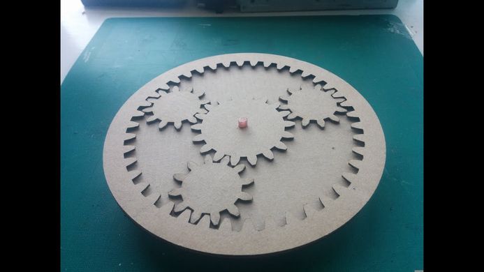 4 mm. Check the Preview box and see our beautiful gear, then click OK and the gear is created as a component at the origin.
7. We do this operation for another gear, we also indicate a gap of 0.4 mm. nine0003
8. Then we place them in space according to the purpose, the sun in the center, the satellite at a distance of the radius of the satellite
9. Create a crown gear. We launch the FM Gear add-on and go to the Internal Gear tab, the parameters to be filled are similar to the previous add-on, but there is no gap and it is necessary to set the outer diameter of the crown gear. Do not worry, if the diameter is not appropriate, the system will issue a warning and then you just need to increase it. Click OK and see the result in the form of the created component. nine0003
10. Please note that the gears after creation are located in perpendicular planes, with centers at the origin. Therefore, we turn them as we need.
11. We create a gap in the meshing of the crown gear, from the experience of printing, without this gap the gear did not fit on the satellites)).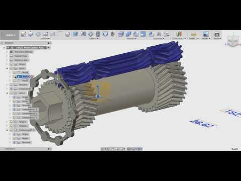 To do this, open the crown gear component, the easiest way is to create a new sketch on the gear plane, project the tooth profile onto it, then create an offset by 0.4 mm with the Offset command, then create the gear profile with a circular array and extrude a solid body. nine0003
12. You can additionally get confused and turn the gears beautifully so that the teeth do not intersect, but this is already for aesthetes.
13. The next thing is the simplest. Simulate the carrier, overtake the models in STL and send them to the slicer.
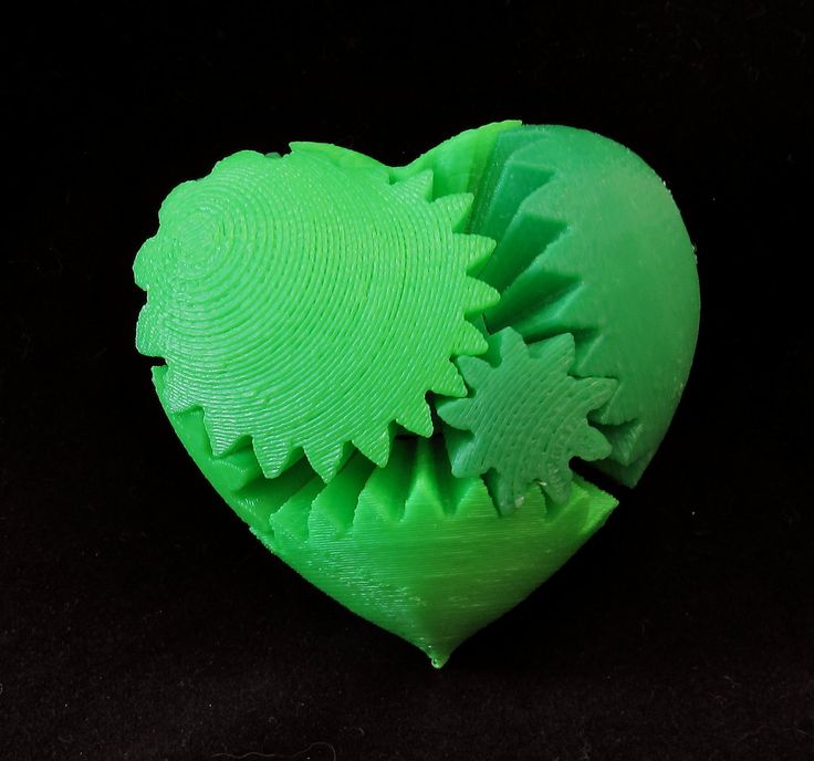
Printing and assembling the gearing.
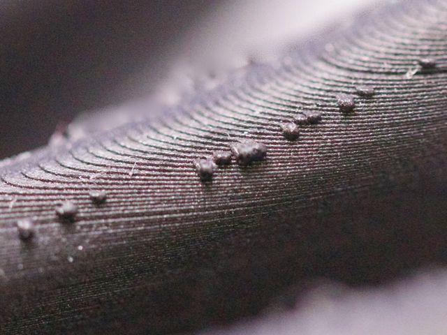
The photo shows the planetary gear, which was calculated using this Excel plate and assembled after printing.
What can I say, the gaps between the sun gear and satellites 0.4 each wheel turned out to be normal, between the crown gear and the satellite turned out to be too big, because during development, I set the crown gear offset to 0.5 mm. nine0003
As a result, this method of creating a planetary gear has a place to be. I also know that adult packages can build and calculate all this automatically. But, with the approach of using only licensed design software and not spending too much on licenses, it justifies itself. If anyone knows a simpler method for creating a planetary gearbox, then let me know, I will be glad to learn and apply))
Further plans to create similar plates for calculating bevel gear and spur gear. nine0003
Attached is the excel file. I just don't know yet how to upload it to 3dtoday.
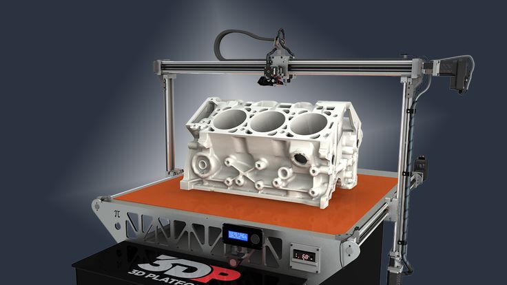
A mechanical engineer 3D printed a working gearbox for a Toyota engine (+ video)
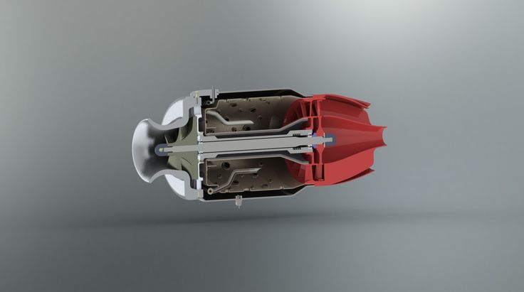
One of the unusual novelties is a 3D printed five-speed gearbox for a Toyota 22RE engine. The author of the work is mechanical engineer Eric Harrell from the city of Santa Cruz in California. His brainchild not only looks convincing, but is also a fully functional model.
In January, Harrell had already reverse-engineered a Toyota engine from scratch using a 3D printer (in other words, analyzed and reproduced its design).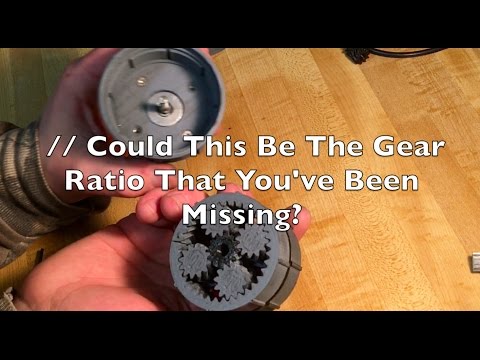 Thingiverse users and the American media have positively evaluated Harrel's project, and he decided to take his creation to the next level by supplementing the engine with a gearbox, also printed on a 3D printer. Harrell's two designs can work together to create a unique piece of 3D printed mechanical construction. nine0003
“The success of my first project, a four-cylinder Toyota engine, inspired me to get into the gearbox business,” says Harrell. “It's amazing how many people are interested in my work. I never thought that my design could generate such interest and, moreover, that people would actually print and assemble it, simply because it is a complex and time-consuming process. To date, eight people have already assembled the engine, and many are now working on it.” nine0003
In general, it will take approximately 48 hours of printing on a 3D printer to make all parts of the gearbox. After printing all the components, you need to assemble the structure according to the drawings provided by Harrell.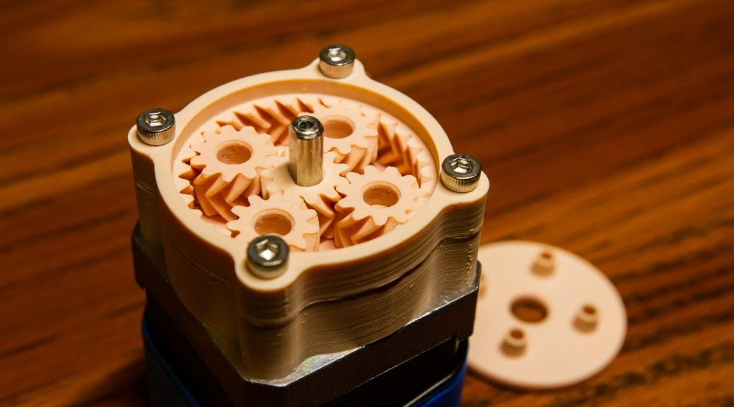 The engineer recognizes that assembling a gearbox is not an easy task, so he is available to answer questions from those who have encountered any difficulties in the process.
“Anyone who puts together one of my designs—a gearbox or an engine—will get a pretty good idea of how they actually work, because my models are exactly replicas of real mechanisms,” Harrell explains. “And it’s amazing because most people who are interested in 3D printing are unlikely to ever get the opportunity to actually recreate an engine or gearbox.” nine0003
Although most parts of the gearbox are 3D printed, some small parts cannot be printed on a personal 3D printer. We are talking about such details as a rod with a diameter of 3 mm, 628ZZ bearings, washers with a diameter of 3 mm and several other small elements that serve mainly for fasteners. At the same time, Harrell does not guarantee that all parts can be 3D printed in the correct scale - some of them may have to be adjusted to fit the rest of the structure.![]()


.jpg)