Multi part 3d printing
Multi-Part Printing | Simplify3D Software
In this tutorial, we will be teaching you everything you need to know about printing multiple parts at once on your 3D printer. Many new users focus on printing only one part at a time until they are happy with the results, but as you get more experienced you also have the option of importing multiple STL files into the software and printing them simultaneously. This can save a lot of setup and post-processing time. For example, imagine printing all 32 pieces of a chess set overnight and then coming back to an entirely finished game set in the morning. It would take a lot more work to print each piece one at a time.
The Simplify3D Software gives you a wide array of options for multi-part printing so that you can choose the best method for your specific needs. There are 3 different multi-part printing modes that we will be talking about.
- Single Process Printing Mode
- Multiple Process, Continuous Printing Mode
- Multiple Process, Sequential Printing Mode
The number of processes refers to the number of FFF processes that you will be configuring to control the print settings for your parts. The Simplify3D Software has the unique ability of allowing you to use different settings for each model you print. For example, if the King and Queen pieces in your chess set require different settings, you can easily configure this in the software and still print these parts simultaneously. This is one of the big advantages of the software and we will cover this in more detail later on.
Single Process Printing Mode
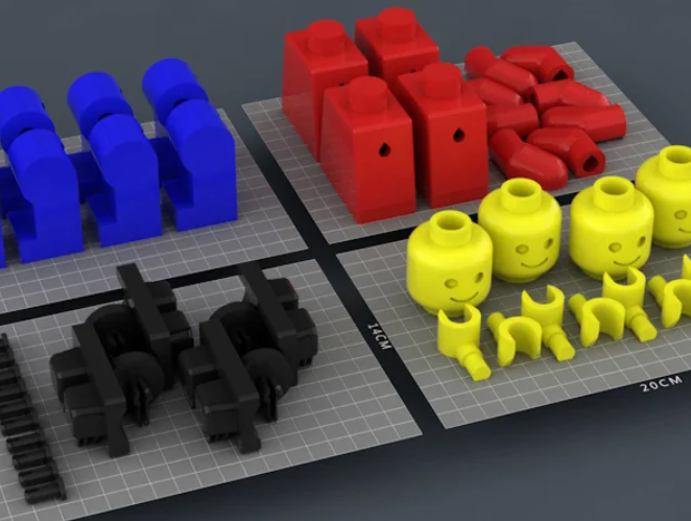
The first technique we will be covering is the single process printing mode. This is the easiest of all three methods and one that most users are probably already familiar with. This is the technique you would want to use if all of your parts use the exact same slicing settings and you don’t need the reliability and performance benefits that sequential printing offers. For example, you might be printing four identical LEGO bricks, like in the model found here. The models are small, simple, and you can arrange them close to one another to prevent excessive oozing while moving between parts. In this case, the single process printing mode is a great technique to use.
To begin, download and import the lego block STL file into the software. If you need to rename a model after importing, just double click on it to enter a new name. To make additional copies of this model, go to Models > Duplicate Selected Model. Make three identical copies and arrange them with a millimeter or two of spacing between them. Next, add a new FFF process and configure your slicing settings for the LEGO block models. In our case, we used medium quality, 60% infill. The last thing we need to do is select what models this specific FFF process will use. To do this, click the Select Models button in the bottom left of your FFF Settings. If we want to print all four pieces, make sure all four items are selected in the list or simply click the Select All button. Click Prepare to Print! to see the newly created printing instructions.
If you look at the G-Code preview, you should notice that the extruder prints all four pieces simultaneously. For each layer, the extruder prints one section of each block and then repeats this process. This results in a lot of movement back and forth between the different pieces, but as long as they are positioned fairly close together this should be okay.
Multiple Process, Continuous Printing Mode
For the next printing mode, we will be returning to the chess set example we described earlier. Go ahead and download the Knight and Pawn chess pieces. Import both of the STL files into the software and have a look at the features of the different models. You will notice that the pawn is very simplistic with gradual curves and features. The knight piece, on the other hand, has several fine detailed features such as eyes, hair, and teeth. It also has a fairly severe overhang on the chin of the model. In this case, it might be advantageous to use different slicing settings for these two models so that we can make sure they both print with the best quality possible.
As we learned in the previous section, we can use the Select Models button to determine what models a given FFF process uses. We could easily create one FFF process for the pawn and a second for the knight. That will give us more flexibility by letting us use the optimal settings for each model. First, let’s create the settings for the pawn. Create a new FFF process and call it “Pawn Process.” Use the Select Models button to make sure that this FFF process only applies to the pawn STL file. Now go ahead and configure the optimal settings for this model. We used 0.3mm layer heights with 3 outline perimeters and 0% infill. This will allow the part to print very quickly, which should be fine for the gradual rounded surfaces. If you want, you can Prepare and Preview this single process to make sure the pawn settings are configured properly.
Next, we will configure the settings for the knight. Add a new FFF process and call it the “Knight Process.” As before, use the Select Models button to make sure that this process only applies to the knight STL file. The settings for this part will be quite different than our pawn. We added support material for the chin overhang, used 0.15mm layer heights to help improve the quality of the fine features, and used 40% infill to help support the large flat surfaces at the top of the model. Save your settings and return to the main workspace.
The last thing we need to do is click the Prepare to Print! button to generate the printing instructions for our multiple FFF processes. The software will detect that you have multiple FFF processes and ask you which ones you want to merge together. Select both the “Pawn Process” and the “Knight Process.”
At the bottom of this window there is also an option to configure how these multiple processes will be combined. If we select the continuous printing mode, each process will be merged together, one layer after another. The result will look very similar to the single process printing mode that we described in the previous section, however, we now have optimized settings for each individual model.
Multiple Process, Sequential Printing Mode
The last printing mode we are going to talk about is sequential printing. This is a very useful printing mode that can help improve reliability and print quality, but you may need to re-arrange your models to use this technique. During sequential printing, the software will print multiple layers of a single model before transitioning to the next model. So it might print 30 layers of our pawn model before it moves over to the knight and prints 30 layers of it. This significantly reduces the amount of movement between models which results in a much cleaner surface finish. It also improves the reliability of the overall print since one model could actually separate from the build plate and fail without ruining the entire batch of parts. The image to the left illustrates the difference between the continuous (left) and sequential (right) printing modes. The thin red lines represent rapid movements where the nozzle is moving to a new location to begin printing.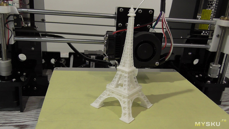 As you can see, the sequential printing mode results in much fewer movements between parts for faster and better looking prints.
So now that you know how sequential printing works, we need to check your hardware to determine how to re-arrange your parts. If the nozzle does not have sufficient clearance, your printer will end up colliding with one of the previously printed parts. The image to the left shows several common extruder configurations. Keep in mind that there may be external accessories such as fans or structural frames that reduce the available clearance of your extruder. The orange lines in the left image represent two parts being sequentially printed side-by-side. The spacing between these parts is an additional factor that determines if sequential printing would be successful. For example, the two bottom configurations do not have sufficient clearance with the current part spacing. However, if the spacing between the orange parts was doubled or tripled, the two bottom configurations would gain additional clearance.
To help illustrate this in more detail, let’s look at some real-world hardware. The Replicator 2 is a great example of how part spacing can affect your sequential printing clearance. The Replicator 2 blower fan sits right next to the extruder nozzle, which means that this printer has very little sequential printing clearance if the parts are arranged side-by-side and are only a few millimeters apart (see top image). However, if the part spacing is increased, the blower fan is no longer an issue and the X-axis rails become the new limiting factor (see bottom image). You could also arrange the parts so that one is positioned in front of the other, instead of side-by-side. As you can see, most printers will be able to use sequential printing, but it may require some extra planning and forethought to make sure the models are arranged in such a way to avoid any potential collisions.
Now that you have determined the best way to arrange your parts, the sequential printing setup process is very easy. You can follow the exact same steps outlined in the Multiple Process, Continuous Printing Section, however, we need to select a different option when we finally prepare our FFF processes. Instead of selecting the continuous printing mode when we choose what processes to prepare, we select the sequential printing option. This requires us to enter a value for the vertical clearance that was described above. For the Replicator 2 example, we have a measured clearance of 12mm, assuming the parts are far enough apart to avoid collisions with the blower fan. Enter the appropriate value for your printer and then press OK to create the combined G-Code file. If you followed these steps correctly, you can now enjoy better looking and more efficient multi-part prints!
We have now covered all of the multi-part printing modes available in the Simplify3D Software. Next time you have multiple parts to print, give these great time-saving techniques a try!
View the Complete Article Library
Multi Part best 3D printer models・Cults
Gorblinz Scrap Walkerz
€9. 41
41
Combination Square
Free
27 to 1 reduction gearset
Free
R. Maker - Mark I
Free
Simple multi-part Toy Train
€9.41 -50% €4.71
Green-Skin Mini Scrap Buggy v1
€4.71
Screwless Heart Gears
Free
Screwless Cube Gears
Free
Cube Gears
Free
Kunai Naruto Iman Multipart
€2.71
Multi config 3D printer toolbox
Free
Goblinz Scrap Tank V2 Set 1
€14. 12
12
The coffee mouse
€6
The Chaos Machine
€2.76
RAF Logo (75mm)
Free
The Sushi Dragon
€6.29
Christmas Wreath
Free
'ROCKETZ'... Interlocking Storage Stages and Fun Model
Free
Mars Exploration Rover
Free
Bauble
Free
Pinecone decor lamp
Free
The HIVE - Modular Hex Drawers
Free
Gnome Gears
Free
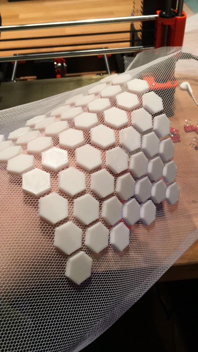
Hand Wing
Free
multicolored snowman bauble
€0. 75
75
Lego Zombie Minecraft Multi-extrusion
Free
March for Science DNA Logo
Free
7-Eleven Logo #7ElevenDay
€0.63
3-in-1 Beginner/Intermediate/Expert Rock Climbing Grip
Free
Sun and moon container
Free
Spongebob multi colour figure
Free
snowman_V3 multipart
€1.25
snowman cookie jar
€1.25
Multi material Knife
Free
Car Headrest Bag Hooks
Free
Corner Drawers
Free
Capsules
Free
A 'Bright' Idea'.
 ..
..Free
Spinning Stand
Free
Ghosts in the Window (or Wall)
Free
ORBZ - A mutli-layerd orb shaped storage solution
Free
Trimaran
Free
The "Revolver" - One Colour Print version of this Challenging Revolving Puzzle
Free
The "Revolver"... easy to print but challenging to solve!
Free
Plumbus multi-part model
Free
Printable V8 motor
Free
Luci - Disenchantment (multi-material)
Free
Seattle Space Needle
Free
Multi-color 3D printing with one extruder, in one layer
3D printing
extruder.

As usual, by creating new problems. :)
The material is difficult, not everyone can handle it.
Short video describing the method here:
First, I will talk about the traditional method of multi-color printing with a single extruder, as well as its advantages and disadvantages.
The traditional printing method allows you to create multi-color printouts by replacing plastic of one color with plastic of a different color after printing a certain layer of a part.
i.e. each layer of a different color is stacked on top of the previous layers.
Everyone does it and doesn't seem to complain, it's a quick and easy to implement method to create color prints with a single extruder. nine0003
However, the method creates a number of problems (which, of course, I invented myself and rushed to solve it myself :D): Each new color forces us to increase the thickness of the part, creating a relief that is not always necessary.
There may be other problems not mentioned by me, you can describe them in the comments.
Solution:
The solution is not simple, and will require a special approach already at the design stage of the model, and editing the G-code. As I said above, not everyone can do it. The solution is still limited to flat parts, but allows you to use any adequate number of colors and materials in the project. nine0003
So let's get started:
Step 1: Modeling
Each layer of the new color should be placed above the previous layer.
Literally - when modeling, place layers of different colors on top of each other, so that they seem to be inserted into each other, without intersecting with each other. Look at the finished model, it should be clearer.
Free space can be provided by cutting the bottom layer in the shape of the overlying layers, or by creating a relief, as in traditional printing. nine0003
Contours of different colors must not intersect.
Step 2: Slicing
Slicing is carried out as usual
Step 3: Editing the G-code
Editing the code is to fool the printer at a certain point and make it lower the overlying layer to the print height of the previous one. Thus, combining two or more layers in one, with the subsequent replacement of the filament.
This is done by inserting into the code, before a layer of a different color, the following commands:
- G92 ZHeightReplacementLayer
- M600 - or similar script for replacing plastic
For example:
to change the plastic and print two colors in one layer, we must insert the code
- G92 Z0.
 4 - making the printer think that it has already raised the extruder to a height of 0.4 mm
 - M600 - to replace the plastic. nine0036
As a result of executing these commands, the black layer will be printed at the same height as the white layer - i.e. 0.2 mm.
And that's all for me, I wish everyone successful printouts. To be continued.
Copper 3D Printing - Complete Guide
Copper is one of the newest and most promising areas of metal 3D printing for everything from electric motors to heat sinks.
Previously, copper 3D printing was a challenge due to the metal's reflectivity and high thermal conductivity, but advances in printers and materials have largely resolved these early problems. Today, 3D printed copper propulsion systems send rockets into space, 3D printed copper heatsinks cool processors, and 3D printed copper coils boost the performance of electric motors. nine0003
3D printed copper parts (Source: Trumpf)
Why 3D print copper?
Copper has always been a very useful metal due to its ability to conduct heat and electricity, resist corrosion and even kill bacteria and viruses. Demand for complex copper parts is on the rise as 3D printing opens up even more uses and possibilities for this metal.
3D printing (also known as additive manufacturing) allows the creation of exceptionally complex shapes, fine details, internal structures and lattice inserts that are not possible with any other form of metal fabrication. These capabilities reduce weight, increase efficiency, and reduce fabrication and assembly times, as multi-component assemblies can be 3D printed as a single unit. nine0003
Additive metallurgy
3D printing also allows this relatively expensive metal to be produced more efficiently, reducing waste by using only the amount of material needed to make each part. For companies interested in copper 3D printing, reducing raw material costs is critical.
If you already produce custom copper parts, 3D printing can significantly reduce your production costs while optimizing part performance. nine0003
Markforged 3D printed copper heatsink (Source: Markforged)
Although there aren't many 3D printers that can print copper, there is still a wide variety of printing technologies and prices.
FDM printers using copper-filled plastic filament can produce copper jewelry, decorative items, and other parts that are almost 100% copper. While for more advanced production, 3D printers using copper powder, rods or copper polymer slurry produce industrial parts with excellent mechanical and conductive properties, which can meet international standards such as IACS (International Annealed Copper Standard). nine0003
Let's look at what types of printers can work with copper today. Trumpf TruPrint 1000 Green Edition 3D Printer several equipment manufacturers have recently included copper in their material list. Since copper is highly reflective, laser processing of the powder has been a hurdle for manufacturers. However, this technology and materials have evolved to solve this problem. nine0003
3D printer manufacturer Trumpf, for example, has developed an industrial green laser that can 3D print materials such as copper, copper alloys, and precious metals that are difficult to process with infrared waves.
Two powder layer technologies for metal 3D printing, DMLS (Direct Metal Laser Sintering) and EBM (Electron Beam Melting), work by depositing a thin layer of copper powder onto a platform inside the printer. The powder heats up while lasers or electron beams draw the first layer of the part. When the particles in the layer fuse, the platform is lowered slightly into the assembly chamber, and fresh powder is poured on top, and the process is repeated. Some of the copper powder left over from the process can be recycled for use in the next print. nine0003
Copper additive manufacturing powder from GNK Powder Metallurgy (Source: GNK)
Copper-bonded 3D inkjet printers
Copper powder bonded with a liquid binder and sintered in a furnace is a 3D printing technique known as binder inkjet printing that allows parts to be obtained without the use of an auxiliary material. Bond jetting is a no-heat process in which a bonding layer is sprayed between each layer of metal; the binder is then removed during the sintering process. nine0003
Binder blasting is a popular additive manufacturing method for high volume metal parts.
Featured image of
Copper parts printed on Markforged0's Metal X printed copper parts
The most economical approach to 3D printing copper parts is to use machines that extrude the filament. Metal filament for printing metal parts consists of a plastic base with metal particles evenly interspersed in it. Copper interspersed filament for copper parts is a unique type of composite filament that, when used correctly, produces strong, chemically resistant, and near-solid metal parts. nine0003
Virtually any Fused Deposition Modeling (FDM) printer can print near-solid metal parts using a polymer filament filled with copper powder. Currently, there is only one option on the market - from the manufacturer of threads The Virtual Foundry. The company claims that its copper filament is suitable for printing on any filament 3D printer with a hardened nozzle and a hot end that can reach temperatures of up to 225ºC.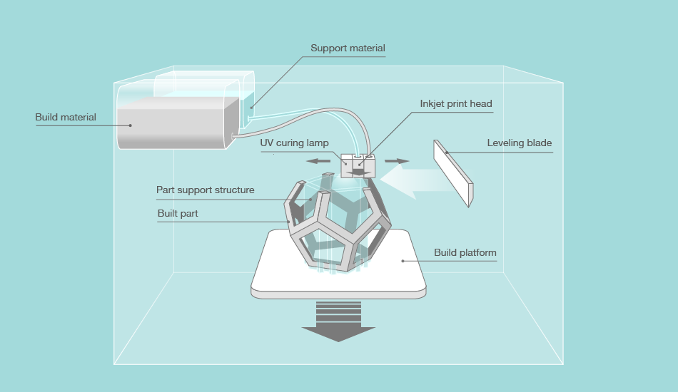 However, the parts do not become metal immediately after printing and require additional post-printing steps to melt the resin binder and leave only the metal. nine0003
Other types of copper thread contain enough real copper particles to be polished and given a metal-like weight, but are for decorative purposes.
A company in Chile called Copper3D produces a copper-filled filament that produces parts that do not have metal parts, but parts that have the antibacterial and antimicrobial properties of copper. NASA is even testing the filament for use in "interplanetary microbial contamination," according to the company. nine0003
In addition to the mainstream FDM printers, two other filament-extruding printers also offer copper, but they use their own proprietary materials. Desktop Metal uses a bonded metal filament, while Markforged uses a similar metal powder bonded into a plastic matrix. The printers from these manufacturers produce all-metal parts designed for industrial use, such as machine tools, induction coils, heat sinks, and functional prototypes. nine0003
Copper Cold Spray and DED 3D Printers
WarpSpee3D Cold Spray 3D Printer (Source: Spee3D)
Although these two metal 3D printing methods are not usually combined together here due to their general application for coating metal parts with another metal and for layering metal parts with metal powder.
Directed Energy Deposition (DED) is a system developed by Optomec of New Mexico to create, improve and repair metal parts. Like SLS, in DED, high-power lasers build up 3D structures in layers, creating parts with high density and strength, ideal for mechanical applications. In 2019Optomec developed a new copper DED process to produce heat exchangers for use in the aerospace, chemical and other industries.
Spee3D's WarpSpee3D process is unique in its use of supersonic 3D deposition to produce parts from a range of metal powder materials, including copper and aluminum.
Cold spray is an additive manufacturing technique in which metal powder is injected into a supersonic pressurized gas stream. Instead of melting the metal, cold spraying holds it together in a process called plastic deformation. Companies such as Spee3D are using cold spray technology to apply an antimicrobial copper coating to doors, handrails and touch panels intended for use in hospitals, schools and other public places. nine0003
Cold spray is also the fastest metal 3D printing method. Spee3D printed a 17.9kg (17.9kg) pure copper aerospace rocket nozzle lining (pictured below) on WarpSpee3D in about three hours at a cost of just $716, according to the company. Parts like this are usually made from solid forged copper, which takes weeks and costs tens of thousands of dollars.
One of the disadvantages of DED and cold spray is that they are limited in the production of complex geometries. nine0003
Rocket nozzle copper plating, engineer's spark-free copper hammer and copper cable clamp, 3D printed by Spee3D (Source: Spee3D)
Photopolymerization
Holo)
Metal DLP 3D printing is similar to resin 3D printing in that it uses UV light projected onto a photosensitive slurry to cure layer by layer.