Marlin firmware for 3d printer
Download | Marlin Firmware
Previous releases can be downloaded directly from the Marlin Github page.
| Description | Version | Download | Configurations |
|---|---|---|---|
| Current Marlin Release Supports AVR and ARM Arduino and PlatformIO | 2.1.2 | 2.1.2.zip | View / Download |
| Marlin 2.0 LTS Supports AVR and ARM Arduino and PlatformIO | 2.0.9.5 | 2.0.9.5.zip | View / Download |
| Marlin 1.1 LTS Supports AVR Arduino and PlatformIO | 1.1.9.1 | 1.1.9.1.zip | View / Download |
| Marlin 1.0 LTS Supports Arduino 1.6.8 and up | 1.0.2-3 | 1.0.2-3.zip | (included) |
Marlin "Nightly" Source
| Description | Version | Download | Configurations |
|---|---|---|---|
| ⚠️ Work in progress - Updates for 2. 2.1.x "bugfix" snapshot Supports AVR and ARM Arduino and PlatformIO | bugfix-2.1.x | bugfix-2.1.x.zip | View / Download |
| ⚠️ Work in progress - Updates for 2.0.x 2.0.x "bugfix" snapshot Supports AVR and ARM Arduino and PlatformIO | bugfix-2.0.x | bugfix-2.0.x.zip | View / Download |
| ⚠️ Work in progress - Updates for 1.1.x 1.1.x "bugfix" snapshot Supports Arduino 1.6.8 and up | bugfix-1.1.x | bugfix-1.1.x.zip | View / Download |
Marlin Patched Source
| Description | Version | Download | Configurations |
|---|---|---|---|
| Latest 2.1.x with Hotfixes Marlin 2.  1.2 with bug fixes 1.2 with bug fixesSupports AVR and ARM Arduino and PlatformIO | 2.1.x | 2.1.x.zip | View / Download |
| Latest 2.0.x with Hotfixes Marlin 2.0 with bug fixes Supports AVR and ARM Arduino and PlatformIO | 2.0.x | 2.0.x.zip | View / Download |
| Latest 1.1.x with Hotfixes Marlin 1.1 with bug fixes Supports Arduino 1.6.8 and up | 1.1.x | 1.1.x.zip | View / Download |
Also find on the project page…
- Detailed release notes,
- Resources for reporting issues, and
- The tools needed to join the project.
What is Marlin? | Marlin Firmware
Marlin is an open source firmware for the RepRap family of replicating rapid prototypers — popularly known as “3D printers. ” It was derived from Sprinter and grbl, and became a standalone open source project on August 12, 2011 with its Github release. Marlin is licensed under the GPLv3 and is free for all applications.
From the start Marlin was built by and for RepRap enthusiasts to be a straightforward, reliable, and adaptable printer driver that “just works.” As a testament to its quality, Marlin is used by several respected commercial 3D printers. LulzBot, Průša Research, Creality3D, BIQU, Geeetech, and Ultimaker are just a few of the vendors who ship a variant of Marlin. Marlin is also capable of driving CNC machines and laser engravers.
One key to Marlin’s popularity is that it runs on inexpensive 8-bit Atmel AVR micro-controllers - Marlin 2.x has added support for 32-bit boards. These chips are at the center of the popular open source Arduino/Genuino platform. The reference platforms for Marlin is an Arduino Mega2560 with RAMPS 1.4 and Re-Arm with Ramps 1.4.
As a community product, Marlin aims to be adaptable to as many boards and configurations as possible. We want it to be configurable, customizable, extensible, and economical for hobbyists and vendors alike. A Marlin build can be very small, for use on a headless printer with only modest hardware. Features are enabled as-needed to adapt Marlin to added components.
Main features
- Full-featured G-code with over 150 commands
- Complete G-code movement suite, including lines, arcs, and Bézier curves
- Smart motion system with lookahead, interrupt-based movement, linear acceleration
- Support for Cartesian, Delta, SCARA, and Core/H-Bot kinematics
- Closed-loop PID heater control with auto-tuning, thermal protection, safety cutoff
- Support for up to 5 extruders plus a heated printbed
- LCD Controller UI with more than 30 language translations
- Host-based and SD Card printing with autostart
- Bed Leveling Compensation — with or without a bed probe
- Linear Advance for pressure-based extrusion
- Support for Volumetric extrusion
- Support for mixing and multi-extruders (Cyclops, Chimera, Diamond)
- Support for Filament Runout/Width Sensors
- Print Job Timer and Print Counter
How Marlin Works
Marlin Firmware runs on the 3D printer’s main board, managing all the real-time activities of the machine. It coordinates the heaters, steppers, sensors, lights, LCD display, buttons, and everything else involved in the 3D printing process.
Marlin implements an additive manufacturing process called Fused Deposition Modeling (FDM) — aka Fused Filament Fabrication (FFF). In this process a motor pushes plastic filament through a hot nozzle that melts and extrudes the material while the nozzle is moved under computer control. After several minutes (or many hours) of laying down thin layers of plastic, the result is a physical object.
The control-language for Marlin is a derivative of G-code. G-code commands tell a machine to do simple things like “set heater 1 to 180°,” or “move to XY at speed F.” To print a model with Marlin, it must be converted to G-code using a program called a “slicer.” Since every printer is different, you won’t find G-code files for download; you’ll need to slice them yourself.
As Marlin receives movement commands it adds them to a movement queue to be executed in the order received.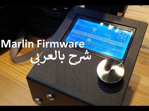 The “stepper interrupt” processes the queue, converting linear movements into precisely-timed electronic pulses to the stepper motors. Even at modest speeds Marlin needs to generate thousands of stepper pulses every second. (e.g., 80 steps-per-mm * 50mm/s = 4000 steps-per-second!) Since CPU speed limits how fast the machine can move, we’re always looking for new ways to optimize the stepper interrupt!
Heaters and sensors are managed in a second interrupt that executes at much slower speed, while the main loop handles command processing, updating the display, and controller events. For safety reasons, Marlin will actually reboot if the CPU gets too overloaded to read the sensors.
Printing Things
Modeling
While Marlin only prints G-code, most slicers only slice STL files.
Whatever you use for your CAD toolchain, as long as you can export a solid model, a slicer can “slice” it into G-code, and Marlin firmware will do its best to print the final result.
Before Marlin can dream of printing, first you’ll need a 3D model. You can either download models or make your own with one of many free CAD programs, such as FreeCAD, OpenSCAD, Tinkercad, Autodesk Fusion 360, SketchUp, etc.
A high degree of knowledge is needed to model complex objects like a T-Rex Skull, but other objects can be quite simple to model. To get ideas and test things out, explore sites like Thingiverse, YouMagine and Printables and print things for fun.
Slicing
Slicers prepare a solid 3D model by dividing it up into thin slices (layers). In the process it generates the G-code that tells the printer in minute detail how to reproduce the model. There are many slicers to choose from, including:
- Cura.
- Slic3r.
- PrůšaSlicer (formerly Slic3r Průša Edition) The new Kid on the block based on Slic3r.
- Simplify3D is a commercial offering.
Printing
Marlin can be controlled entirely from a host or in standalone mode from an SD Card. Even without an LCD controller, a standalone SD print can still be initiated from a host, so your computer can be untethered from the printer.
Host software is available for several platforms, including desktop systems, Raspberry Pi, and Android tablets. Any device with a USB port and serial terminal can technically act as a host, but you’ll have a better printing experience using host software specifically designed for 3D printers. Current selections include:
- Pronterface is an open source host by Kliment.
- Repetier Host is a closed-source host by Repetier Software.
- OctoPrint is an open source host for Raspberry Pi by Gina Häußge.
- Cura is an open source host by Ultimaker. (WARNING: You can no longer manual select com port and speed, your printer needs to be auto detected by Cura)
- Simplify3D includes both a host and slicer.
Many 3D printers ship with a customized version of Repetier or Cura. While this helps to associate the printer brand with a companion piece of software, these versions are usually obsolete and receive few upgrades.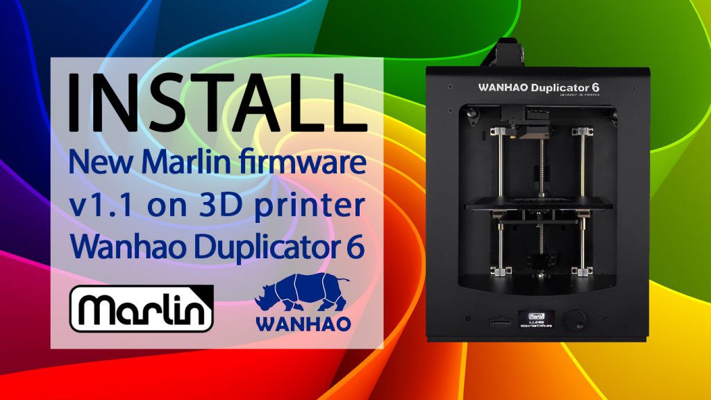 We recommend you download the latest generic version of your preferred host software instead.
Set up the Marlin firmware and upload it to the 3D printer
Many 3D printers run the popular firmware Marlin . The firmware is pre-configured for Ultimaker Original. Let's analyze the basic settings for other 3D printers.
The firmware is located at this address. Downloading. We press the button Download ZIP . The archive Marlin-Development.zip is downloaded. Unpack it to the selected folder.
Now downloading Arduino IDE to patch and upload firmware to 3D printer . Link. We press on Windows Installer . Installer arduino-1.6.0-windows.exe is downloaded. We launch it and install the environment Arduino IDE .
Go to the firmware folder and run the file Marlin.ino .
Opens Arduino IDE with firmware. We need a tab Configuration.h .
At the beginning we see references to calibration 3D printer . Scroll further and read: ' This is a configuration file with basic settings. Select controller type, temperature sensor type, calibrate axis movements and configure limit switches.'
Let's start with controller selection (MOTHERBOARD). The list of controllers is in the tab boards.h . Click on the triangle in the upper right corner and select boards.h .
Now look at the installed electronics. Here are some board types:
Melzi
RAMPS 1.4
I have RAMPS 1.4.
Replace in configuration.h 'MOTHERBOARD BOARD_ULTIMAKER' with 'MOTHERBOARD BOARD_RAMPS_13_EFB'.
#ifndef MOTHERBOARD
#define MOTHERBOARD BOARD_RAMPS_13_EFB
#endif
Next select temperature sensor - thermistor . We see a large list of '//// Temperature sensor settings:'. I have an E3D-v5 hotend and a Chinese thermistor on the table. For E3D-v5 I choose '// 5 is 100K thermistor - ATC Semitec 104GT-2', for the table '// 1 is 100k thermistor - best choice for EPCOS 100k'. If the type of thermistor is unknown, you can choose 1, and if you don’t like the temperature, you can choose any and test. I change.
100K thermistor - ATC Semitec 104GT-2
Ordinary Chinese thermistor 100K
Hotend maximum temperature limit '#define HEATER_0_MAXTEMP 275'.
Hotend minimum temperature limit '#define EXTRUDE_MINTEMP 170'.
If the limit switch is not connected to the standard and its state needs to be inverted , then this can be done in the firmware without soldering the wires. Values false or true . The command M119 (for example in Pronterface ) shows the state of the limit switches. My limit switches are only in position HOME on MAX .
In position HOME
In position different from HOME on all axes
I did not need to change anything.
const bool X_MIN_ENDSTOP_INVERTING = true;
const bool Y_MIN_ENDSTOP_INVERTING = true;
const bool Z_MIN_ENDSTOP_INVERTING = true;
const bool X_MAX_ENDSTOP_INVERTING = true;
const bool Y_MAX_ENDSTOP_INVERTING = true;
const bool Z_MAX_ENDSTOP_INVERTING = true;
Change the direction of rotation of stepper motors , values false or true . Correct movements of the nozzle relative to the table :
- Along the X axis - to the left '-', to the right '+'.
- Y - forward '+', backward '-'.
- Z-axis - approach '-', removal '+'.
- Extruder. Extrude - thread extrusion, Reverse (retract) - rollback, thread retraction.
#define INVERT_X_DIR false
#define INVERT_Y_DIR false
#define INVERT_Z_DIR false
#define INVERT_E0_DIR true
Next comes setting limit switches 4.9000 We need to find out where they are located . How to find out? The origin is in the near left corner on the table surface , if the nozzle is brought to this point, then the limit switches MIN would work, if to the far upper right, MAX would work. I have three limit switches MAX at position HOME , so my settings are
// Sets direction of endstops when homing; 1=MAX, -1=MIN
#define X_HOME_DIR 1
#define Y_HOME_DIR 1
#define Z_HOME_DIR 1
Setting travel dimensions , after initialization at position HOME . Here we set the dimensions of the working area in X and Y, as well as the setting of the nozzle relative to the table.
If when the nozzle touches the table, the limit switch is triggered ( MIN ), as in Ultimaker Original, then the nozzle is adjusted relative to the table by moving the limit switch, and in '#define Z_MAX_POS' we write the coordinate value at the maximum distance of the nozzle from the table. The coordinate can be found by command M114 or by looking at the display screen.
If the Z limit switch is activated at the maximum distance of the nozzle from the table ( MAX ), then you need to find the Z dimension yourself. Set the value '#define Z_MAX_POS' to be initially higher than the norm, for example 250 with a dimension of 200 mm. We lower the nozzle until it touches the table and on the display (or by command M114 ) we see a coordinate greater than zero, now subtract the obtained coordinate from the set large value and get the Z dimension, which we will now write in '#define Z_MAX_POS'. Based on the results of printing the first layer, this value can be corrected. . The extruder is also an axis. My settings.
Now let's see how I got them . All axes are equipped with stepper motors 200 steps per revolution, 16 micro steps per step (set by jumpers on the board). Along the X and Y axes there is a GT2 drive belt with a 2 mm pitch and 20 teeth pulleys , in total we get the formula (200 * 16) / (2.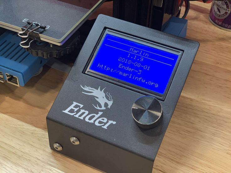 0 * 20). Along the Z axis there are M8 studs with a thread pitch of 1.25 mm, the total formula is 200 * 16 / 1.25.
We find specifications (datasheet) for installed stepper motors . We see that in one step the shaft rotates 1.8 degrees, which means 360 / 1.8 = 200 steps per full turn. This parameter is the same for most stepper motors installed in home 3D printers.
Belt profiles commonly used on 3D printers and their step . Original here, page 61.
Pulley
How to measure screw pitch ? We measure the section of the screw and count the turns on it, then divide the length of the section in millimeters by the number of turns 20/16 = 1.25 mm. For a more accurate result, we measure the section of maximum length.
The setting of the extruder depends on the reduction ratio and the feed gear diameter. We will select experimentally , after the first firmware upload to 3D printer . Unscrew the nozzle and reduce the minimum nozzle temperature limit to 5 degrees '#define EXTRUDE_MINTEMP 5'. Now the extruder will work with a cold nozzle, which is what we need. We do not change the extruder settings yet. For configuration, I use the Pronterface program. To begin with, we set 50 mm and the speed is 100 mm / s. 50mm is the length of the bar that goes through the extruder. We measure the length of the rod passed through the extruder with a ruler or caliper.
Selecting the extruder setting, we achieve an exact figure on a reasonable length of the rod, for example 300 mm. After setting , we will return the minimum temperature limits '#define EXTRUDE_MINTEMP 170'.
The following digits are the maximum travel speed limit for the axes . On X and Y I put 200 mm, I don’t touch the rest.
#define DEFAULT_MAX_FEEDRATE {200, 200, 5, 25}
Axis acceleration setting . At high accelerations steps may be skipped . You can pick it up by driving in the Pronterface program along the axes at a given speed. Here are my settings:
#define DEFAULT_MAX_ACCELERATION {1000,1000,100,10000}
#define DEFAULT_ACCELERATION 1500
It remains to activate LCD with SD card . I found my display on RepRap.org and identified it as RepRapDiscount Smart Controller .
Uncomment (remove double slashes) the following lines:
#define ULTRA_LCD
#define SDSUPPORT
#define ULTIPANEL
#define REPRAP_DISCOUNT_SMART_CONTROLLER
There is another tweak to improve the accuracy of operation of some limit switches. When setting zero in Z, I encountered the fact that after each initialization of HOME , the position of the nozzle above the table changed slightly. Digging through the firmware, I found a parameter responsible for initializing the limit switches.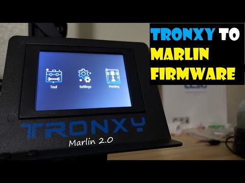 Go to tab Configuration_adv.h and look for the line '#define Z_HOME_RETRACT_MM 2', change the value 2 to 5 and don't remember this parameter anymore.
It's time to upload the firmware to the controller. To do this, you need to correctly set the type of board and the number COM of the port in Arduino IDE . The card type and port number will be displayed at the bottom of the window. Don't forget to save changes (Ctrl+S) .
RAMPS
MELZI
0003 Arduino IDE you need to copy and replace all from the firmware folder 'Marlin-DevelopmentArduinoAddonsArduino_1.5.xhardwaremarlinavr' to the Arduino IDE folder 'C:Program Files (x86)Arduinohardwarearduinoavr'. After that, it becomes possible to select the board Sanguino (base board for Melzi ) and the desired type of processor . I don't have a Melzi board so I can't check.
For fill firmware click on the circle with an arrow.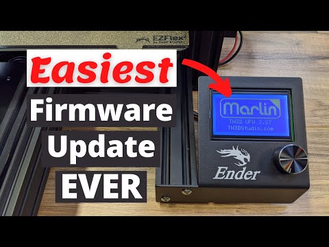
The progress of uploading the firmware is displayed by the indicator
For this I use Pronterface . We enter the command ' M303 E0 C8 S260 '. Where M303 is the calibration command, E0 is the hot end, C8 is the number of heating-cooling cycles, S260 is the typical operating temperature of the nozzle.
Last results are written to firmware .
#define DEFAULT_Kp 12.22
#define DEFAULT_Ki 0.58
#define DEFAULT_Kd 64.08
Using the same scheme , we calibrate the PID of table . Command ' M303 E-1 C8 S110 '. Where E-1 is the table, S110 is the typical table heating temperature. The last results are written to firmware . My table heats up very slowly and therefore I have to restart the command due to a Timeout error.
#define DEFAULT_bedKp 105. 94
94
#define DEFAULT_bedKi 4.97
#define DEFAULT_bedKd 564.11
The parameters set in the firmware can be found in the program Repetier-Host through the menu ConfigurationConfiguration EEPROM . You must first specify COM port in the settings and click the button ' Connect '.
When connecting a 3D printer to program Pronterface list of firmware parameters is displayed on the right side of the window
Also parameters can be seen on LCD display Via menu ControlMotion .
Would love to see similar instructions for Delta printers, CoreXY and H-Bot 3D printers.
Criticisms are highly welcome as the instructions will be posted on the 3D Wiki later on. The opinion of beginners is also very important, since all this is done just for you!
Installing Marlin firmware on 3D printer using Cura slicer or what to do with hex file?
Hello everyone. This article is the second part of a trilogy about 3D printer firmware. In the first part, we looked at how to flash a 3D printer using the Arduino IDE. This method is possible when there is a source code for the firmware or, as programmers say, when there are sources. However, this option is not always possible, because. often the firmware comes in an already compiled form, i.e. as a single file with *.hex extension. This is a ready-made compiled firmware file with pre-configured parameters. At the same time, it becomes impossible to edit anything.
Naturally, this file cannot be opened using the Arduino IDE. What to do? This is what we will deal with in this article. And so, let's figure it out.
On the one hand, firmware in the form of source code is good. We can easily independently make the necessary changes to it, or, so to speak, customize it for ourselves.
From the manufacturer's point of view, firmware source code is evil. The user will pick it up, make changes that are not provided by the manufacturer, and then apply for a guarantee if something goes wrong.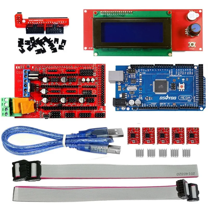 There are ways in which you can flash the firmware into the printer once and for all, while eliminating the possibility of flashing. Thank God manufacturers don't do that.
You can protect the firmware from modifications in another way - by supplying it as a ready-made firmware file. Let it not always go with the observance of the license. But this option works just fine.
We, as ordinary customers, are not interested in all these twists and turns. We have another question: How to flash a 3D printer with a ready-made firmware file?
Do not believe it, but this option is much easier than flashing the printer from the firmware sources (the process of flashing the printer from the sources is described in the article “Installing Marlin firmware on a 3D printer using the Arduino IDE“). There are several ways to flash a 3D printer using a hex file. In my opinion, the easiest way is flashing with the Cura slicer. We will consider this method next.
The technique is described using the Cura 4. 2.1 slicer as an example.
We need a Cura slicer
And the actual firmware file.
Now turn on your 3D printer and connect it to your computer with a cable.
Check that the slicer can see your printer.
Now start the slicer and go to your printer's Menu. To do this, go to the menu item “ Parameters ” -> “ Printer ” -> “ Printer management ”
If you have several printers, select the one you want to flash from the list.
Once selected, a menu with several buttons will be available on the right, among which there will be a button labeled “Update Firmware”. Click on this button.
This will open a window named “ Update Firmware ”. In this window, press the button “ Upload your own firmware ”.
Now the Cura slicer will ask you to select the firmware file you will be slicing. The explorer menu will open. We go to the directory in which the firmware file lies and select this file.
In my case, it was the firmware for the Anycubic 4max 3D printer. In your case, this should be the firmware you want to flash. After selecting the firmware file, you must press the button “ Open ”
After clicking the “Open” button, the process of flashing your 3D printer will automatically start. And it will last for some time.
After the firmware is finished, the window will look like this:
Button “ Close ” becomes active. To complete the flashing process, press the button “ Close “.
Click the “ Close ” button in the “ Upgrade Firmware” window.
Click the “ Close ” button in the “ Settings” window of the “ Printers” section.
Now close the slicer.
Restart your 3D printer. To do this, unplug it from the outlet for 1-2 minutes and turn it on again.
Via printer menu or command.
To reset the printer settings to default, execute the following commands:
M502
M500
The process of sending commands to the 3D printer was described in the article “3D Printer's Diary. Calibration of the plastic feed on the extruder MK8 of the Anycubic 4max 3D printer
At this point, the process of flashing the 3D printer can be considered complete.
I hope the article was useful to you. For those who are interested, an article will soon be published on how to compile the firmware hex file yourself.
If you have not got a 3D printer yet and are thinking about which model to choose, I can recommend the following models:
Anycubic i3 Mega 3D printer
Anycubic Mega-S (Anycubic S) 3D printer liked the article and you want to support the site, receive notifications of new materials, join our Vkontakte group: https://vk.