Marlin 3d printer calibration
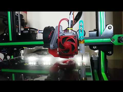
3D Printer - Extruder Calibration
The instructions below are meant to be a guideline for calibrating your extruder. Because every machine is slightly different, it is recommended to also reference your manual during the process. Also, the steps below assume that you have a machine that is running Marlin firmware which is what most consumer 3D printers come with.
Prerequisites:
- Running Marlin Firmware
- Machine connected to pronterface or another machine control software (YouTube Tutorial)
- EEPROM is enabled on your machine which allows changes to be saved to your printer (YouTube Tutorial)
Your extruder is responsible for feeding filament through the hotend. It is important that your extruder is accurate with how much material it is feeding to the hotend. If it is extruding too little filament then you will end up with under extrusion which will cause gaps and holes in your print. If your extruder is feeding too much filament, you will get over extrusion which can lead to poor overhand performance and bad print quality overall.
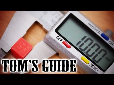
Step 1: Load filament into your extruder and mark a line 110mm from the spot it in enters the extruder. Please note the image below is a metric tape measure. 11cm = 110mm
Step 2: Send M503 to your machine using pronterface (or similar) to get the current E Step value. You should see M92 followed by a value that starts with E (Be sure to write this number down). Please note your value will likely be different than mine.
Step 3: Send M83 (Relative Mode, nothing should happen)
Step 4: Send M109 S200 (preheats the hotend to 200 degrees C for PLA. If using another filament substitute that temperature here)
**Do not continue until hotend temperature is reached**
Step 5: send G1 E100 F100 (This will feed 100mm of filament through the extruder)
Step 6: Measure the new distance from your reference point to the mark you originally made on the filament. Ideally, this should measure 10mm if your machine is already calibrated. Likely, however, you machine will require some calibration. Calculate the new E-Step value using the formula below:
Dislike Math? Use our free EStep Calculator:
Step 7: Update the machine with the new E-Steps calculated by sending M92 E(new e-step value)
Example: M92 E426
Step 8: Send M500 (stores new values in EEPROM)
Step 9: You can repeat this process over again to verify your results. Ideally, your measurement should be 10mm after extruding. If you find your measurements are inconsistent, your extruder may be slipping and adjustment might be necessary.
Step 10: Next, we recommend following our guide on Flow Rate Calibration
Back to ArticlesUse left/right arrows to navigate the slideshow or swipe left/right if using a mobile device
Linear Advance Calibration Pattern | Marlin Firmware
Use this form to generate G-code that you can use to calibrate your Linear Advance K-factor.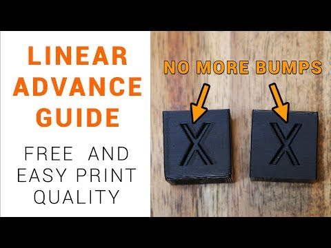 Default values apply to standard PLA with a 0.4mm nozzle.
Press the Generate G-code button followed by Download as file to save the result.
Settings | G-code | ||
Printer Info | |||
| Printer Name | |||
|---|---|---|---|
| Filament | |||
| Filament Diameter | Diameter of the used filament (mm) | ||
| Nozzle Diameter | Diameter of the nozzle (mm) | ||
| Nozzle Temperature | Nozzle Temperature (°C) | ||
| Bed Temperature | Bed Temperature (°C) | ||
| Retraction Distance | Retraction distance (mm) | ||
| Layer Height | Layer Height (mm) | ||
| Extruder | Extruder Index (0...) | ||
| Fan Speed | Fan Speed (%) | ||
Print Bed | |||
| Bed Shape | RectangularRound | Rectangular or round bed.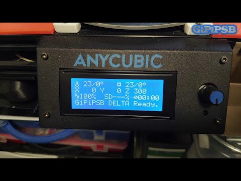 2) 2) | |
| Jerk X | Set the Jerk for the X-axis. -1 to use firmware default | ||
| Jerk Y | Set the Jerk for the Y-axis. -1 to use firmware default | ||
| Jerk Z | Set the Jerk for the Z-axis. -1 to use firmware default | ||
| Jerk E | Set the Jerk for the Extruder. -1 to use firmware default | ||
Pattern | |||
| Lin Advance Version | 1.01.5 | Select version 1.0 for Marlin 1.1.8 and earlier. Select 1.5 for Marlin 1.1.9 / 2.0 and up | |
| Pattern Type | StandardAlternate | Select standard or alternate pattern | |
| Starting Value for K | Starting value for the K-factor | ||
| Ending Value for K | Ending value of the K-factor | ||
| K-factor Stepping | Stepping of the K-factor in the test pattern. Needs to be an exact divisor of the K-factor Range (End - Start) | ||
| Slow Speed Length | Length of the Slow Speed test-line (mm) | ||
| Fast Speed Length | Length of the Fast Speed test-line (mm) | ||
| Test Line Spacing | Distance between the test lines. This will impact print size This will impact print size | ||
| Print Anchor Frame | Adds a frame around the start and end points of the test lines. May improve adhesion | ||
| Printing Direction | Left to Right (0°)45°Front to Back (90°)135°Right to Left (180°)225°Back to Front (270°)315° | Rotates the print in 45° steps | |
| Line Numbering | Prints the K-value besides every second test line | ||
Advanced | |||
| Nozzle Line Ratio | Ratio between extruded line width and nozzle diameter. Should be between 1.05 and 1.2 | ||
| Z-Offset | Offset the Z-axis for manual Layer adjustment | ||
| Use Bed Leveling | NoLevel bed (G29)Leveling ONLoad UBL mesh 0Load UBL mesh 1Load UBL mesh 2Load UBL mesh 3 | Level bed or load a saved mesh (i.e. for UBL) before printing. Bed leveling has to be activated in Configuration.h! Loading a mesh requires UBL to be activated! | |
| Use FW Retract | Use Firmware Retract.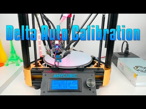 Needs to be activated in Marlin Needs to be activated in Marlin | ||
| Extrusion Multiplier | Usually 1.0 | ||
| Prime Nozzle | Prime the nozzle before starting the test pattern | ||
| Prime Extrusion Multiplier | The default of 2.5 results in roughly 1mm of filament for 10mm line length | ||
| Prime Printing Speed | Speed of the prime move | ||
| Dwell Time | Inserts a pause of x seconds before starting the test pattern to bleed off any residual nozzle pressure | ||
| Filename | |||
Notes on the settings:
- Fast Printing Speed and Slow Printing Speed should be significantly different or the K-factor effect will barely be visible.
- Use Bed Leveling requires a probe.
- For round beds the option Origin Bed Center is automatically activated.
- The overall width (X-direction) of the print depends on the Fast Speed Length and Slow Speed Length settings plus 5mm for the priming line.
 The length (Y-direction) depends on the K-factor Settings and Line Spacing.
 - The script checks to make sure the print fits on the bed. Verify it using a host software like Printrun or Repetier Host.
- Start and End Value for the K-factor determines the range that the test pattern will cover. For example a Start Value of 50 and an End Value of 150 will test a range of 100.
- The K-factor Stepping determines how many test lines are printed for the above range. For example, a Stepping of 10 and a range of 100 results in 10 test lines. A stepping of 3 would not work in this example as 100 cannot be exactly divided by 3. The script will throw an error message if an exact division is not possible. In this case either the range or the stepping needs to be adjusted.
- The Alternate Pattern has a second line of Fast Printing Speed to test 0 to Fast Printing Speed and back to 0 conditions.
 Best used with an increased Test Line Spacing and reduced K-factor range.
 - The proper K-factor depends on the filament, nozzle size, nozzle geometry and printing temperature. If any of these values change, the calibration might need to be repeated.
The following screen-shots show some examples of the test patterns
- Blue Lines are Slow Printing Speeds
- Red Lines are Fast Printing Speed
- Light blue lines are movements
Standard Pattern
Standard Pattern with Frame
Alternate Pattern with increased Test Line Spacing
45° rotated Alternate Pattern
how to properly adjust the table leveling sensor, semi-automatic auto-calibration test
Print quality on 3D printers depends on many factors. To ensure it, careful preparation of all units of the apparatus is necessary. Calibrating the 3D printer table is one of the most important preparatory steps.
What is table calibration and why is it needed?
For high-quality formation of a part from a filament on the desktop of a 3D printer, it is important to ensure a uniform distribution of mass over the surface.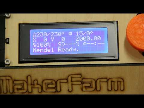 It is only possible with a perfectly horizontal level and an optimal gap between the table and the head nozzle. If the table has an uneven surface, then the gap will change in different work areas. The uniformity of the filament supply will be disturbed, which will lead to defects and deformation of the printed part. nine0003
Calibration consists of two main steps: leveling the surface over the entire working area and adjusting the vertical height of the head (Z-axis). Alignment can be done manually using the adjusting screws. More expensive printers have an automatic desktop calibration device. When adjusting vertically, the optimal gap between the nozzle and the table surface is set, which must maintain the specified value at any point in the working area. nine0003
Signs that the table is crooked and needs adjustment
The following signs indicate that the table needs to be calibrated:
- plastic does not stick to the surface, indicating an excessively thick layer;
- the bottom layer is peeled off the table during the subsequent application of the filament;
- gaps in the first layer or too thin lines;
- Plastic builds up around the nozzle when printing the first layer;
- layer thickness and extrusion line vary markedly at different points on the surface; nine0018
- in some places the nozzle touches the already applied plastic;
- The filament comes out of the nozzle in a spaghetti pattern, i.
 e. it twists.
There may be other signs that indicate an uneven application of a layer of plastic on the surface of the desktop.
Table Calibration Test
When manually leveling the table surface, the most commonly used point array test is Mesh Bed Leveling (MBL). The work surface is divided into a grid. In each of its nodes, the clearance along the Z axis is measured manually using a vernier caliper.
There are more accurate methods using test models. One of the simplest models involves printing circles in the center of the table and near all the adjustment screws. Printing is done in one layer with a thickness of 0.1–0.2 mm. When a difference in thickness is detected, it becomes clear which screw needs to be adjusted.
More complex test models require the printing of correct, but simple shapes. The hollow gauge cube 25 × 25 mm in size is popular. It allows you to evaluate the print quality of both the base and the walls. nine0003
Calibrating the 3D Printer to a Sheet of Paper
The most common way to calibrate the Z axis is to calibrate using a plain sheet of paper. The surface is meshed. A paper sheet is placed in each of its nodes between the nozzle and the table. The position of the extruder head is set so that the sheet can only be advanced with force. This coordinate is translated into a special G-command through the control computer program or through the printer menu. With manual calibration, it is simply recorded for future settings. This procedure is carried out at all grid nodes. Typically, the surface of a consumer printer is divided into a 3 × 3 grid, i.e. with 9nodes. You can increase the number of calibration points, but it is not recommended to create more than 49 points.
How to properly calibrate the 3D printer bed?
Different models of 3D printers may have individual features of adjustment and settings, but the general technique is typical for all devices. From the first time, it may seem to a beginner that the procedure is very complicated, but gradually it is brought to automaticity and does not cause problems.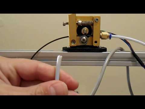 To eliminate errors, it is recommended that calibration be carried out at the same temperature to which it is heated during printing. For example, with ABS, you will have to warm up the table to 90-100°C. If during operation the surface is sealed with adhesive tape or cardboard, then they should be applied before starting the adjustment.
Table leveling tools
To calibrate the table yourself, you need to prepare the following set of tools and consumables:
- Calibration probe - thin plates with a precisely known thickness. You can use a strip from office paper 125-165 g/m 2 approx 10 x 4 cm.
- Wrench and screwdriver for adjusting screws depending on their design.
- Metal (preferably brass) brush and cotton cloth to clean the nozzle from adhering mass.
- Heat resistant gloves capable of protecting hands when heated to 110-120°C.
- Spatula, razor blades for scraping plastic off the tabletop.
- Laundry soap and cotton cloth for final cleaning from dirt and dust.
- Isoprene alcohol for thorough surface cleaning. nine0018
These tools and materials will help you to carry out a complete cleaning of the working area and manual leveling of the printer table, to set the required gap between the nozzle and the table.
Table preparation
The first stage of calibration is the preparation of the table. First of all, it is necessary to thoroughly clean its surface. With the help of a spatula and razor blades, all remnants of adhering plastic from the previous print are carefully removed. If the table has a special coating (for example, PEI), then the blade cannot be used, as it may damage the protection. nine0003
After removing the plastic, the surface is thoroughly washed with dish soap. Warm water is used. If the surface material permits, cleaning can be done with isopropyl alcohol applied with a cloth or paper towel. After wet cleaning, the surface is wiped dry with a cotton cloth. When preparing the table, do not touch its surface with bare hands, so as not to leave grease stains.
An important parameter is the table temperature during calibration. It is important to take into account that the metal table significantly changes dimensions with temperature fluctuations, and therefore it is recommended to calibrate at the same temperature that is maintained in the operating mode. The need to preheat the table is indicated in the instructions for the device. nine0003
Auto Calibrate Table
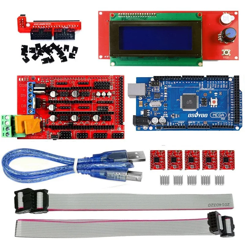
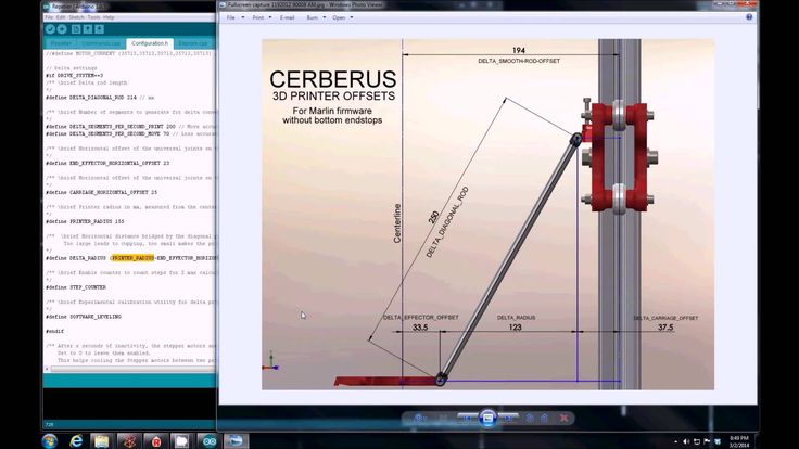
Many 3D printers rely on Marlin firmware for auto calibration. The adjustment procedure begins by opening the firmware code in the Arduino Software (Arduino IDE). There are different versions of the program, but the actions for them are the same. The main settings are made in the Configuration.h tab:
- In the Z Probe Options section, support for manual mode is enabled.
- In Bed Leveling, the type of calibration by a matrix of points is selected (#define MESH_BED_LEVELING). nine0018
- In the Mesh section, calibration parameters are set: offset from the zone boundary, number of points along the X and Y axes, adjustment step and movement range along the Z axis.
 It is recommended to use head movement commands.
After setting up the program, the calibration procedure itself is carried out in the following order:
- “Calibrate table” is selected in the printer menu.
- The "Autopark" mode is activated.
- Sets the drop height and Z of the table.
- The "Start" button is pressed, after which the movement of the table begins. nine0018
- A gap of about 0.5 mm is set. You can use a probe or a sheet of paper when calibrating.
Similar actions are carried out at all points along the X axis specified in the instructions for the firmware. All configured parameters are automatically saved in the printer, and therefore calibration is not required before each print run.
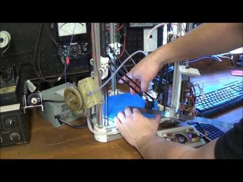
Manual calibration
Budget devices do not have automatic devices and table calibration is provided manually. It is carried out in this order:
- All adjusting screws are checked for smooth operation.

- The nozzle is cleaned of adhering mass.
- Each adjusting screw is loosened a few turns to increase the gap between the nozzle and the table.
- Calibration starts from one of the corners of the table. The nozzle of the extruder head is manually brought here. Use a feeler gauge or paper strip to set the optimum gap. Turn the adjusting screws carefully so as not to create excessive pressure on the probe. It can cause a response that can introduce an error. nine0018
- Similar actions are carried out in all corners. The level setting is checked at the center point. The clearance at all points must be the same.
When moving from one point to another, settings may fail. Therefore, it is necessary to check the previously established clearances. If they have changed, then everything is carried out in the second round. Sometimes it is necessary to carry out several circles of calibration. Next, the printer starts up and tests the correctness of the calibration.
Calibration sensor
During automatic calibration, the printer has touch control of the table movement, and a contact sensor is installed at the level of the nozzle. It is automatically able to determine the exact distance to the working surface. Signals are sent to the motion control body, which provides a precisely set gap. In some printer designs, the extruder itself has a feedback encoder, which allows it to act as a sensor.
Manual calibration is checked for correctness by examining the first test print layer. The following options are possible:
- Gap between nozzle and table is too small. This is evidenced by such factors: a very thin layer, and in some places its complete absence; accumulation of mass on the nozzle; the mass is not squeezed out onto the table at all.
- Gap too large. Signs: poor adhesion to the bed, peeling on subsequent printing, twisting of the filament when exiting the nozzle.
In the first case, it is necessary to move the head up along the Z axis, and in the second, on the contrary, lower it down.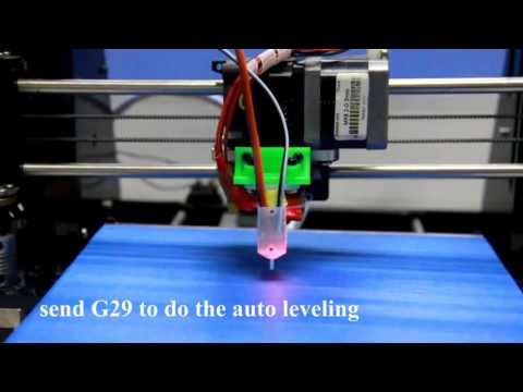 Test models provide a more accurate check. nine0003
Calibrating the table
Automatic and semi-automatic calibration can be achieved in several ways. The following options are most common:
- Through an external program. In this case, the special command G29 is used. So G29 S0 reads the current parameters of the points in memory; G29 S1 allows you to set the working body at the starting point; G29 S2 is for recording current information and moving the head to the next point. The M500 command allows you to enter all the necessary data into the machine's memory. nine0018
- Through the printer menu. The required items are selected in the Presets menu. The information needed for calibration appears on the display screen, the printer parks in a certain position. By clicking on the encoder, you can return the head to the starting point. When moving the encoder handle, the required clearance along the Z axis is set.
Important! The operator can choose the way he wants to control the auto-levelling.
How to prevent table curvature?
Any user wants to calibrate the printer bed once and so that its evenness is maintained during multiple print runs. What leads to the need for frequent calibration? First of all, this is excessive vibration of the device during operation, which knocks down the adjustment of the adjusting screws. To eliminate this cause, proper installation of the printer and the use of anti-vibration pads is necessary.
The second common cause is frequent and significant changes in print temperatures. The metal table is very sensitive to temperature changes, which knocks down the settings. It is important to carry out calibration with preheating of the table. nine0003
Important! Violations of the operating rules of the device can affect the imbalance. To prevent curvature, you must strictly follow the instructions for the device.
There are many ways to avoid problems. The most effective is the installation of special sensors (for example, the Boultach sensor) that control changes in table parameters. Protecting the surface by installing glass proved to be quite good. You can provide reliable protection with aluminum tape. nine0003
The quality of printing on a 3D printer largely depends on the correct settings of the device. An important step is the calibration of the desktop, which can be provided manually or automatically. If it is carried out correctly, all parameters remain in the printer's memory and a new adjustment is not required before each start.
- March 09, 2021
- 7846
Get expert advice
Calibration of the 3d printer table without any sensors
As you know, for high-quality printing on a 3D printer, it is necessary to carefully level the table surface. Unfortunately, this is not always possible. Quite often, the table is a curved surface, and even the use of glass does not completely solve this problem. Luckily in the latest Marlin firmware, more and more attention is paid to the ability to calibrate the surface of the table.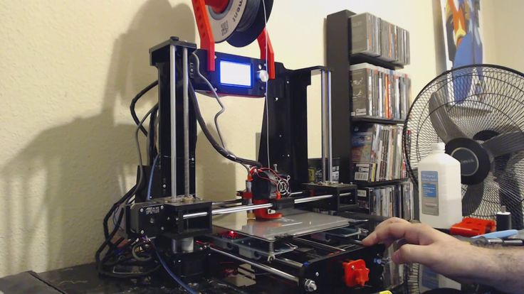 Fully automatic calibration requires the use of additional sensors, which is not always available, but in addition to it, it is possible to calibrate the table in manual mode. This is exactly what I want to talk about. nine0205 #define LCD_PROBE_Z_RANGE 4 // Range of movement of the Z axis relative to
// minimum value
#endif
Script to be executed after calibration. Here, by default, some gestures are made by the extruder, not the fact that they are needed. Not sure about this.
1 | // #DEFINE Z_PROBE_NEND_SCRIPT "G1 Z10 F12000 \ NG1 x15 Y330 \ NG1 Z10" After this one, |
The so-called Mesh Bed Leveling (MBL) is used for manual calibration. Those. point array calibration method. Accordingly, the surface of the table is divided into a grid, and the Z coordinates are measured at the nodes of the grid by moving the Z axis manually. Actually, only a sheet of paper and straight arms are needed for measurement.
At each point, we put a sheet of paper under the extruder nozzle and by moving the Z axis (either by sending a special G command through the software from the computer or through the printer menu) we achieve such a state when the sheet under the extruder can still be freely moved, and reducing the position of the extruder by one step already prevents the sheet from moving. After that, the current point is recorded and we continue with the next one and so on until the end. nine0003
At the end of the process, when all points have been measured, we write the results to the non-volatile memory of the printer and this is actually enough. In the future, there is no need to adjust the surface before each use - the saved values will be used.
By default, a 3×3 grid is used for calibration, i.e. 9 points, but if desired, a different number can be specified in the firmware (no more than 7 per axis, i.e. no more than 49 in total).
To further increase the accuracy of the calibration, you can warm up the table and extruder to operating temperatures before performing it. This will take into account and compensate for thermal expansion. nine0003
1 | M190 S65 ; Set the table temperature |
Through an external program
There is a special command for calibrating the table G29
-
G29 S0we read the current values of points in the printer’s memory. nine0018 -
G29 S1move the printer to the first point to start the setup process. In fact, the printer first parks to its original position, then moves to the first point. -
G29 S2write the current point and move to the next - Repeat process for all points
- Use command
M500to write measured values to printer memory
Through the printer menu
Select the following items in the Presets menu
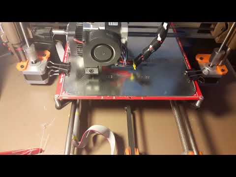
Then we see the following inscription on the screen and observe how the printer parks in the home position
Then the printer prompts us to click on the encoder.
After clicking, the extruder goes to the first point
And we see the Z-axis adjustment.
Click on the encoder to save the value and move to the next point. We repeat the calibration of each point (there are 9 in totalthings). After the last point, the printer will park and show us the following:
At this point, the calibration process can be considered complete and you need to save the settings to the printer's memory.
In my case, even such a manual calibration allowed to significantly improve the print quality. And noticeable to the naked eye. An additional bonus was that I stopped smearing the glass with glue for better adhesion - due to the fact that after calibration the printer takes into account the unevenness of the table, the first layer now fits absolutely evenly and sticks just fine. Again, this is immediately visible. Previously, due to irregularities, one part stuck worse and, as a result, the model fell off without a coating of glue.