3D printer temperature calibration
Optimal 3D printing temperature using temperature tower
I am currently working on a script that will inject the temperature changes in your gcode. Check back after a while.
One part of 3D printer's calibration is finding the optimal printing temperature. This temperature can differ based on the hotend design, filament manufacturer, material type or even ambient temperature.
The easiest way to quickly test a range of temperatures is by printing a temperature tower. Unfortunately, setting the temperature changes isn't obvious or even impossible with some slicers.
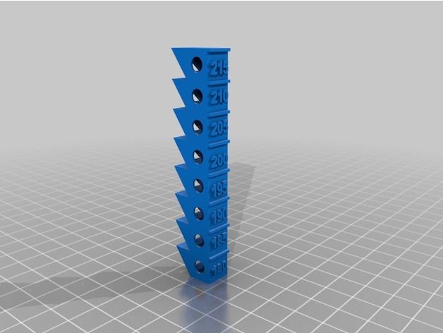
We'll be using this temperature tower by Jan Petersen from Thingiverse. I recommend it because the sections are evenly spaced and it includes a stringing test. Besides retraction settings, stringing is dependent on printing temperature so you might as well test it at the same time.
For PLA, I recommend testing temperatures in the range from 190°C to 215°C. Try 210°C to 240°C for PETG and 220°C to 250°C for ABS.
When your tower is finished, examine the overhangs, bridging and stringing. The ideal temperature is the lowest where the layers are still bonded together strongly (try breaking it apart) and where you can notice the least amount of artefacts. Also, the lower the printing temperature the better bridging you can achieve.
In some cases, the entire tower might look nearly identical. This is usually a sign of a good quality filament. I recommend selecting the temperature in the middle of the range to begin with.
Let's see how you can set the temperature changes using different slicers.
Simplify3D
Simplify3D has a built-in tool for setting different properties at different heights. This is great for changing infill percentage, but it can also make changing the temperature very easy.
You will find it under the Tools menu and then Variable Setting Wizard.
For our case, you should split the model beginning at 12mm and then at every further 10mm (i. e. 22, 32, 42 and so on).
Once done, Simplify3D will create a new process for every height that you've entered. The first process is attached to the bottom section of the tower.
Double click on each process, go to the Temperature tab and then select the Extruder temperature. You should set a single temperature at Layer 1.
Setting extruder temperature for the first process in Simplify3D.Repeat this for each process while changing the individual temperatures. When you're ready to slice it, be sure to select all of the processes before continuing.
Save the gcode and your tower is ready to be printed.
Cura
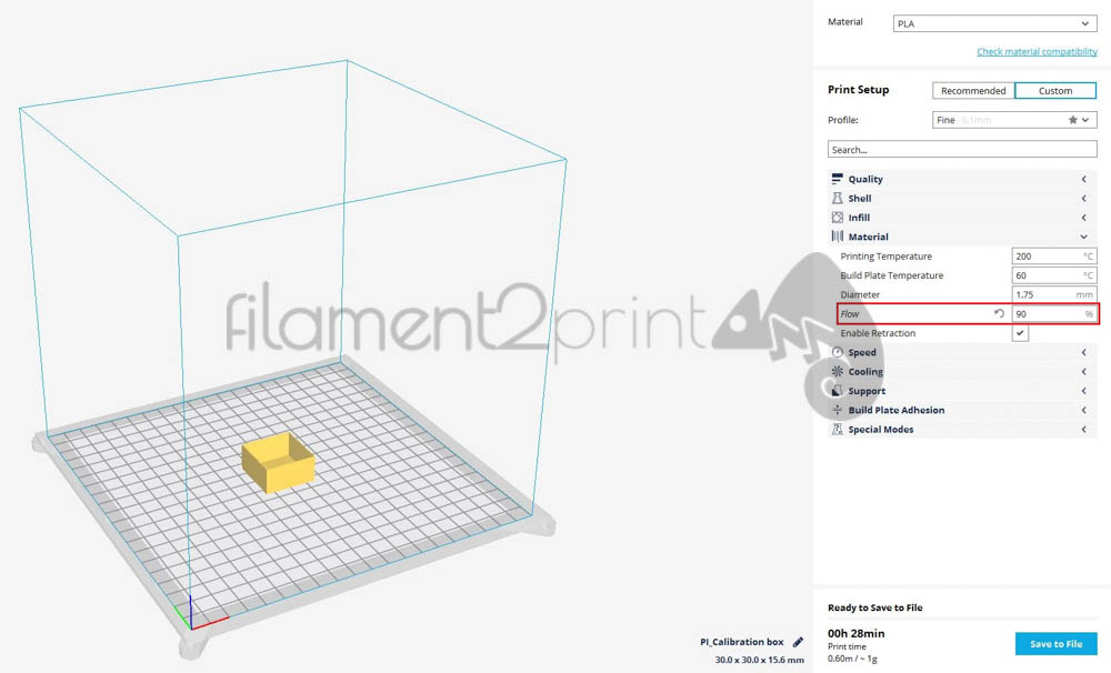
Cura doesn't have a built-in support for changing the temperatures, but there is a plug-in available that will help you do that. Best of all, it's already included with Cura.
Go to the Extensions menu and then select Post processing -> Modify G-Code:
Post Processing Plugin in Cura.
Begin by adding a new script. The one we are looking for is called ChangeAtZ. Then simply enter the height of the change and select the Change Extruder 1 Temp. Enter your desired temperature in °C. Add a new script for every temperature change and repeat the above.
All the changes for the temperature tower.Slic3r
Unfortunately, Slic3r does not currently support changing temperatures in any way. You will have to manually change the gcode as explained in the next section.
Set changes manually
If your slicer doesn't support the temperature changes or if you prefer to do it yourself, then you can edit the gcode file and set the changes manually.
Gcode files are written in plain text, so you can open them in any text editor.
To set the temperature changes, you have to search for a certain height and insert the appropriate command there. Specifically, you should search for the G1 Z12.0 command, as we want the first temperature change to occur at the height of 12mm. Unfortunately, this is where things get complicated.
Different slicers have slightly different ways of creating the gcode file. For example, Simplify3D and Slic3r will insert only the individual command to change the height, which is easy to find. Cura, on the other hand, will combine the height change with XY movement as well and the gcode would look like this (they're also using G0 instead of G1, but the end result is similar):
G0 X113.263 Y93.263 Z12.15
To further complicate things, if you have Lift-Z / Z-hop enabled, you might see a lot of commands that use the same height, but you need to find the one that actually changes the current layer.
Luckily, slicers also include human readable comments in the gcode, which helps greatly. All comments begin with the ; symbol at the beginning of the line.
In Simplify3D, the comment for layer height change looks like this and you should be able to find the actual G1 command right after it:
; layer 80, Z = 12. 051
051; feature inner perimeterG1 Z12.051 F720
With Slic3r, it should look like this:
;AFTER_LAYER_CHANGE;12.05; PURGING FINISHEDG1 Z12.050
Cura only comments on the layer's number, but the G0 command should be right after that:
;LAYER:60;MESH:Temperature_Tower.stlG0 X113.263 Y93.263 Z12.15
You might notice the F command at the end of some G commands; that is simply the movement speed.
Once you've successfully found the correct position in the gcode, insert the temperature change command into a new line just after the height change. The command to change the temperature is:
M104 S215 T0
where S is the temperature in °C and T0 signifies the first extruder.
Insert the M104 command into a new line right after the G0/G1 command.
In a similar fashion, find all the other locations where you wish to change the temperature (G1 Z22.0, G1 Z32.0, etc.) and insert the M104 command afterwards.
With that done, save the gcode file and you're ready to print the modified temperature tower.
How to Calibrate Your Hot End and Heat Bed with PID Tuning – 3D Printerly
Knowing how to calibrate your hot end and heat bed with PID Tuning is essential for making high-quality and consistent prints. This is something that every 3D printer user should know about, so I’ve decided to put together a detailed guide for this topic.
To calibrate your hot end and heat bed with PID tuning, you need to run specific commands in the terminal window of your printer’s firmware using a software such as Pronterface. This will give you new PID values which you will enter and save for calibrating the hot end and heat bed easily.
This is just a basic answer to get you started with PID Tuning. I will discuss the process in easy-to-understand details further ahead in the article, so definitely keep on reading for an in-depth guide.
It’s important for you to run the PID Autotune process before starting your 3D printing journey, but before we get into that, let’s understand what is this process and why it’s so crucial for your prints.
What is PID Tuning?
Proportional-Integral-Derivate or PID Tuning is a process that minimizes temperature fluctuations in the hot end and the heat bed of your 3D printer, both of which help with achieving the best quality. It’s usually done by using any software that can send G-Code commands to your 3D printer.
A few popular choices include Pronterface and OctoPrint.
PID Tuning is often compared to the Bang-Bang heating method which is more commonly used in ovens and home heaters.
However, the Bang-Bang method can be inaccurate for 3D printers and uses an inconsistent heating technique that doesn’t usually maintain a constant temperature. It basically sets an instruction to the heater to turn on and turn off between a range of temperatures.
PID Tuning is far more accurate and is capable of holding temperature steadily. It also plays a key role in determining how precisely the 3D printer handles temperature adjustments. People tend to get better printing results with this method.
It’s a great idea to run the PID Tuning method whenever you purchase a new 3D printer, change the hot end, or make changes to it. Doing so would allow you to easily fix any temperature variations causing your prints to fail.
With the initial explanation out of the way, let’s now get into the actual calibration part.
How Do You Calibrate Your Hotend Temperature?
To calibrate your hot end temperature, you will need to run an M303 command in the G-code terminal of a software like Pronterface so it goes into your printer’s firmware. After you get the calibrated values, you will enter and save them in your firmware so you don’t have to run PID Tuning again.
PID Tuning is a fairly straightforward process that can be easily done with the help of your printer’s firmware, which is Marlin in most cases. Make sure that your firmware version is up-to-date before you proceed with PID tuning.
Most slicer software have a dedicated terminal window that can be used to enter commands for your 3D printer. From Simplify3D to Pronterface and Repetier-Host, you can use whatever gets the job done.
I am going to break the PID Tuning process down into steps, so you can better understand the calibration method.
Step 1: To begin the manual PID Tuning calibration for your hot end temperature, we first need to make sure that our cooling fans are turned on to 100% to achieve the best results. An easy way to do that is by entering the following command:
M106 S255
I’ll be using Pronterface as my choice of software.
Step 2: After that, we will simply insert the PID Autotune command in the Pronterface terminal window, which is:
M303 E0 S200 C10
As soon as you run the command, the terminal will say “PID Autotune start” and your hot end’s temperature will start to rise for optimum calibration.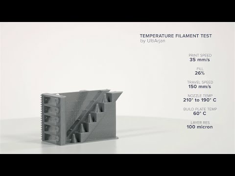
- M303 is the main command that triggers the PID Autotune calibration.
- E0 refers to the extruder and the extruder number. If you only have a single extruder in your 3D printer, E0 is the correct value for you.
- S200 specifies the tuning temperature at which the PID Tuning will occur. You can choose the temperature that you think is the average of what you normally go with.
- C10 is the number of cycles or iterations that the PID Tuning process will run. For the Marlin firmware, 8 is the recommended value, but anywhere from 6-10 works well.
Step 3: The calibration will take a couple of minutes to finish. When it does, you will see the values of 3 different constants pop up in the terminal: kP, kI, and kD. We will use these calibrated values and replace them with our existing ones using the following command:
M301 P(insert value) I(insert value) D(insert value)
The terminal will show you two lines of text and enter the values automatically.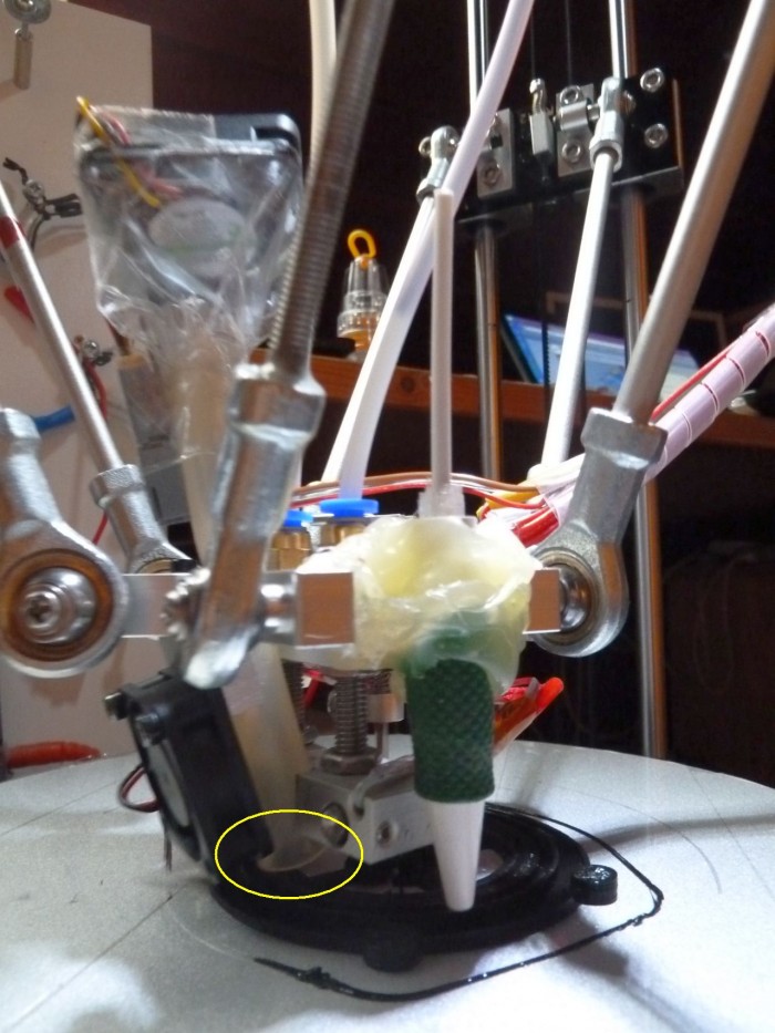
- I found out that you can automatically insert the calibrated values if you write U1 in the M303 command. You would then only have to save your values to the firmware, avoiding the previous step altogether.
Step 4: After that, we will simply save our values by simply using the command:
M500
This step is very important because if you don’t save the calibrated values, you will have to run the PID Tuning process each time after turning your 3D printer on.
That’s about it for calibrating the hot end with PID Tuning! You’ve successfully completed the whole process. If you ever wish to view your saved PID values, you can use the following command:
M503
People often ask how do you do PID Tuning for a hot end, and the answer is fairly simple, as you’ve understood by now. You can also watch the video below to get an illustrative idea of this calibration technique.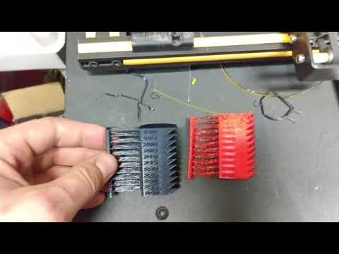
It’s also worth knowing that some 3D printers, including the original Prusa machines have a fully automated PID calibration process within the LCD interface.
You just have to set the temperature you want, and the autotune process will calibrate your 3D printer’s temperature automatically and save it too.
It’s usually done by going to the “Calibration” section, selecting “PID calibration,” and then setting the correct temperature to begin the process.
While that may or may not be available on your machine, the process of manual PID Tuning is equally effective and easy as shown above.
How Do You Calibrate a Heat Bed with PID Tuning?
To calibrate a heat bed with PID Tuning, you will need to run an M303 command in the G-code terminal of a software like Pronterface or OctoPrint so it goes into your printer’s firmware.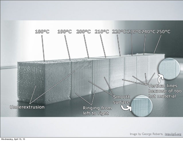 After you get the calibrated values, you will enter and save them in your firmware so you don’t have to run PID Tuning again.
Calibrating your heat bed with PID Tuning should be even easier, now that you know how to calibrate the hot end. The following steps are going to take it from here.
Step 1: In the G-code Terminal of your software, you will run the PID Tuning by entering the full command, which is:
M303 E-1 S60 C10 U1
As soon as you run the command, the terminal will say “PID Autotune start” similar to the hot end calibration and the process will start. It will take a couple of minutes for the tuning to conclude.
- M303 is the main command that triggers the PID Autotune calibration.
- E-1 is the number of the heat bed that will be calibrated.
- S60 is the temperature of the heat bed that needs to be tuned at which is 60° in this case.
- C10 is the number of cycles. It’s a good idea to let the test run 5-15 times for the best results.
- U1 automatically replaces your existing heat bed PID values with the calibrated ones so you don’t have to do another step.
Step 2: After you’ve added the values and the PID Tuning process has finished, you will have to save the calibrated values. To do that, you will run the following command:
M500
That’s about it for calibrating a heat bed with PID Tuning! You’ve successfully saved your values now and can start making picture-perfect prints with a consistent temperature.
You can also run the PID Tuning process in OctoPrint. This open-source platform also has a dedicated Terminal window where you can enter G-Code commands for PID Tuning.
After having your calibrated values, you can enter them in the G-Code Command window of the Cura slicer software for PID Tuning.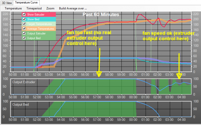
The command window in Cura can be found in the “Machine Settings” section which can be accessed by clicking on “Manage Printers.” You would then simply paste the values you’ve got after PID Tuning using the firmware.
The following video explains how to calibrate your heat bed and hot end temperature through PID tuning in Cura.
In Repetier-Host, PID Tuning is carried out in a similar manner. You simply have to click on “Print Panel” so the G-Code terminal can appear. Once done, all you have to do is enter a specific command to begin PID tuning.
Make sure your 3D printer and the software are connected to each other.
The 3D Print General made a more up-to-date video PID tuning your build plate, so check that out below.
How Do You Fix PID Autotune Errors?
Many people have reported experiencing some errors when calibrating their hot end and heat bed with the PID Tuning process. There are two errors that appear to be the most common of all. Let’s take a look at what they are and how to fix them.
- PID autotune failed! Bad extruder number
- PID autotune failed! Temperature too high
PID Autotune Failed! Bad Extruder Number
The “PID Autotune Failed! Bad extruder number” error typically occurs when you’re trying to calibrate your heat bed but the terminal window stops the process, showing you this text.
The error usually takes place when you’ve entered the command incorrectly in your G-Code terminal window. “Bad extruder number” refers to the “E-1” part of the PID Tuning command, and there’s a good chance that there’s a mistake in it.
There are two ways to fix the “Bad extruder number” error:
- Input the Command Correctly
- Enable PIDTEMP in the Marlin Firmware
Input the Command Correctly
To clarify again, the command for heat bed PID Tuning is:
M303 E-1 S60 C10
Notice that there is no spacing between E, the dash, and 1.
Enable PIDTEMP in the Marline Firmware
Another quick fix is to enable the PIDTEMP in the Marlin firmware. To do that, you simply have to launch the firmware, go to the Configuration.h area, and press “CTRL +F.”
This would allow you to search for “#define PIDTEMPBED”, where you would simply uncomment it so there is no “//” in front of it. Doing this has worked for many people who have been in the same boat.
One person even said that preheating the bed to 10°C did the trick for them. You can also try this step to see if it resolves your issue.
PID Autotune Failed! Temperature Too High
The “PID Autotune Failed! Temperature too high” error can occur when you’re trying to calibrate your hot end with the PID Tuning calibration process.
This error means that whenever the PID Tuning process tries to run, the temperature of the hot end overshoots and goes beyond the set temperature value.
For instance, if you’ve set the target temperature to 200°C for the hot end to calibrate at, the actual temperature will go drastically beyond the set temperature, about 30-40°C above thereby causing the “Temperature too high” error.
The good news is that several people who experienced this issue all reported one common fix.
Most 3D printers have a power supply of either 24V or 12V. All users reporting the “Temperature too high” error were using a 12V cartridge in a 24V powered system.
Therefore, a heater cartridge with the incorrect voltage supply causes the temperature to overshoot and result in this error.
In this case, you can easily replace your heater cartridge with the correct voltage for your 3D printer setup to quickly fix the “Temperature too high” error.
It's time to properly calibrate the nozzle temperature.
3D printing
Subscribe author
Subscribe
Don't want
48
Long suffered with the selection of printing temperature. It's time to overcome your laziness and figure out how to do it all right. To begin with, I began to look for a calibration column. There are a lot of them on the Internet, but they are all huge and kill a lot of time for proof printing. This is not my method. We take Solidworks and now the model is ready
Bollard 10mm thick and with 5mm sections for temperature change. Now the question is how to make the slicer change the temperature automatically? There is a question and there is an answer. Breaking a bunch of information found a solution (for those who use Cura 2.5)
The program itself has a TweakAtZ plugin, it will help us with changing the temperature according to our conditions
since the bar is made from 235 to 180, then we will check and will be in this temperature range .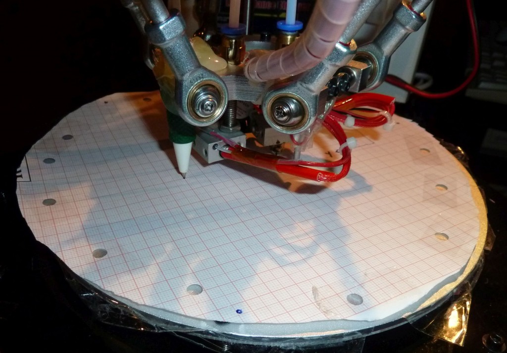
Select menu item
Here the first line is responsible for the first layers and in order not to change the settings of the whole chicken for calibration, I just made the first layer at 235 degrees with twice the thickness of the first layer - 0.4. From a layer thickness of 0.4 mm, the temperature will rise to the first limit of 235 degrees
The second line will be from a thickness of 5 mm (equal to division) and will be equal to 230
The third line will be 10 mm and 225 and so on (+ 5 mm to the previous one and - 5 degrees and so on up to 180.
We compile the code and get the Gcode configured for our printer with temperature selection.Such files can be prepared for other parameters too.0003
I hope the article will help someone. Well, as a memo it will be for me too :) thank you everyone everyone is free :)
link to my column for those who are too lazy to do it http://www.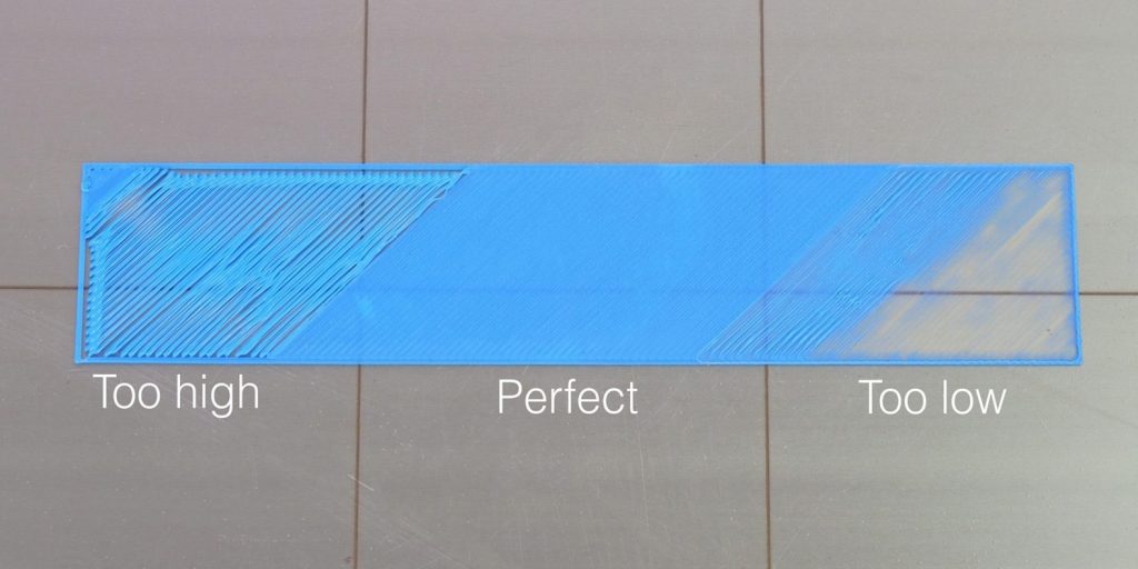 thingiverse.com/thing:2276432
Subscribe to the author
Subscribe
Don't want
48
Article comments
More interesting articles
eleven nine0003
Follow author
Follow
Don't want
Introduction
So, good day to all! This is my second post...
Read more
3Dtool
Loading
01/05/2023
724
-6
Subscribe to the author
Subscribe
Don't want
Hello everyone, Friends! With you 3DTool! nine0003
This year, at your request, we decided to.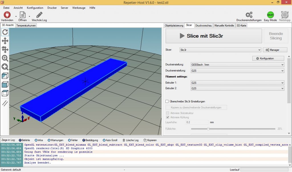 ..
..
Read more
304
Subscribe to the author
Subscribe
Don't want
Hello dear community!
If the experiment was successful, then something is wrong here...
Read more
Read the blogs
PID calibration or what to do after replacing the heater or thermistor
In this article, we will talk about how to calibrate the PID of a 3D printer after replacing the heater, thermistor, and in some cases the heating block.
As you know, nothing is absolutely identical in nature, including two absolutely identical thermistors, heating blocks and heaters. Well, it is quite logical that after replacing them, the 3D printer starts printing somehow wrong. This is due to the wrong PID.
What is a PID? Wikipedia tells us this:
The Proportional-Integral-Derivative (PID) controller is a device in a feedback control loop.
Used in automatic control systems to generate a control signal in order to obtain the required accuracy and quality of the transient process. The PID controller generates a control signal that is the sum of three terms, the first of which is proportional to the difference between the input signal and the feedback signal (error signal), the second - to the integral of the error signal, the third - to the derivative of the error signal. nine0003
Source
In simple terms, these are 3 coefficients that the microcontroller uses to control the heating, in our case, the extruder. These coefficients are unique for each bundle of heater and thermistor, respectively, when one of them is replaced, the coefficients also change.
Thus, after replacing the heater or thermistor, it is necessary to calibrate the PID for the correct operation of the 3D printer.
It is worth considering that most 3D printer manufacturers do not calibrate the PID of each printer, but use some average values that will work on a particular printer, as God wills. nine0003
So, it is necessary to calibrate the PID of the extruder in the following cases:
- On a new 3D printer
- When replacing thermistor
- When replacing heater
- When replacing the heating block (not always)
Let's figure out how to do this using the Marlin firmware as an example.
Marlin firmware already has a built-in automatic PID calibration mechanism, as well as the ability to change coefficient values without 3D printer firmware. nine0003
The only condition under which this will work is that the non-volatile EEPROM is unlocked.
Let's analyze the PID calibration process without flashing using the example of the Anycubic Mega-S 3D printer
Attention! not on all models of 3D printers EEPROM is unlocked. Check this before performing this operation.
You do the following steps at your own risk. We are not responsible for no result, negative result. nine0102
For PID calibration we need.
- Pronterface Program You can also use Repiter Host, but Pronterface is more convenient.
- USB cable for connecting 3D printer to PC
- Drivers for 3D printer. They need to be installed.
If you have a CURA slicer running, close the program, and even better, restart your computer.
We connect the 3D printer to the PC with a cable.
Launch the Pronterface software and connect to the 3D printer. To do this, select the COM port on which the 3D printer was detected, select the connection speed and press the button CONNECT
In our case it is COM5 speed 250 000
- something krakozyabry, it means you have chosen the wrong connection speed. Pick it up experimentally.
If nothing appears in the window on the right except for the text Connecting…, then the computer cannot communicate with the printer for some reason (the port is incorrectly selected, there is no driver, problems with the cable, etc.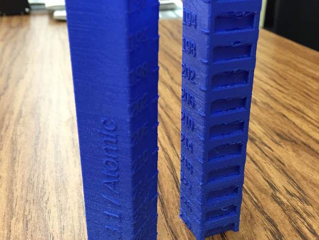 )
)
After we have successfully connected to the 3D printer, we need to enter the command for auto PID calibration in the command line. It has the following view:
m303 E0 C10 S240
where M303 is a PID
E01111 - for which PID
C10 is the number of heating/cooling cycles, according the results of which the microcontroller of the 3D printer will calculate the optimal PID
S240 is the temperature at which the calibration will be performed. It is recommended that you choose the temperature at which you print most often.
We enter the command in the line for entering commands, press the SEND button and wait for the result of the execution. You will have to wait a few minutes.
During the execution of the command, the following values will be displayed in the window. This means that the printer is calibrating.
After the calibration process is completed, the printer may make a beep sound (if it can), and the window will look like this:
As a result of the PID calibration, we got the following coefficients:
They need to be written somewhere.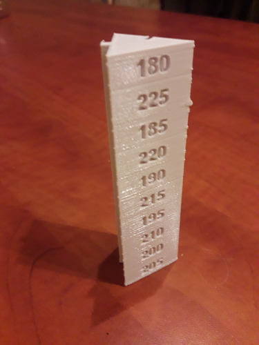 Now let's transfer them to the 3D printer's memory.
To do this, execute the following command:
M301 P14.62 I1.08 D49.42
equal to the define DEFAULT_Kp parameter obtained during calibration)
I1.08 - coefficient i (its value is equal to the parameter define DEFAULT_Ki obtained during calibration)
D49.42 - coefficient d (its value is equal to the parameter define DEFAULT_Kd obtained during calibration) values.
Insert the command into the pronterface command line and press the button SEND
The result of the command execution:
With the command M500 we save the new PID values in the 3D printer memory. nine0003
To check that everything worked out for us, turn off the 3D printer and disconnect the cable from the PC.
In a minute, turn on the 3D printer and connect its cable to the computer. Again, through the Pronterface program, connect to the 3D printer and execute the command M503
If, as a result of executing the command in the output window, we received the PID values obtained during calibration:
This means that the PID calibration process was completed successfully.