Mark forge 3d printer
Industrial Additive Manufacturing Platform | Markforged
The Digital Forge Platform
Our smart platform makes it easy to solve tough manufacturing problems.
Precision machines that consistently improve.
See all printers
Metals. Continuous fiber. Composites. All at your command.
See all materials
Software that dovetails into your workflow.
Learn more
Turnkey Simplicity
The Digital Forge is purpose-built to integrate quickly and seamlessly into your manufacturing ecosystem.
Robust Parts
Print repeatable, production-quality parts using materials curated for durability and strength.
Perpetual ROI
See returns in weeks, not years. Keep increasing your bottom line with consistently improving machines and streamlined operations.
Unlocked Potential
Transform your supply chain, unleash workforce creativity, and create a culture of innovation.
News & Insights
Resources
-
News & Events
Markforged to Expand into Mass Production of End-Use Metal Parts Through Digital Metal Acquisition
-
Learn Blog
AM Forward Program: Everything You Need To Know
Everything you need to know about the federal Additive Manufacturing Forward program launched in May 2022.
-
Learn Blog Customer Success Stories
Vestas
Vestas is a global leader in wind energy using Markforged’s Digital Forge additive manufacturing platform in support of its direct digital manufacturing (DDM) program to free up manufacturing processes from relying on outside suppliers and provide a knowledge base for collaboration.
-
News & Events
Markforged Expands Software Offering with Acquisition of Teton Simulation Software
-
Learn Blog
Introduction to Eiger™ Fleet
Eiger Fleet, a cloud-based software solution, is designed to accelerate the adoption of and streamline additive manufacturing operations at scale.
 It offers increased operational efficiency and visibility, enterprise-level access management, and simplified workflows.
 -
Learn Blog
What are the Benefits of Adopting Metal 3D Printing? Business Side and Technical Benefits
Metal 3D printing correctly can greatly improve business efficiency and agility — whether through eliminating the need for detail drawings and machine programming, or drastically shortening lead times that bog down product development processes. Learn about the full range of business and technical benefits.
We work with
Talk to an expert Request a demo Try the softwareLet’s get started.

Industrial 3D Printers: Strong Parts. Right Now
A complete line of machines made to create functional parts. Industrial 3D printers that consistently improve with a connected platform and precision construction.
Talk to an Expert
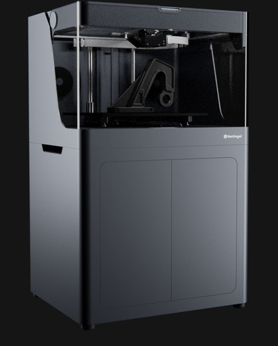
Flagship Industrial Composite 3D Printer
FX20™
An ULTEM™ filament capable production platform for big, strong, high temp parts — usable from factory floor to flight. The ULTEM™ and 9085 trademarks are used under license from SABIC, its affiliates or subsidiaries.
Discover theFX20™
Flagship Metal 3D Printer
Metal X™ System
An accessible way to go from design to metal part — the Metal X System is a leading end-to-end additive manufacturing solution.
Discover theMetal X™ System
Flagship Industrial Composite 3D Printer
X7™
The turnkey industrial 3D printer for many types of functional parts.
Discover theX7™
Flagship Industrial Composite 3D Printer
X7™
The turnkey industrial 3D printer for many types of functional parts.
Discover theX7™
Industrial Composite 3D Printer
X5™
The industrial 3D printer for Continuous Fiberglass reinforced parts.
Discover theX5™
Industrial Composite 3D Printer
X3™
The refined Industrial FFF 3D printer for micro carbon fiber filled nylon parts.
Discover theX3™
Desktop Series
Drive innovation right from your desktop. Powerful professional 3D printers designed to maximize the capabilities of high-quality composite printing.
Explore our Desktop Series
Flagship Desktop Composite 3D Printer
Mark Two™
The powerful professional Carbon Fiber 3D printer for aluminum-strength parts.
Discover theMark Two™
Desktop Composite 3D Printer
Onyx Pro™
The workhorse professional 3D printer for Continuous Fiberglass-reinforced parts.
Discover theOnyx Pro™
Desktop Composite 3D Printer
Onyx One™
The FFF desktop 3D printer for tough, high quality Onyx parts.
Discover theOnyx One™
Strong Parts
Every Markforged industrial 3D printer is built to create strong parts. Period.
Designed for Reliability
Precision design and construction yields predictable, repeatable results.
Platform Connected
Monitored and controlled by a central platform — fabricating functional parts is as easy as pressing print.
1. Design & Slice
Design a part in your chosen CAD platform and export it as an STL. Upload the STL to Eiger and select your material and orientation. The software slices your part, automatically generating a raft, supports where necessary, and a layer of release material between the raft/supports and the part itself.
About Our Software
2. Print
Metal powder bound in plastic is printed a layer at a time into the shape of your part. Parts are scaled up to compensate for shrinkage during the sintering process.
Available Materials
3. Wash
After printing, “green” parts are placed into the Wash-1, which uses a debinding fluid to dissolve most of the plastic binding material.
Learn More About the Metal X System
4. Sinter
Washed “brown” parts are placed in a Markforged furnace, where they are heated with a material-specific profile to remove the remaining binder and solidify metal powder.
Learn More About the Metal X System
5. Use
Parts come out of the sintering furnace as fully metallic objects and can be used in manufacturing, tooling, and prototyping operations.
See 3D Printed Parts At Work
1. Design & Slice
Using the CAD platform of your choice, design a part. Many different parts can be printed, but following Design for Additive Manufacturing (DFAM) guidelines enables you to fully leverage the unique strength and flexibility of Markforged composite printers. Upload the STL to Eiger and select your base materials and part orientation.
About Our Software
2. Reinforce
Unique to Markforged composite printers with Continuous Fiber Reinforcement (CFR), Eiger enables you to print with two types of printing media: a Composite Base filament and a Continuous Fiber. Configure the reinforcement to your application, choosing a Continuous Fiber and layers to reinforce.
Available Materials
3. Print
A Markforged composite printer automatically prints your part layer by layer. Composite Base material is printed through one nozzle, and Continuous Fiber is laid in-layer by a second nozzle and extrusion system.
Discover the X7
4. Use
The resulting composite part consists of a Composite Base and a Continuous Fiber, and can be used in a wide variety of industrial applications.
See 3D Printed Parts At Work
Talk to an expert Request a demo Try the softwareLet’s get started.
3D Printhead Kinematics
In the production of various functional products such as machine parts and structural elements, quality assurance issues are of particular importance. So, due to the layer-by-layer formation of a printed product, stripes form on its surface. The stepped look is best seen on curved and curved surfaces. It becomes more pronounced as the layer thickness increases. Stepping may not affect the strength of the printed product in any way, it most often only increases its roughness. However, if the product does not require a low level of roughness per se, but only the appearance (for example, if we are talking about instrument cases), you can resort to a simple finish of the outer surfaces. Significant dimensional errors and distortion of the shape of products that can be tolerated during printing are a much bigger problem. In the most common 3D printers using layer-by-layer fusing technology (FFF, Fused Filament Fabrication), two main factors are of decisive importance: temperature shrinkage of the material and positioning error.
The shrinkage of the printed object is determined by the physics of the process: the molten material is squeezed onto the platform layer by layer and solidifies in the form of the final product, and in the process of cooling from the melting temperature to room temperature, it seems to shrink.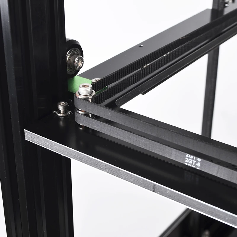 Different materials can shrink more or less, but this process is always uncontrollable. In some cases, it can be assumed that shrinkage occurs uniformly in all directions by a certain percentage. Based on this assumption, corrections can be made to the control program (G-code) that can partially compensate for the shrinkage error.
An equally important role in ensuring accuracy is played by the positioning accuracy of the working body of the equipment, i.e. the print head of the printer.
To date, many options have been proposed for building a system for moving the print heads of 3D printers, however, systems based on belt drives are most widely used. This is due to the fact that the load acting on the print head during operation is relatively small (unlike metal-cutting machines, printers do not have such a powerful disturbing factor as cutting forces), so such kinematic schemes provide sufficient rigidity. At the same time, they are characterized by simplicity, economy and high speed of movement, which positively affects productivity. However, at the moment, the factors affecting the accuracy of the positioning of the print head in such systems remain poorly understood. There are no practical recommendations on choosing the configuration of the kinematic scheme and the dependence of positioning errors on the operating parameters (mass of the print head, dimensions of the construction area, belt pretensioning, gaps in movable joints, etc.) of the 3D printer.
Among the known variations of kinematic systems based on belt drives, one of the most common is the H‑Bot single circuit. It has a single belt in the form of the letter “H” and is driven by two motors ( fig. 1 ). A small number of moving elements in this circuit reduces the inertia, which positively affects the positioning accuracy. It also increases due to the fact that when the motors are rotated by 1 step, the print head travels a linear distance equal to half a step. However, in this system, the unidirectional rotation of the motors required to move the printhead along the X-axis results in multidirectional forces that cause the transverse rail to skew relative to the longitudinal ones.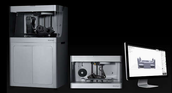 The non-perpendicularity of the guides leads to the appearance of a gross error in the shape of the final product - for example, an object with a rectangular section will take the form of a parallelogram. In addition, the fastenings of the transverse guide to the longitudinal ones suffer from a repeated cycle of rectification skew, and the system resource is reduced.
Fig. 1. H‑Bot kinematic movement system
In it, the use of two drive belts balances the impact on the moving elements, thereby maintaining their correct geometric arrangement. The system uses more bypass rollers than the H‑Bot system (2 more). However, in this scheme, it becomes necessary to ensure equal pre-tensioning of both circuits. In the event that one belt is tightened more than the other, with unidirectional rotation of the motors, as in the H-Bot scheme, a pair of forces appears applied to the transverse guide. The resulting moment of forces rotates the movable unit in the XY plane, this causes a violation of the perpendicularity of the guides and also leads to positioning errors and accumulative deformation of the elements of the movement system. To avoid cases of belt intersections, their contours are located in different planes - this leads to additional bending moments on the print head carriage.
Fig. 2. CoreXY motion system
Compared to H‑Bot, the dual circuit motion system has less dynamic error caused by stretching of the belts during acceleration and deceleration of the print head: the presence of two parallel belt branches doubles the rigidity of this oscillatory system.
0027 fig. 3 ). This moving device has two belt circuits. The primary circuit belt is fixed on both sides of the carriage with a single guide roller and performs the function of moving the head along the X axis. 3. Kinematic movement system Markforged
The same circuit is driven when moving along the Y axis, but in this case the second circuit belt is also driven, fixed on the movable unit. Despite its simplicity, the scheme combines the disadvantages of both previous schemes - it requires equal belt tension and, at the same time, regardless of the tension, it tends to rotate the movable unit during unidirectional rotation of the motors.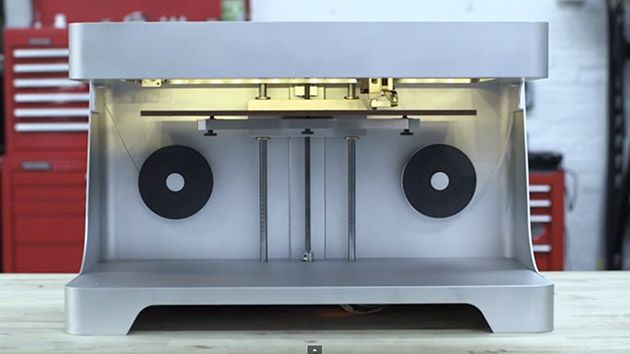 This scheme is not widely used among manufacturers of additive plants.
Another kinematic system in which each motor is responsible for moving along its own axis is the Ultimaker system. In it, the print head is driven by a transverse guide, which is fixed in the transverse blocks and slides along the central longitudinal guide, fixed in the longitudinal blocks. This kinematic scheme has high structural rigidity and low inertia of the print head. The system also includes closed loop belts, which in theory should provide equal belt tension. These characteristics have a positive effect on positioning accuracy. Nevertheless, the scheme is sensitive to the initial mutual setting of the guides, the error of their relative position is reflected in the shape of the printed products, similar to the skew of the movable unit in previous systems. The disadvantages of the Ultimaker circuit include a complex implementation and high quality requirements for linear motion components.
Fig. 4. Ultimaker Kinematic Handling System
There are other belt driven motion systems that have become less common due to significantly greater complexity or more disadvantages.
In the production of its own 3D and 5D printers (Stereotech 320 and Stereotech 520 ( fig. 5, 6 ) Stereotech uses its own patented STE HeadMotion print head movement system ( fig. 6, 7).
Fig. 5. Stereotech 3D printers: Stereotech 520, Stereotech 320
Fig. 6. General view of the Stereotech 320 3D printer in a housing without a top cover with a kinematic system STE HeadMotion
The print head movement system includes one transverse and two longitudinal rail guides. The longitudinal guides are rigidly fixed on the base in the direction of the Y axis, the transverse guide is located along the X axis and is connected to the longitudinal ones through the carriages. The print head moves with two drive belts, as in the CoreXY scheme, to increase the rigidity of the drive system and reduce the inertial error. The ends of the belts are fixed to form two connected contours on the print head carriage. The symmetrical arrangement of the contours compensates for bending moments on the bearings and guides of the moving parts of the system.
To solve the problem of ensuring equal belt tension in the circuits, a tension equalization unit is included in the device. It is a lever with two rollers at the ends (each of which is part of a separate circuit), hinged on the base with the ability to rotate in the XY plane, and works on the principle of a swing. When a difference in tension forces appears in the circuits, the lever turns, the rollers move, and both circuits return to equilibrium. To dampen vibrations, dampers are installed at the ends of the lever ( fig. 7, 8 ).
Fig. Fig. 7. STE HeadMotion kinematic movement system with tension force equalization unit
Fig. 8. Calculation diagram of the tension force equalization unit
The movable unit with a transverse guide is made in the form of a single portal to increase the rigidity of the device, which also has a positive effect on positioning accuracy.
The motors are mounted on the base of the printer to reduce the mass of moving parts and reduce inertial moment. Their unidirectional or multidirectional movement causes the print head to move along the X or Y axis, respectively; turning each motor individually moves the head diagonally.
The frame base of the moving device can be made of connected profiles, plates and other elements that are arranged in parallel and connected transversely to each other.
heads, and thirdly, an increase in the service life of a 3D printer. The device is universal for two printer models: Stereotech 320 and Stereotech 520, which uses innovative 5D Additive Manufacturing technology. ■
■
Author: I.S. Torubarov, A.A. Bityushkova, LLC Stereotec, [email protected]
Source Additive Technology journal No. 2-2020
Kinematic Systems for moving the 3D printer printing head, LLC Stereotec. magazine "Additive Technologies" No. 2-2020, STE HeadMotion kinematic system, Stereotech 320, Stereotech 520, 5D Additive Manufacturing technology
Wanhao Duplicator 9/500 mark II 3D printer
Go
10% discount on materials Free shipping within Russia
Official distributor
We work directly with manufacturers.
Any form of payment
The opportunity to see the 3D printer in action in our demo room.
Own warranty service
Warranty and post-warranty service for equipment purchased from us.
Permanent 10% discount on consumables
When you buy a 3D printer from us,
, you get a 10% discount on all consumables.
3D printer Duplicator 9/500 mark II is a new model from Wanhao with an all-metal extruder MK10, for printing a wide range of different plastics.
The D9 printer line has the largest printable surface area compared to other Wanhao models.
The volume of the construction area for D9 / 300 is 30x30x40 cm. For D9 models/ 400 and D9 / 500 area is 40x40x40 cm and 50x50x50 cm respectively. The name of the model depends on the size.
From the previous modification Wanhao D9 / 500 mark II differs in the following:
- The main advantageous difference from the previous Wanhao D9 /500 mark II model is that this printer model is reinforced with reliable rigid supports.
 Thanks to them, printing has become much more stable. This is especially important when printing large models.
- Y-rail with 4 rollers (instead of 3) for smooth movement.
- Improved wire retention.
- Upgraded fan for more accurate printing.
- Models D9/300 and D9/400 have a double-sided print surface. PVC sticker on one side and embossed glass on the other. (at D9/500 only PVC printing surface).
- Automatic "smart" calibration for BLTouch sensors.
- Models D9/400 and D9/500 have a more rigid design, due to the double profiles in the Y-axis.
- Updated extruder cable.
- For the most accurate layer thickness, dynamic Z offset is adjusted during printing.
- Models D9/400 and D9/500 have a new wide belt and large pulley.
- The printer was supplemented with navigation for installing an SD card.
- Function to resume printing after a power failure.
| 3D printer | 1 PC |
| Thread spool holder | 1 PC |
| Thread spool stand | 1 PC |
| Power cable | 1 PC |
| USB cable | 1 PC |
| SD card 8GB | 1 PC |
| Hex screwdriver | 1 PC |
| hex key | 1 PC |
| Hex head bolts | 6 pcs |
| Cable ties | 2 pcs |
| PLA Plastic Coil (Random Color) | 1 PC |
| Additional sticker for the printed table | 1 PC |
| User manual in Russian in electronic form | 1 PC |
| Nozzle cleaning needle | 1 PC |
Most recently, Wanhao released three truly large printers - the Wanhao Duplicator 9/300, D9/400 and D9/500. We decided to dot the "i" and prepared a review of the Duplicator 9/300.
Read more
Payment and delivery
Delivery scale
Delivery to all regions of Russia and countries of the Customs Union.
Free shipping
When you buy a 3D printer (except assembly kits) you get free shipping.
Cash
In our store you can pay for your order in cash.
Online payment on the website
You can pay for orders with a bank card on the website of our online store.
Buyers with this product
Add to compare
Product added to compare Go
Available
Plastic reel Tiger 3D PLA+ 1.75 mm., 1 kg., black (TGRPLA+175B1) Plastic for 3D printers
Add to compare
Product added to compare Go
Out of stock
Plastic spool Tiger 3D PLA+ 1.