Customize 3d printing
Shapeways: 3D Printing Service Online
3D Printing Service
Create and customize. Streamline and save. Break down design barriers and scale your business with Shapeways 3D printing services.
Why 3D Printing?
Reduce Assembly Time
Don’t waste time putting products together! Rely on 3D printing to make complex geometries that can be printed as one piece—or consolidated in one build.
Fast Turnaround
Working on a project for a customer that has to be just right? Get models back fast, and 3D print new iterations, if needed, for final feedback and production.
Reliable Quality
Proprietary processes, expert 3D printing operators, and inspections are our secrets to delivering exceptional, quality products every time.
Parts 3D Printed
3D Printing Technologies
Materials and Finishings
Countries Shipped
Customers Served
Cutting Edge Technologies
Manufacture high-quality products in over 90 of the best materials and finishes, from plastics to metals.
HP Multi-Jet Fusion
- Nylon 12 with a smooth and finished surface
- Exhibits incredible strength, durability and stiffness
- Supports complex geometries and thin features Learn More
ExOne Binder Jetting
- Steel infused with Bronze
- Supports large parts
- Strong metal with an industrial look and feel Learn More
Our Services
Production Parts
Upload customized models for 3D printing service—ensuring durability and strength in materials that result in end-use products meant to last. Learn More
Rapid Prototyping
Take the guesswork out of product development with 3D printing services for high-performance models used in meetings, testing, and perfection of final parts. Learn More
Finishing
Whether designers prefer polishing, smoothing, dyeing–or a combination of finishing techniques–Shapeways 3D printing services can perfect those final touches with shine, gloss, and color. Learn More
Professional Design Services
Bring your idea to life with 3D file design and optimization. Through our partnership with ZVerse, every customer has access to expert 3D Design solutions for any project need. Learn More
Rapid Prototyping
Our high quality printing enables you to assess factors such as ergonomics, usability, manufacturability, and material testing. Learn More
E-commerce Integrations
Launch your business through our marketplace by connecting to the Shapeways platform through our API, Shopify, or Etsy E-commerce Integrations. Learn More
Materials
Nylon 12 [Versatile Plastic]
Nylon 12 [Versatile Plastic] is a durable nylon plastic that can be used for a wide range of applications, both for prototyping and for end products. Printed using Selective Laser Sintering (SLS) 3D printing services, when thin, it's flexible enough for hinges and springs and when thick, strong enough for structural components. Learn More
Accura 60
Accura 60 is a translucent and rigid acrylate-based plastic. Shapeways 3D prints this material using a large-format Stereolithography (SLA) printer capable of producing small to large parts with high resolution and detail as well as smooth surfaces with limited layer lines. Learn More
Stainless Steel 316L
Stainless Steel 316L is manufactured using ExOne’s ‘Triple Advanced Compaction Technology’ with Binder Jetting. Unlike our Steel that is infused with bronze, this material is a single alloy, composed of pure Stainless Steel. Learn More
Nylon 12
Nylon 12 (Versatile Plastic) is a durable nylon plastic that can be used for a wide range of applications, both for prototyping and for end products. Printed using Selective Laser Sintering (SLS), when thin, it's flexible enough for hinges and springs and when thick, strong enough for structural components. Learn More
Accura 60
Accura 60 is a translucent and rigid acrylate-based plastic. It is 3D printed using a large format stereolithography (SLA) printer capable of producing small to large parts with high resolution and detail as well as smooth surfaces with limited layer lines. Learn More
Stainless Steel 316L
Stainless Steel 316L is manufactured using ExOne’s "Triple Advanced Compaction Technology" with a binder jetting system. Unlike our Steel that is steel infused with bronze, this material is a single alloy, 100% Stainless steel 316L. Learn More
Testimonials
I like the ease of use in the Shapeways platform, being able to 3D print on-demand orders for the first time, and most of all–being able to scale my business. In the beginning years ago I basically had the change in my pocket and a credit line at my bank so I couldn’t order a ton of things, and you never know what’s going to sell.”
Steven Jaworski
Owner | Voytek Medical
During the process, we used Shapeways capabilities to 3D print many prototypes. That meant we had the option to iterate very quickly, print objects, and test them to see if they were working correctly in terms of complexity, or too much complexity. ”
”
Yonatan Assouline
Manager & Co-Founder | Flamingo Works
Shapeways was really great when we worked together before, which led us to reach out again. It’s been so helpful to talk with them about what we could do in every aspect of 3D printing and finishing, and it saved us a lot of time in experimentation.”
Nathan Lachenmyer
Director of Technology | Sitara Systems
Previous Next
Recent Articles
Trusted by Businesses Around the World
Design, Upload, and 3D Print Your Files
Design, Upload, and 3D Print Your Files
3D print with Shapeways by creating complex products previously impossible with traditional manufacturing. Create sophisticated 3D printed ideas and designs, upload 3D print files, and expedite product development.
From sketch to the final 3D printed product, Shapeways allows you to choose advanced 3D printing materials, technology, and feedback for 3D print files. This ensures quality manufacturing for assembly and fit, functionality, and high-performance parts for applications like aerospace or medical.
Upload a File
Contact Sales
Have a 3D File Ready?
Create your 3D model and upload the 3D print file to Shapeways. Don’t have a 3D file? Shapeways can help.
Shapeways 3D prints and post-process your product.
Your 3D print is shipped expediently and arrives ready to use!
Upload a Model to 3D Print
Whether you are uploading 3D models for jewelry or automotive parts, Shapeways instantly analyzes the 3D file for printability. While most 3D models are uploaded successfully, if an issue arises, Shapeways file fixers can help regenerate the 3D file or provide customized feedback. Inspections, proprietary processes, and expert 3D printing operators lead to exceptional products.
Explore Materials
Proper selection of 3D printing materials is key as they must be compatible with 3D printing technology and optimized for project requirements. From plastics to metal, Shapeways offers over 90 materials and finishes–and additive manufacturing services for any project.
3D Print Design Tips
While excellence in product development depends on optimized modeling, prototyping, and quality management, 3D printing design guidelines play a critical role in the outcome of every 3D printed part. Check out the following resources for assistance in taking your 3D design from concept to market.
Services for Your Business
- Use Shapeways 3D printing services to create complex 3D printed products for you.
- Receive 3D printed parts quickly, print new iterations, or rapid prototypes as needed.
- Rely on expert 3D printing operators and inspections for delivery of quality products.
- Choose from a range of additive manufacturing and traditional manufacturing options, designed to scale any business.
- Drop ship your 3D prints to over 130 countries.

Contact Sales
First Name*
Last Name*
Email*
Phone*
Company
Title
Country*
--None--AfghanistanAlbaniaAlgeriaAndorraAngolaAnguillaAntigua and BarbudaArgentinaArmeniaArubaAustraliaAustriaAzerbaijanBahamas, TheBahrainBangladeshBarbadosBelarusBelgiumBelizeBeninBermudaBhutanBoliviaBosnia and HerzegovinaBotswanaBrazilBruneiBulgariaBurkina FasoBurundiCambodiaCameroonCanadaCape VerdeCentral African RepublicChadChileChinaColombiaComorosCongo, Democratic Republic of theCongo, Republic of theCosta RicaCroatiaCyprusCzech RepublicDenmarkDjiboutiDominicaDominican RepublicEcuadorEgyptEl SalvadorEstoniaEthiopiaFaroe IslandsFijiFinlandFranceFrench GuianaFrench PolynesiaGabonGambia, TheGeorgiaGermanyGhanaGibraltarGreeceGreenlandGrenadaGuadaloupeGuamGuatemalaGuernseyGuineaGuinea-BissauGuyanaHaitiHondurasHong KongHungaryIcelandIndiaIndonesiaIraqIrelandIsraelItalyIvory CoastJamaicaJapanJerseyJordanKazakhstanKenyaKiribatiKorea, SouthKuwaitKyrgyzstanLaosLatviaLebanonLesothoLiberiaLibyaLiechtensteinLithuaniaLuxembourgMacauMacedoniaMadagascarMalawiMalaysiaMaldivesMaliMaltaMarshall IslandsMauritaniaMauritiusMexicoMicronesiaMoldovaMonacoMongoliaMontenegroMontserratMoroccoMozambiqueNamibiaNepalNetherlandsNetherlands AntillesNew CaledoniaNew ZealandNicaraguaNigerNigeriaNorfolk IslandNorthern Mariana IslandsNorth KoreaNorwayOmanPakistanPalauPalestinian TerritoryPanamaPapua New GuineaParaguayPeruPhilippinesPolandPortugalPuerto RicoQatarRomaniaRussiaRwandaSaint Kitts and NevisSaint LuciaSaint Vincent and the GrenadinesSamoaSan MarinoSaudi ArabiaSenegalSerbiaSeychellesSierra LeoneSingaporeSlovakiaSloveniaSolomon IslandsSouth AfricaSpainSri LankaSudanSurinameSvalbard and Jan MayenSwazilandSwedenSwitzerlandTaiwanTajikistanTanzaniaThailandTimor-LesteTogoTongaTrinidad and TobagoTunisiaTurkeyTurks and CaicosTuvaluUgandaUkraineUnited Arab EmiratesUnited KingdomUnited StatesUnited States Minor Outlying IslandsUruguayUzbekistanVanuatuVatican CityVenezuelaVietnamVirgin Islands (British)Virgin Islands (US)Wallis and FutunaYemenZambiaZimbabwe
How can we help?*
Choose an optionI'm interested in repeating ordersI'm interested in batch productionI want to design a one-time prototypeI'm new to 3D printing and need guidanceI’m interested in custom packagingOther/general questions
Description
By entering your email address, you grant Shapeways permission to send you messages about Shapeways and Shapeways services. You may unsubscribe from these messages at any time by using the unsubscribe link. Your information is protected by the Shapeways Privacy Statement.
Please check recaptcha box
90,000 instructions for setting up all 3D printer mechanics: from belts to speeds ofHome / Useful / Hyde for setting up 3D printer mechanics
04.05.2021
Content
-
- What includes mechanics
- Defects mechanical failure
- How to save settings
- Setup instructions
- Belts
- Motor current
- Motor steps
- Acceleration
- Jerk
- Speed
- Check settings
The quality of the printed models directly depends on the mechanics of the printer, namely on its correct settings. Any elements of the printer wear out over time, so the printer must be set up at least once every 5-6 kg of printed filament. With the help of the short instructions described in this guide, you can quickly and easily set up the mechanics of your printer: belt tension, motor current, motor steps, acceleration, jerk and speed.
Mechanics includes
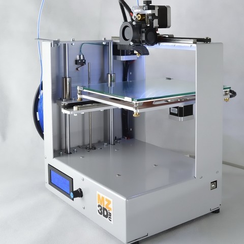
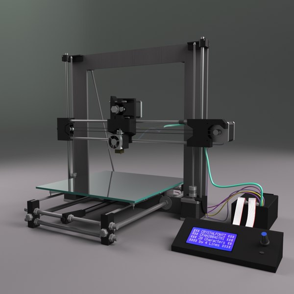
3D printers of any design always contain the same things: Axes and rails along which the elements of the printer move and motors with belts that set these elements in motion. In a classic printer design, there are at least 3 motors (one for each axis), 3 rails (one for each axis) and an electronics board that controls the motors. The latter can hardly be called part of the mechanics, but since it controls the engines, it also indirectly affects the quality of the model.
Printing defects due to mechanical problems
Before changing anything in the printer, you need to decide what exactly needs to be configured. Often defects are visible visually. Our blog has an article about most printing defects, which details the reasons for their occurrence. The following is a list of defects and what element of mechanics they are associated with:
-
Layer shifting - Belts, Motor current, Guides
-
Ringing - Guides, Speed
-
Incorrect model geometry - Guides, Motor steps, belts
As you can see, all the above problems do not interfere with the printing process itself, but the result leaves much to be desired. Sometimes mechanical errors can completely stop the printer from working. Therefore, it is better not to take the situation to extremes and, if any problems arise, immediately start checking and configuring the 3D printer.
How to save settings
To fix some defects, you need to change the printer software settings. Therefore, before adjusting the mechanics, it is necessary to understand how to properly store the settings inside the printer. There are 3 ways to do this:
All settings are located in the corresponding menu of the printer
Depending on your firmware, this manual will indicate code sections for MARLIN firmware in the configuration.h file
We first enter the parameters into the printer and then store them in EEPROM - the internal memory of the microcontroller. Or paste all the necessary settings at the beginning of GCODE. To learn how to do this, read our article on working with GCODE and creating macros.
To save to EEPROM, you need to send the printer a command to change some value (which can also be inserted into the initial GCODE), and then send the M500 command (save the current settings to permanent memory). The EEPROM function must be enabled in the firmware, for this you need to remove two slashes in the line:
//#define EEPROM_SETTINGS
Whichever option you choose, you should be careful when using any commands. You will not be able to harm the printer in any way when changing the settings, but if you make a mistake, you will have to look for the cause of possible further problems for a long time.
Setting Instructions
Now you can start setting up the printer itself. If you decide to set several parameters at once, then it is better to use the order of adjustments as in the article, since some of the settings are related to each other and if you use the wrong order, adjusting one element of the mechanics will override the settings of another element. For example, you should not adjust the motor steps before tightening the belts, as changing the length of the belts will change the "true" steps per millimeter of the motors. Also, before setting up, you must make sure that there are no backlashes in the printer frame, tighten all belts.
Belts
The first thing to start setting up the printer is the belts. They directly affect the geometry of the model and, when pulled too much, they cause a lot of problems: displacement of layers, changes in geometry, ripples. First you need to make sure the belt is intact. To do this, look at the entire belt, especially the areas where the belts bend. If the belt has outlived its usefulness, then you can see a section of the belt where the distance between the teeth has greatly increased and a metal wire (cord) is visible between them. This means that it's time to completely change the belt.
Broken belt with broken cords
If the belt is intact or you have already replaced it, then you can proceed to the next step. Depending on the design of your printer, you need to move the roller through which the belt passes. The tension should be such that the carriage or table moves effortlessly, but at the same time, when moving quickly, the belt should not slip the teeth on the motor gear.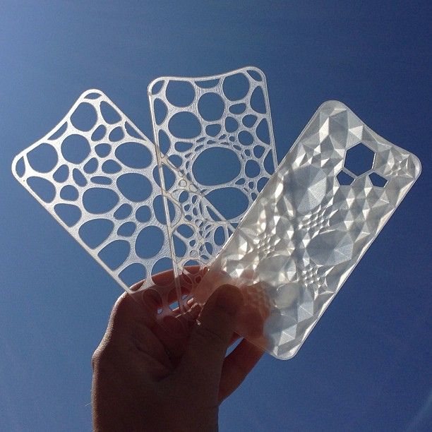 Adjust the tension of the belts on each axis of the printer using this method.
Tip: if your printer came with a belt tensioner in the form of a spring attached to the belt itself, remove it. Due to the flexibility of this tensioner, printing defects will occur, such as protruding corners on the model. It is better to adjust the belt without using this tensioner.
Belt tensioner
Current motors
As we know from the school physics course, the power of the engine depends on the voltage and current strength. Since the voltage on all printer electronics is the same everywhere, the only thing that can be changed is the current on the motor. More precisely, it should be said the maximum current that the driver will supply to the motors. To change this limit, you need to climb inside the case and find the printer board. On it you will see the printer driver. We are interested in a small potentiometer on the driver itself (in the picture below it is indicated as a tuning resistor).
Example of potentiometer location on driver
For adjustment, you will need a voltmeter and a small Phillips or flathead screwdriver. Before proceeding further, it is necessary to calculate the maximum current supplied to the motors. Different formulas are used for different drivers, the most popular ones will be listed in the table below:
| Driver name | Formula | Explanations |
| A4988 | Vref = Imax * 1.25 for R100 | To understand which formula to use, you need to find a resistor with the signature R100 or R050 on the driver. They are located next to the driver chip. |
| DRV8825 | Vref = Imax / 2 | |
| LV8729 | Vref = Imax / 2 | |
| TMC2208 TMC2100 TMC2130 | Vref = Imax * 1. | One formula for all drivers |
 41
41 The value of the maximum current (Imax) depends on the motor controlled by the driver. This can be found in the engine specification or on the sticker on it. The following are the currents for the most popular motor models:
17HS4401 - current 1.7 A
17HS8401 - current 1.8 A
17HS4402 - current 1.3 A
Substituting the value into the formula, we get the Vref value for the maximum current supplied to the motor. But at this value, the engine will get very hot, so the resulting Vref value must be multiplied by 0.7. For example, for a motor with a maximum current of 1.5 A and a TMC 2208 driver:
Vref=1.5*1.41*0.7=1.48V
Now the resulting value can be used when configuring on the printer itself. To do this, disconnect the wires going to the motors, turn on the printer and place one voltmeter probe in the center of the trimmer, and the second probe to the negative terminal on the power supply (you can also use the negative terminal on the printer board and the contact on the driver, labeled as GND). You will see some value on the voltmeter screen. Turn the trimmer clockwise to decrease the Vref value and counterclockwise to increase it.
Attention: you should not specify a Vref value higher than the maximum calculated for your engine! Otherwise, the engine will soon break down!
Once you have adjusted the value on the drivers, you can turn off the power to the printer, connect the motor wires, and put the case back together. This completes the driver setup.
Motor steps
When setting up motor steps, you will need a ruler. For convenience, you can use the program Repetier-Host. The adjustment for each of the three axes occurs according to the same algorithm:
-
Set the caret to zero coordinates (Autohome or G28)
-
Move the carriage some distance
-
We measure how far the carriage has traveled
-
We calculate the correct number of steps per millimeter using the formula:
True steps per millimeter = current steps per millimeter * reported distance / distance traveled
For example, if the printer was set to 100 steps/mm, we tell the printer to move 80mm and the printer travels 87. 5mm. Then the correct steps per millimeter would be 100 * 80 / 87.5 = 91.42 steps/mm. For the convenience of measurements, you can fix a ruler on the table, and a thin object, such as a needle or pin, on the carriage. Then it will be possible to accurately measure the distance traveled. The extruder uses a partially different algorithm to measure distance:
-
Inserting plastic into the extruder
-
Cut it right at the outlet
-
We give the printer a command to stretch the plastic a certain distance (at least 100 millimeters)
-
Cutting plastic again
-
We measure the length of the resulting piece of plastic
-
We use the formula from the previous algorithm
Next, the settings data must be inserted into the firmware in the line:
#define DEFAULT_AXIS_STEPS_PER_UNIT {X,Y,Z,E0}
X,Y,Z and E0 should be replaced by the steps per millimeter for each of the axes, respectively. Otherwise, you need to insert this line into the initial GCODE:
M92 Ennn Xnnn Ynnn Znnn
Instead of nnn in each of the parameters, you must substitute the steps per millimeter for each axis. If you want to adjust the steps only for not all axes, then you can remove unnecessary parameters.
Acceleration
This parameter is responsible for the rate of change of speed. That is, how fast the printer will change its speed. This affects the nature of the movement of the hot end relative to the table. If the acceleration is too small, then the printer will print slowly, if it is too large, then the outer surface of the model will have visual defects: fading waves will be visible near each of the corners, as in the picture below.
To set up acceleration, you need to follow simple steps:
-
Cut a model of a standard test cube with a wall thickness equal to one nozzle diameter, without filling and top layers, bottom 2-3 layers;
-
Open GCODE file in notepad;
-
Find the G28 command at the very beginning and insert the line data after it:
M201 X5000 Y5000
M204 P500 T500
-
Save the changes, print the model according to the received GCODE and note at what parameters P and T it was printed;
-
Open the same GCODE file and change the P and T values on the second line, adding 500 to each;
-
Repeat steps 4-5 at least 3 times;
As a result, you will get several test cubes, some of which will show waves at the corners. Choose the cube that is printed with the highest P and T parameters, but that no waves can be seen on it. The number in parameter P will be the desired acceleration value. To save this value, you need to find 2 lines in the firmware:
#define DEFAULT_MAX_ACCELERATION {X,Y,Z,E0}
#define DEFAULT_ACCELERATION {nnn}
Instead of X and Y, you should put an acceleration twice as high as found earlier. And instead of nnn, you need to put the acceleration value found earlier. Otherwise, you need to insert a line in the initial GCODE:
M204 Pnnn Tnnn
In the parameters P and T, you need to put the value of the found acceleration. After that, the acceleration setting can be considered complete.
Jerk
A jerk indicates the speed with which to start accelerating. It affects the model in a similar way as acceleration: it creates ripples around the corners of the model. But it also increases the protrusion of the corners if the jerk is too small. The jerk setting is also similar to the acceleration setting:
-
Cut a model of a standard test cube with a wall thickness equal to one nozzle diameter, without filling and top layers, bottom 2-3 layers.
-
Open GCODE file in notepad
-
Find the G28 command at the very beginning and insert the line data after it:
M205 X5 Y5
-
Save the changes, print the model according to the received GCODE and note at what X and Y parameters it was printed
-
Open the same GCODE file and change the X and Y values on the second line, adding 2 to each
-
Repeat steps 4-5 at least 3 times
As a result, you will get several cubes. Find a non-rippled cube printed at the highest X and Y settings. This will be the jerk value for your printer. To save them, you need to find the line in the firmware:
#define DEFAULT_XJERKnnn
#define DEFAULT_YJERKnnn
It is necessary to substitute the jerk values for the X and Y axes, respectively. Otherwise, you need to substitute the command in the starting GCODE:
M205
Instead of nnn, you need to substitute the jerk value found earlier. This completes the jerk setting.
Speed
In fact, there are many different speed parameters, the values \u200b\u200bof which vary greatly. Let's take a look at the main ones:
This parameter is responsible for moving the nozzle without extruding plastic. The value is in the range from 80 to 120 mm/s. Limited only by the maximum speed at which the motors can rotate. Does not affect the model
This speed is important because it indirectly affects the adhesion of the model to the table. Usually lies between 15 and 30 mm/s
-Print speed of inner walls
Usually set to about 60 mm/s, it only affects the strength of the model. Depends on the maximum amount of plastic that the extruder can push through the nozzle
-Speed of printing outer walls
Usually about half the printing speed of the inner walls (30 mm / s). It affects not only the strength of the model, but also the appearance: the lower this speed, the smoother the walls will be.
The standard value is 80 mm/s, it only affects the strength of the model
Usually set from 20 to 40 mm/s, the quality of the upper layer of the model depends on it: the lower the value, the smoother the cover.
All of the above parameters are selected experimentally. Usually there is a simple rule: higher speed - lower quality. Therefore, do not try to find the ideal value for all situations. It is better to find values for fast printing, quality printing, and an average that will be used for most models.
Check settings
The last step in setting any of the above parameters will be to check the result. If you have written parameters in firmware or saved them in EEPROM, you can use the M503 command. It will display all printer settings on the computer. To test the settings in practice, you can print several test models:
Classic Benchy
Simple calibration cube
Calibration cat
On each of the above models, defects will be clearly visible, if they still remain after the mechanics are adjusted.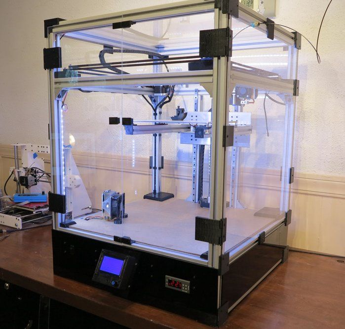
#Useful
Expert in the field of additive and subtractive technologies, 3D equipment and CNC machines with over 10 years of experience.
Share
all materials
Do you have any questions?
Our experts will help you with the choice of 3D equipment or accessories, consult on any questions.
Optimal Cura settings for PLA 3D printing
3DPrintStory 3D printing process Optimal Cura settings for 3D printing with PLA plastic
Through trial and error, you can gradually fine-tune your Cura settings for 3D printing with PLA (as well as many other 3D printing materials). The article below provides recommendations from personal experience that may be helpful if you are using PLA plastic on your 3D printer and Cura to slice and prepare your 3D print modes.
In addition to explaining preferred temperature settings, advanced support and infill settings are discussed in detail, as well as many other factors that affect 3D printing without defects and problems.
*** The following settings are for Cura and tested on Lulzbot TAZ 3D printers with an E3D host. We have successfully used these settings on our TAZ3 and TAZ5 printers as well as the HATCHBOX 3.0mm PLA. Simplify 3D uses very similar profiles.
3D print quality settings
3D print layer height is very dependent on your 3D printer's nozzle size as well as the quality you want to achieve. A 3D printer with a 0.6mm nozzle can achieve layer thicknesses of up to 0.4mm, and a part with a layer height of 0.1mm will take twice as long to produce as one with a 0.2mm nozzle, so these factors are important to consider.
Our default 3D print quality setting is 0.25mm layer height. Then we fine-tune the retract settings for the PLA. The resulting profile for Cura would be:
- Minimum Travel: 1.
 5mm
5mm - Enable Combing: All
- Minimal Extrusion Before Retracting: 0.005mm
- Z Hop When Retracting: .1mm
means "Combing" The printer follows the print path rather than trying to close gaps. This will help prevent "burrs" from appearing on the sides of the 3D model. "Z Hop" is set to 0.1mm when retracted, so thin sections of 3D models are less likely to be damaged.
When we click on the "Advanced Settings" tab in Cura, we look at the "Retraction" and "Quality" sections. We set the retraction speed to 10 mm/s and the distance to 1.5 mm. In the "Quality" menu in the "Advanced section" we do not increase the initial layer thickness, but increase the initial line width to 115%. We have found that this helps improve adhesion to the table without compromising the quality of the 3D print.
The figures below show examples of 3D printing. From left to right, 100 micron layer height (high quality), 250 micron layer height (standard quality), and 380 micron layer height (draft quality).
Infill settings
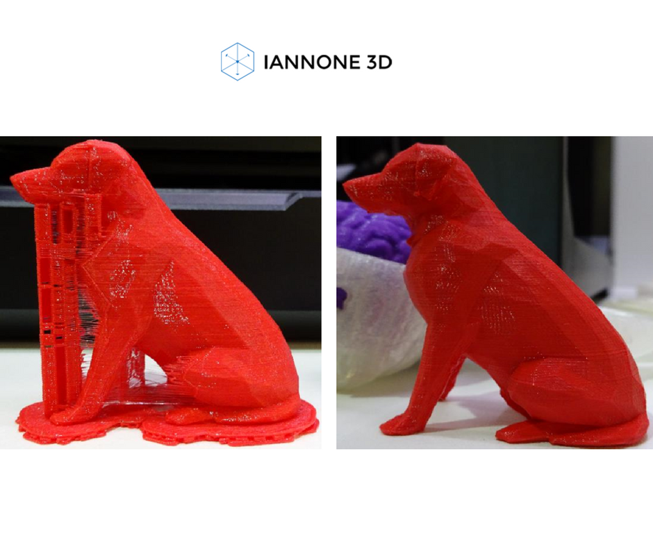
To get a clean PLA print, we always try to include at least 4 bottom/top layers (i.e. you have to multiply the layer height by at least 4). It can increase depending on how flat the object is, how high the fill density is set, and how thick your layer is. A long rectangular piece with a layer height of 0.1mm will require more than 10% infill and at least 7 bottom/top layers to avoid pitting. The print below had just such a problem: too little infill and too few bottom/top layers, spoiling the 3D print result.
The preferred infill density percentage is unique to your particular 3D model, as are the quality settings. Infill overlap settings are something to focus on to improve the surface quality of a 3D model.
This 3D model had 10% infill and 3 bottom/top layers at a layer height of 0.25mm which was not enough for a smooth top surface.
This 3D model had 20% infill and 5 bottom/top layers at a layer height of 0. 25mm, which was enough for a beautiful outer surface.
Infill Overlap
Infill Overlap refers to the percentage of infill overlap on the shells. When the number of shells is low and the percentage of infill overlap is set above 12%, we notice "veining" on the surface of finished 3D models, especially on large translucent PLA parts. We prefer almost all of our PLA models to have an 8% overlap. The photo below shows an example of two shells with a 15% overlap of translucent blue PLA. While the effect looks pretty cool, we needed to reduce the fill overlap to get this veining defect to disappear.
Speed and temperature
As we warned above, these PLA settings work well with E3D enabled Lulzbot TAZ printers. These temperatures (and speeds) may vary depending on the 3D printer and how long it has been used.
Our nozzle operates at a comfortable (but slightly higher than average) temperature of 205-210°C for PLA. We usually preheat the table to 60°C, but since we added a thicker 1/4 inch glass, we increased it to 65°C. This thicker glass makes the table process easier and also prevents cracks and chips. We've used PLA on tables that don't have a heating option, but it's definitely better to have a heated table. The glass stage heated to 65° helps prevent warping and prevents parts from being torn off during the 3D printing process.
We run our printers a little slower to ensure the best surface quality. We usually set our average speed to 60mm/s, with slower settings for the outer and top/bottom layers. In advanced mode we have the following speed settings:
- Travel Speed: 150 mm/s
- Bottom Layer Speed: 25 mm/s
- Infill Speed: 60 mm/s
- Top/Bottom Speed: 40 mm/s
- Outer Shell Speed: 40 mm/s
- Inner Shell Speed: 60mm/s
Support Material Settings
We found the support settings to be one of the hardest things to change. Each material requires a different infill percentage and angle. Each one also requires a unique distance from the 3D model for easy removal.
Anyone who has been typing long enough probably doesn't like working with caliper settings. Our recommendations for support material settings are as follows:
- Structure Type: Lines
- Overhang Angle for Support: 50°
- Fill Amount: 15%
- Distance X/Y: 0.8mm settings
- Distance Z: 0.16mm
Same section as support, you will also find a type of base to grip with the table. While "brim" settings are not usually needed for PLA parts, large 3D models can warp and narrow parts have a hard time sticking to the table without tipping over. In our PLA settings, this option is usually disabled by default, and we enable it manually for such special cases.
The problem with base coats, especially on PLA, is that they are difficult to remove. We've had parts where the edge is much harder to remove than the base backing material. This forced us to switch to the narrower "skirt" version instead of "brim".
With "None" selected as the first layer type, click "…" to see more options. Then we change the number of lines to 10-15, the initial distance to 0.01mm and the minimum length to 250mm. This allows the first layer to form only on the outside of the 3D model. Although the outer side will still require additional processing, this saves a lot of time removing margins from the inner thin parts of the 3D model.
Cooling
And finally, the last section on the advanced settings tab is the ability to activate the active cooling fan. The fan for PLA plastic should always be kept on. If you try to turn off the cooling fan, you may get unpleasant defects (for example, in the photo below).
The resulting cooling settings for Cura using PLA plastic are as follows:
- Fan Full on at Height: .5mm
- Speed Min: 35%
- Speed Max: 75%
- Minimum Speed: 10mm/s
- Cool Head Lift: off
Conclusions models require minor changes. Certain 3D printing angles may require your support settings to be slightly closer in the Z or X/Y axis.