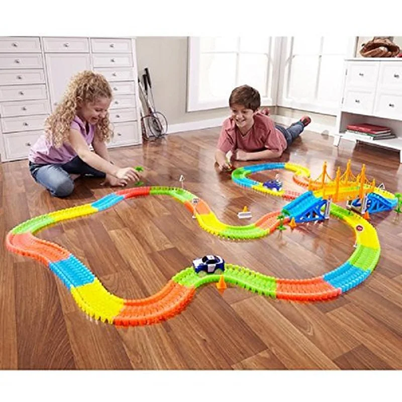
Magic tracks 3d print
▷ magic tracks 3d models 【 STLFinder 】
Magic Tracks Switch
thingiverse
Track switch for the original Magic Tracks. ... Differences to the original make: * Flat bottom for easier print * Correct dimensions
Magic Tracks Replacement Tire
thingiverse
This is a replacement tire for Magic Tracks cars. ... Must be printed in TPU, and it will be a snug fit!
Overpass for Magic Tracks
thingiverse
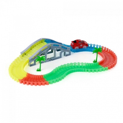
My son got a Magic Tracks set, which is a little battery powered car and some really nifty serpentine latching track. I made him an overpass.
I had originally envisioned connecting the ramps and the overpass together, and adding pegs to hold the...
Overpass for Magic Tracks
prusaprinters
I made him an overpass.I had originally envisioned connecting the ramps and the overpass together, and adding pegs to hold the track and stop it from slipping, but the slipping wasn't really an issue, and my son asked me to leave it like it is.It...
Magic Tracks trestle
thingiverse
My friend told me his kid lost one of the trestles to his magic Tracks set. I took measurements and made a (darn close) copy of it.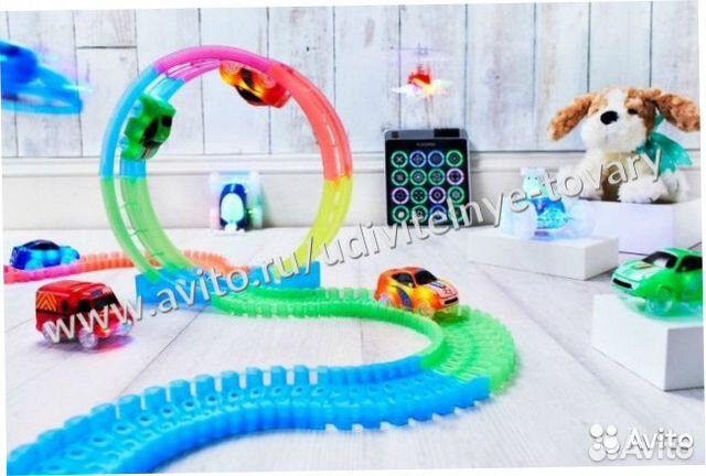 Its the dark gray one in the picture. ...I didn't put the round nubs on the top of the trestle since it should hold the...
Magic tracks croisement v1
thingiverse
Croisement pour Magic Tracks Crée par: DeadCatModifier par: Mr_Kiwixe Modification des bord du croisement ( les voiture sortaient du croisement). Modification du centre du croisement ( ajout de guide pour les roues).
Magic Tracks Crossover
thingiverse
**Edit: I've added a [new improved version](https://www.thingiverse.com/thing:3719607)** This is a 4 way cross over connector for magic tracks. It is can be hard to connect the first few times - make sure the brim has been fully removed (a craft. ..
..
Magic Tracks Crossover v3
thingiverse
This is an improvement of my Magic Tracks Crossover. Big thanks to djdc13 who [remixed](https://www.thingiverse.com/make:671642) my original and suggested some improvements. ... Improvements to this version: - raised the base so it is level and...
Magic tracks adapter
thingiverse
This is a magic tracks based part I created so i could make bridges and buildings that snap onto the track. Always nice to save someone else some work. that being said. it is not an exact replica. i wanted the piece to lock on not move like the rest...
Magic tracks to knex
thingiverse
I noticed a pretty massive lack of accessories for magic tracks. This part will let you use Knex pieces to flesh out the track a bit more. Everything is a pretty tight fit so you may have to run a few to find the right settings. If you would like me...
Magic Tracks Switch Repair Part
thingiverse
This is a repair part for Magic Tracks track switch. Made as 2 separate pieces for easy replacement. ... Printed in ABS on a CEL Robox 3D printer
Magic Tracks to Knex (Classic)
thingiverse
I remixed the design for the classic k'nex set. ... The fit is tight on both the Magic Tracks and K'nex side but it holds. ...
Magic Tracks to Duplo Adapter
thingiverse
This is a Magic Tracks (USA) connector with a 2x4 Duplo brick underside.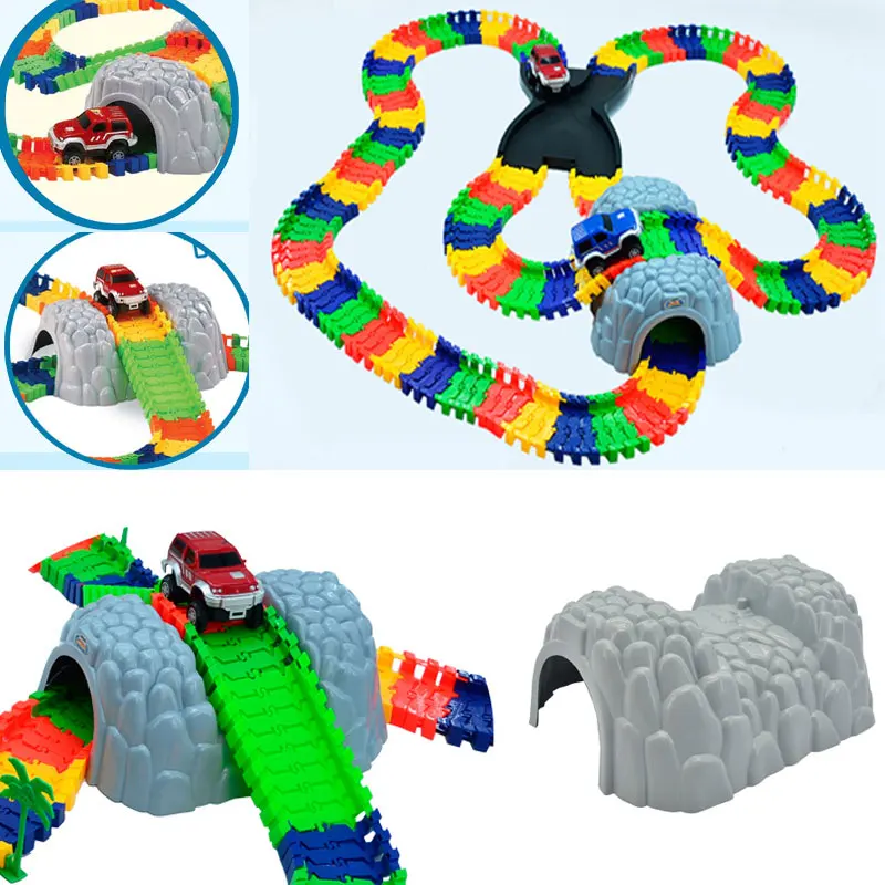 This is my first design! ...I'd never touched Meshmixer before today, so if you clock any rookie mistakes, please comment gently!
Magic tracks Theme Jurassic Park
thingiverse
Quelques accessoires pour circuit Magic Track sur le theme de Jurassic Park. Il est composé d'un porte de T-Rex qui sert de tunnel, une Porte d'entrée placé sur une mâchoire. En bonus un remix d'un Stégosaure élargi et modifié pour le rendre...
Magic Tracks - Aiguillage (Track Switch) Remix
thingiverse
... rail, I added a hole for a 3mm heated insert. I also used a M3x12mm socket cap screw (although you could use pretty much any length between M3x6mm - M3x16mm) Great addition to your magic tracks set. My boys absolutely love this track piece!
...
Magic Tracks Original to Chinese Adaptor
thingiverse
My son has the original magic tracks and for christmas 2019, we inadvertently purchased the "chinese" version off ebay, which is 80% scaled down version. So this thing allows the use of both. I included the individual pieces in case you want to...
Magic Tracks - Repaired Gear - Réparation engrenage
thingiverse
[Scroll down for English version] Engrenage pour réparation d'une voiture Magic Tracks, au cas où l'engrenage n'est plus pris sur l'axe et se met à tourner autour de l'axe, la voiture n'avance plus. L'engrenage de remplacement est celui en jaune sur...
Magic Tracks adapter
thingiverse
I found that a minor change was needed to interface w/ the track my kid has. ...No other changes were made.
Magic Tracks Overpass
thingiverse
This just fits on my FT-5(300mm work area) I printed it with one perimeter, and 5% infill with no top or bottom layers. I'll add a picture later, and an altered 3 piece design where the ascent and descent aren't as steep. ... ...
Magic Tracks adapter
prusaprinters
<p>I found that a minor change was needed to interface w/ the track my kid has. No other changes were made.</p> <p>Original design: <a href="https://www.thingiverse.com/thing:2085099">https://www.thingiverse.com/thing:2085099</a></p> <h4>Print...
Magic Tracks - Aiguillage
thingiverse
Thanks to NITROG1982 for the adapter, the most difficult part of this design.
Magic Tracks Switch Repair Part
thingiverse
This thing was made with Tinkercad. ...Edit it online https://www.tinkercad.com/things/hS9T4odWqa6
Cliff of Chaos - Magic Tracks, Neo Tracks, etc
thingiverse
The cliffs require support for the section that the magic tracks connect to. No other support is required for the other pieces.
I did swap out filaments when I printed the pillars. Pause the height at 8.0 mm if you would like to change...
Overpass for Magic Tracks - easy print
thingiverse
The original overpass uses way too much filament. I cut out some large chunks of the models for a quicker print. I've split the main part into two pieces with pins that connect for easy glueing. Note that you may need to print at 105% scale - I...
Super Splash! - Compatible with Magic Tracks, Mindscope Neo Tracks, Twister Tracks, etc
thingiverse
The Super Splash model works great on its own or as an addition to the Offroad Overpass model I made here: https://www. thingiverse.com/thing:2368955 Video: https://youtu.be/TNb9T24AdMc The model is compatible with Magic Tracks, Neo Tracks, and...
Super Splash! - Compatible with Magic Tracks, Mindscope Neo Tracks, Twister Tracks, etc
myminifactory
Video: https://youtu.be/TNb9T24AdMc The model is compatible with Magic Tracks, Neo Tracks, and anything else compatible with these. I have a variety of cars from different sets that all work with the model. The track connector with lowered parts is...
Pirate Ship Seesaw for Magic Tracks, Neo Tracks, and everything compatible
myminifactory
. .. side. I have not tested to see if this is too much weight for the seesaw to function normally.
Supports are required for all parts, but very little is necessary.
Works with Magic Tracks, Neo Tracks, and anything else compatible with these.
Pirate Ship Seesaw for Magic Tracks, Neo Tracks, and everything compatible
thingiverse
... I have not tested to see if this is too much weight for the seesaw to function normally. Supports are required for all parts, but very little is necessary. Works with Magic Tracks, Neo Tracks, and anything else compatible with these. ...
Bumpy Road for Magic Tracks, Neo Tracks, and more!
thingiverse
This is an addition to the Super Splash and Offroad Overpass models listed below:
https://www. thingiverse.com/thing:2385043
https://www.thingiverse.com/thing:2368955
View different cars driving on the bumpy road here:
...
Off-Road Overpass - Compatible with Magic Tracks, Mindscope Neo Tracks, Twister Tracks etc.
thingiverse
Welcome to my Off-road Overpass model! Many brave filament sacrificed themselves to bring you this model. They were slain by lack of experience and much trial-and-error. Watch it in action here https://youtu.be/wJ7Sy4n2LJU or up above. ...
Magic Track - Etsy.de
Etsy is no longer supporting older versions of your web browser in order to ensure that user data remains secure. Please update to the latest version.
Take full advantage of our site features by enabling JavaScript.
Find something memorable, join a community doing good.
( 898 relevant results, with Ads Sellers looking to grow their business and reach more interested buyers can use Etsy’s advertising platform to promote their items. You’ll see ad results based on factors like relevancy, and the amount sellers pay per click. Learn more. )
Non-motorized treadmill.
 3D printing is a high-tech tool in the industry.
 This article tells how 3D printing technology helps to bring even very complex and modern projects to life at minimal cost. And make the project serial!
The material provides examples of solving difficult issues that arise when creating new equipment, where 3D printing is practically the only way to implement the product.
Casting, bending, punching, milling, plasma cutting, laser cutting... without these technologies it is no longer possible to imagine the world of today's industrial production. Now 3D printing technology can be confidently put in this row, it harmoniously complements the set of modern production, allows you to produce complex, durable and reliable products from a wide range of materials. Well, okay, we can talk about this technology for a long time, let's move on to the topic.
This story begins in the spring of 2017.
There was an idea to create a Russian fully autonomous treadmill, an analogue of eminent overseas competitors, only with additional functionality.
We started by looking at the most popular models available on the market.
After studying it, we decided that the task was feasible in principle and decided to start designing and assembling a layout.
A cool design was developed, in fact, dozens of different options were worked out. We then adapted it to the production techniques at our disposal, which also had an impressive impact on the final look of the track.
[IMG ID=205954 WIDTH=474 HEIGHT=229][IMG ID=205953 WIDTH=122 HEIGHT=239]
The track has a built-in generator, an electronic system for regulating the force on the canvas for power loads on the legs, special double handles for extended set of exercises, wireless control from our own application with the ability to save results, statistics, load profile management.
If everything was more or less clear in terms of iron parts and mechanics, then there was a problem with all sorts of rubber bands, plugs, decor.
The fact is that the tracks of this type are equipped with canvases consisting of a set of aluminum profiles coated with a layer of polyurethane, and there are 60 such steps. Moreover, the steps must have an original tread pattern, it is desirable to have a brand logo. With rugs on the sides of the track such a picture.
All these parts must have a unique design. Despite the fact that this is also a mock-up sample, and in principle the product itself is not mass-produced, the parts should not have an expensive cost.
Initially, we wanted to order all the details on the side ...
After talking with various companies about the manufacture of rubber-coated steps with a unique design, we came to the conclusion that the project was becoming absolutely uncompetitive, not within the budget, because the cost of only one treadmill the canvas is obtained at half the cost of the entire track, and according to calculations, it should be no more than 25%.
They began to think about what to do ... We studied the Internet for self-manufacturing of polyurethane products ... Then the idea arose of 3D printing parts and pouring polyurethane into silicone molds.
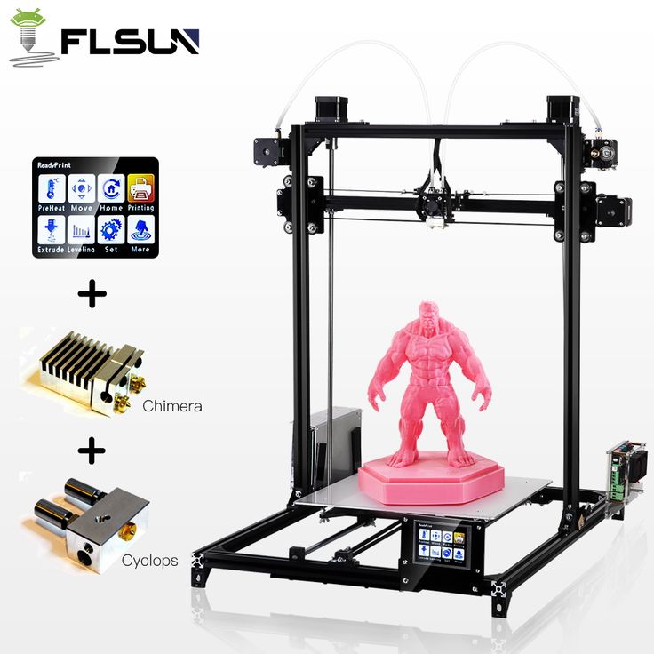
A Russian-made 3D printer was purchased, since only it had a decent working area at its cost + a closed case was important, since the parts were needed from ABS plastic.
After the first test prints, the full power of the technology available to us became clear!
Many parts originally planned in metal can be replaced with plastic, reducing weight and cost! Web pulleys, plugs, cases, holders, decor - everything was printed on a 3D printer!
Large parts were printed with a 1.0 mm nozzle and a 0.5-0.6 mm layer, small parts were mostly printed with a 0.5 mm layer of 0.2, and sometimes a 0.3 mm nozzle and a 0.1 mm layer were used for master models.
Plugs for pipes and screw heads
Exterior decoration element, printed with gold plastic, then painted in gold paint
Timing pulley for polyurethane belt with metal insert for key. The combination of strength and weight and price!
[IMG ID=205927 WIDTH=396 HEIGHT=222][IMG ID=205904 WIDTH=394 HEIGHT=221]
By the way, about the weight of the same pulleys, unlike casting, 3D printing allows you to adjust the percentage of filling the insides of the part, so the weight of the part can be significantly reduced compared to casting from a similar material, if it is suitable for loads.
[IMG ID=205975 WIDTH=381 HEIGHT=214]
The first version of the shafts - shafts with cast pulleys, then it was abandoned due to technological difficulties and cost compared to simply printed axle shafts
The second version of the shafts with printed pulleys, or rather semiaxes - the best option turned out to be both in terms of ease of manufacture and price
To create the steps of the web, a master model of the future rubber component was printed.
Next, silicone molds and the necessary tooling for centering the position of the metal base in the mold are made.
[IMG ID=205899 WIDTH=400 HEIGHT=575][IMG ID=205906 WIDTH=324 HEIGHT=575]
It was cast immediately 9 steps at a time from domestic polyurethane with the addition of black pigment. In total, 60 steps are needed for one canvas!
It is very important in this process to observe the technology when pouring, in case of violation of it, not very pleasant things happened in the form of incomplete drying of the product, excessive bubbling, soiling when it was touched.
After making the steps, the canvas was assembled. Despite its impressive weight, it spins very easily!
Then the question arose of making decorative rugs on the sides of the track. A master model was assembled from 5 separate parts, processed, painted to give the necessary texture. On its basis, a mold for pouring was cast, and then the rugs themselves were cast.
[IMG ID=205898 WIDTH=264 HEIGHT=598][IMG ID=205900 WIDTH=339 HEIGHT=600]
The track was controlled using a standard monitor developed by us, or a smartphone with an application.
Computer monitor project
Machining the back cover of the monitor
Board installed in the case
Serial monitors complete!
Monitor on a treadmill
For the first version of the monitor, we designed and assembled the control board of a custom-made control panel for us. We printed out the case, processed it and assembled the monitor. A couple of cases were made glossy, for which they had to be polished very carefully. Next came the matte versions.
As a result, we got just such a beauty. There is still work to be done, but overall it turned out great!
And this whole project was made possible largely thanks to 3D printing technology, thanks to which we were able to produce almost all plastic, rubber parts ourselves, which allowed us to fit into the budget.
Moreover, with the help of 3D printing, you can relatively quickly and inexpensively change the design of the project, for example, at the request of the customer, brand the simulator even for a certain gym!
At the moment we are professionally engaged in 3D printing, we produce our own Nephila 3D printer, since our projects often require large parts made of ABS plastic, and printers available on the market with similar parameters have a very decent price tag, although there is nothing magical about them.
3d printing problem. Elephant foot
3DPrintStory 3D printing process 3d printing problem. elephant leg
Hello everyone. Today we will touch on a fairly common, but somehow too little mentioned topic. This is elephant foot . One way or another, everyone has come across this, but most people simply give up on this problem, because they don’t know how to solve it and simply cut this deformation with a knife. But this is clearly wrong, so today I will tell you how to fix this whole thing, since it is quite simple.
First, let's look at why this deformation occurs at all. There are two options:
The table temperature is too high. Because of it, the model simply melts and the lower layers spread a little. This is solved by lowering the temperature of the table.
The second one is trickier and not so obvious, so here are some funny pictures for you. Conventionally, the plastic tracks are flattened when printing at the most common settings. Namely, at a layer height equal to half of the nozzle diameter. If everything happens as in the picture, then everything is fine and the tracks touch each other a little, holding the model together. In this case, the geometry will be perfect.
| |
But let's see what happens if the distance from the nozzle is less than the layer thickness. There is the same amount of extruded plastic, but it has nowhere to go and the width of the tracks will increase. At the same time, neither the 3d printer nor the slicer knows about this and they will not correct the distance between the tracks, so the tracks will conflict with each other.
Here the intersection is shown in red. Naturally, this cannot be so, and the paths merge into a shapeless mess, mixing, spreading and forming ridges. Here I showed it very conditionally, but for understanding the processes it will do. If you look closely, you can see that these ridges and streaks go beyond the upper boundary of the layer and occupy part of the space under the next one. Naturally, he also cannot lay down as planned, as a result, the pattern repeats, albeit on a slightly smaller scale, again and again, until the ridge is no longer so small that their presence can be said not to affect the next layer and the model starts to print normally.
It also happens when the elephant leg ends with the layers of the bottom, which have one hundred percent filling. This case is the same eggs, side view, just the paths can spread as wide as they like and do not create ridges and, accordingly, do not affect the next layers.
So, when it is clear why this elephant's leg arises, we can safely offer three solutions.
- Increase the distance between the nozzle and the table on the first layer to match the one specified in the print settings.
- Decrease the feed on the first layer so that the tracks do not sprawl or conflict.
- Tell the slicer how wide the track actually turns out so that he builds them into an even model.
Of course, the first option is the most correct and it can be implemented either through table calibration, which is quite laborious, or through setting the z offset in the print settings. This is an extremely useful setting in all popular slicers. In Cura she is in section sticking to the table, in simplify 3d on the g-code tab. It works very simply - it adds its value to all z coordinates in the model, or subtracts it if it is written with a minus. Therefore, if we have an elephant's leg, then we slightly increase this parameter until the moment when it does not pass.
I printed some calibration cubes to show how this setting works. In addition to him, nothing has changed not in the model, not in the settings. The first cube is printed with a z indent of 0, followed by 0.05 mm increments.
By the way, the same parameter can be used if the table is calibrated with too much clearance and the plastic does not stick. Just set it to a negative value.
The second method, I think, is not particularly correct, since with it the first layer is lower than necessary for the model. But in reality this can be neglected. The essence of the setup here will be - the creation of two different processes - one for the first layer with a lower feed, the other for the rest of the model. This is rather tedious compared to the indent setting, but nevertheless it has the right to exist in case for some reason it cannot be applied. I will explain using simply 3d as an example. First, we create a process for the first layer, reduce the flow value by, say, 20 percent, after which we go to the advanced tab and set it to stop printing at height equal to the layer thickness from the settings. In our case, 0.2. Next, we create another process with a normal flow and set the advanced tab to start printing at height, which is also equal to the layer height. That's it, there are two processes that together will cover the entire model, but have different settings. In our case, a different flow. Now we need to print some small test models and see. If there is an elephant leg, reduce it further, if not, stop or even slightly raise it in order to more accurately determine the ideal setting.
The third method, unfortunately, will not help if the elephant's leg is too large, but it works very well with a medium or small one. The point is to play around with the extrusion width settings of the first layer. By the way, many people think that if the value of this setting is reduced, then the tracks will become narrower, but in fact the opposite is true. In fact, this is not a control parameter, but a controlled parameter, that is, it is necessary to output to it what is actually obtained, and not what we want to receive. If we have a nozzle of 0.4 mm and the extrusion width is also 0.4 mm, and the tracks on the first layer of the clavicle are twice as wide, that is, 0.8, then we set the extrusion width of the first layer to 200 percent, that is, 0.8 divided by 0.4. As a result, the slicer itself will push the tracks apart so that, firstly, they line up on a flat surface along the outer perimeter, and secondly, they do not conflict with each other and, accordingly, do not bulge. In this case, the resolution of the first layer will be lower, as if printed with a nozzle with a larger diameter, but the plastic will be squeezed into the table, which in some situations can increase adhesion.