Led strip 3d printer
How to Add LED Lights to Your 3D Printer
The success of a 3D print depends on the integrity of the first layer. But just a bit of plastic oozing out of the nozzle can ruin everything. Not everyone can afford a printer equipped with servo-assisted nozzle wipe routines to get around this problem, but you can still spare a few minutes to manually babysit the first layer.
Good lighting, however, is the bare minimum requirement for that purpose. And incorporating it in your existing 3D printer is cheaper and easier than you think. Here’s how you can upgrade your printer with slick LED lighting to improve first-layer visibility.
Tools and Materials Required
In addition to a 3D printer, you will have to make sure you have these tools and materials ready before diving into this project. Since this guide offers options in terms of skills, tools, and materials required, the requirements are split into the mandatory and optional categories.
Most of the items listed are commonly found in a typical household, but you may need to purchase some of these. Although you can buy the mandatory items right away, please read through the guide once to figure out which one of the optional items you already have and make a note of those that you may need to procure.
Nothing is as frustrating as finding out you have a critical tool or component missing in the middle of a build.
Items You Absolutely Need
- 3D printer.
- SMD LED strip.
- Scissors.
- 3D printing filament (PLA, PETG, or ABS).
- Hookup wire (gauge varies according to voltage chosen).
- Wire stripper (recommended) or sharp blade.
- M3 T-slot nut (drop-in type recommended).
- 6mm M3 button head cap screw and compatible screwdriver.
Optional Items
- Phillips head screwdriver (standard sizes: #1 or #2).
- Solderless LED strip-to-wire connectors.
- Soldering kit.
- Heat-shrink tubing (10mm).
- Heat gun or lighter.
- Ring or fork insulated terminals.
- Insulated terminal crimping tool.
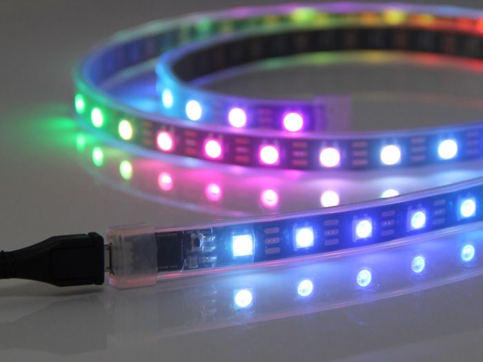
Related: How to Use RGB LED Strips to Light Up Your Life
Step 1: Figuring Out LED Strip Placement
For the majority of 3D printers sporting the Prusa/Mendel bed-flinger design, such as the Prusa i3 or Creality Ender 3, there’s only one optimal location where you can install the LED strips. And that’s on the underside of the aluminum extrusion acting as the cross-member between the pair of Z-axis extrusions.
Installing the LED strip in this location will not interfere with your 3D printer’s motion system, while shining light directly down onto the build surface. The vertical Z-axis extrusions also serve as a convenient means to route any wires safely without fouling with the motion components such as linear rails or V-slot wheels.
Step 2: Download and Print the LED Strip Holder
Using the adhesive backing on the LED strip to attach it anywhere on the printer is a risky proposition.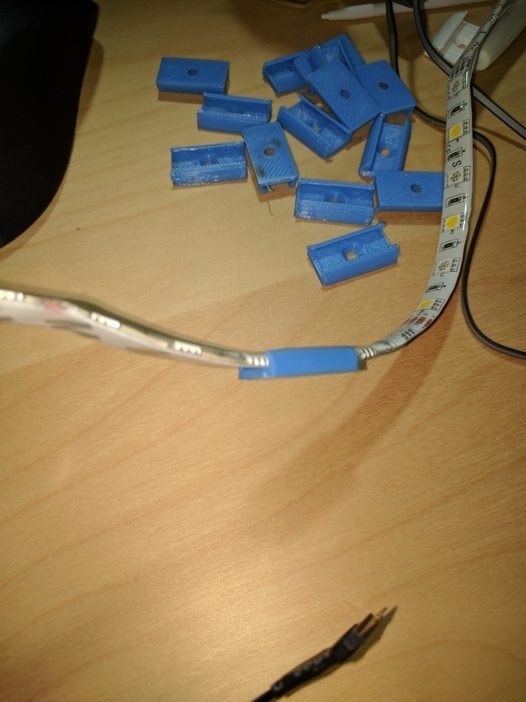 Adhesives may fail over time, which can cause the LED strip come loose and fall into the motion components. That’s a recipe for electrical shorts and subsequent fires.
It’s safer to download and print an LED strip holder for Creality Ender 3, Prusa i3, Voron, or any other printers off free 3D model repositories such as Thingiverse or Thangs. You might also want to 3D print cable covers to organize cables out of the way.
It’s possible to increase or decrease the length of these cable covers in the slicer software to fit the exact dimensions of your printer.
Step 3: Choosing the Right LED Strip Type
SMD LED strips are available in a wide array of options, but getting the voltage rating right is of the utmost importance. The LED strips are typically available in 5V, 12V, and 24V options, with the choice depending on the operating DC voltage output supplied by your 3D printer’s power supply unit (PSU).
There are a couple of ways to ascertain the DC voltage supplied by the PSU.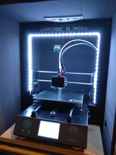 You can either get the information off the product page on the printer manufacturer’s website, or you can refer to the manual. In the worst-case scenario, you can physically check the compliance label on the PSU to figure out the DC output voltage.
SMD LED strips are also available in various color configurations. Single-color cold or warm white LEDs (bearing positive and negative terminals) are ideal for the purpose of illumination over RGB LED strips. You can also opt for high-density LED strips packing in more LEDs per meter for brighter illumination at the cost of higher power consumption.
Step 4: Wire Sizing Calculation
The thickness of the wire used to power the LED strips is directly proportional to the maximum current drawn. It is fine to use thicker wires than needed, but thinner wires tend to overheat and cause voltage drops.
Calculating the maximum current drawn by the LEDs is a good way to optimize wire thickness. This is done by dividing the power rating of the LED strip by its operating voltage.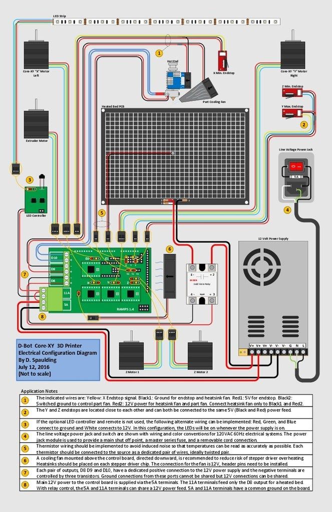 For example, if the LED strip is rated at 24 watts per meter and you are using half a meter, the power consumption of your LED strip is 12 watts.
For 24V LED strips, the maximum current drawn would come out at 0.5 amp. At half the voltage, 12V LEDs require twice the current, which works out at 1 amp. Finally, 5V LED strips would require a substantial 2.4 amps. This handy JST DC wire-sizing chart should help you choose optimal wire size for your particular LED strip.
Step 5: Cut the LED Strip to Size
Cut the LED strip to size as per the fitting requirements of the 3D-printed holder of your choosing. Be sure to cut the LED strip only where exposed copper pads/terminals are visible. This is marked with a scissor icon on most LED strips.
Step 6: Prepare the Hookup Wires
The length of the wire should be sufficient to bridge the gap between your 3D printer PSU and the LED strip. It’s safer to keep a margin of error and oversize the wire. You can always cut it down to size later.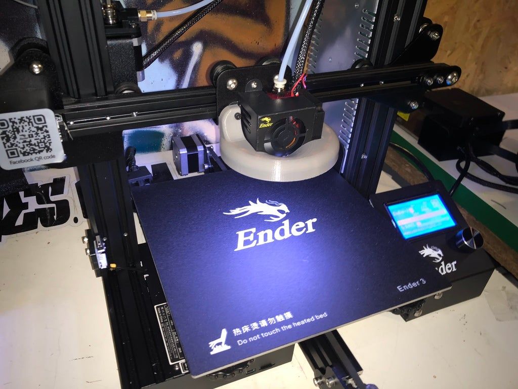
Using either dedicated wire strippers or a sharp blade, expose about an eighth of an inch of the red and black hookup wires.
Related: Understanding the Basics To Succeed at Soldering
Step 7: Wire Up the LED Strip
If you know your way around a soldering iron, proceed to solder the red and black wires to the positive and negative terminals, respectively, on the LED strip. Top that off by using either a lighter or heat gun to insulate the exposed solder joints with heat-shrink tubing.
If soldering isn’t your cup of tea, solderless LED strip-to-wire connectors allow you to do the same without requiring any tools. Just be sure to get the polarity of the wiring right. The red wire goes to the positive terminal and black to negative.
Step 8: Install LED Strip in 3D-Printed Housing
LED strips usually come with adhesive backing. Use that to fix the LED strip in the 3D-printed holder.
Now would be a good time to ensure that your 3D printer is powered off and disconnected from the power outlet.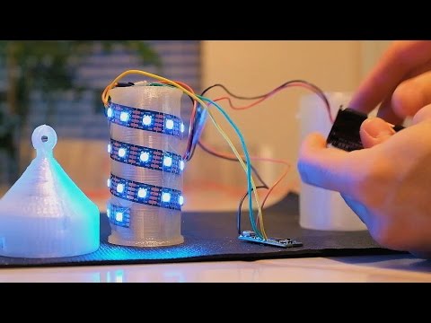 Remove the mains cable from the power inlet socket on the printer to be absolutely sure.
Step 9: Mount Housing to 3D Printer
Unless you fancy taking your 3D printer apart, it is recommended to use drop-in M3 T-slot nuts to install the LED strip assembly onto the printer. Depending on the type of T-slot nuts chosen, they can either be dropped straight into the aluminum extrusion, or dropped and then turned clockwise to lock them in place.
Once the T-slot nuts are in place, align the corresponding holes on the LED strip holder and secure them into the T-slot nuts using M3 button-head cap screws.
Step 10: Crimp Remaining Ends of Wires
Use the wire strippers to expose the remaining free ends of the red and black wires. The insulated terminal crimping tool will come in handy to crimp either ring or fork terminals onto the wires.
Although it is tempting to shove the stranded wires into the screw terminals without crimping insulated terminals onto their ends, doing so introduces the risk of loose connections and shorting.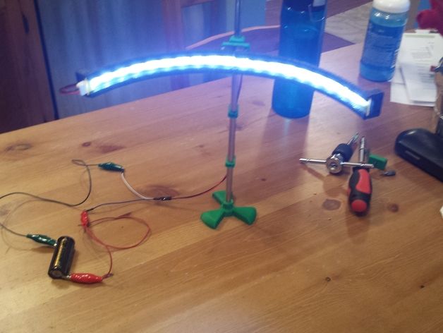
Related: Stunning DIY LED Projects To Try This Summer
Step 11: Connect LED Strip to PSU
Refer to your 3D printer’s manual to locate the PSU and expose the terminal block. It bears screw terminals for AC input and DC output. The AC input terminals (marked by symbols L, N, and G) should already be populated with the mains input wires. These shouldn’t be tinkered with at any cost.
The DC side of the terminal blocks is marked by + and - symbols signifying the positive and negative terminals. Hook up the red wire to the positive terminal and the black wire to the negative terminal. Reinstall the PSU in its correct place.
Step 12: Cable Management
Route the wires into the aluminum extrusion channels in such a way that they don’t interfere with the V-slot wheels, linear rails, or any other motion system components. Use the 3D-printed cable covers to secure the wiring into place.
Move all printer axes from end to end a few times to ensure that everything moves freely without hitting the LED strip, wires, or the cable covers.
Do a Test Run
With one hand on the power switch, and ready to kill the mains power supply at a moment’s notice, switch on the 3D printer. Your LED strip should light up the build surface if everything went according to plan.
Add LED Lights to Your 3D Printer: Success!
By following the step-by-step instructions, you will have now added an LED strip to your 3D printer to light up the build surface so you can achieve a perfect first layer.
Light Up Your 3D Printer's Bed
Introduction
Are you 3D printing in a room at night with barely any light? That's the problem that I came across when inspecting prints at SparkFun during odd hours. The light source behind me created a shadow over the print bed making it hard to see what was going on. In this tutorial, we will be using a LED strip to light up the print bed on a LulzBot 3D printer!
Required Materials
Note: This tutorial uses non-addressable LED strips but you could also customize your lighting by using an addressable LED strip of your choice.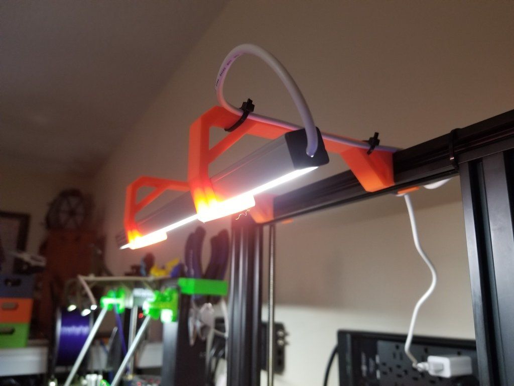 This will require additional components to get started.
To follow along with this tutorial, you will need the following materials. You may not need everything though depending on what you have. Add it to your cart, read through the guide, and adjust the cart as necessary.
Tools
You will need a screw driver, wire strippers, and diagonal cutters.
You Will Also Need
In addition to the materials listed above, you will need:
- Electrical Tape
- Hot Glue Gun and Glue Sticks
Hardware Hookup
⚡ Note: While the LED strip is labeled 12V, a 9V power supply was used so that the LEDs were not overwhelmingly bright. At 9V, it also did not dissipate as much heat.
The wiring is simple between the female barrel jack adapter and the non-addressable LED strip. Simply insert the black wire connecting the "12V"" pin to the "+"" of the barrel jack adapter's screw terminal. Then insert the rest of the wires to the "--" screw terminal.
Click the image for a closer look.
Note: When testing the non-addressable LED strip, the pin labeled "G" was actually blue and the "B" was actually green. Depending on the manufacturer, the label may vary. Try testing the LED strip out with a power supply to determine see if the letter represents the color.
Hookup Table
Below is a hookup table that shows the connection between the female barrel jack adapter and non-addressable RGB LED strip.
| Nonaddressable RGB LED Strip Pinout | Female DC Barrel Jack Adapter |
|---|---|
| + | 12V |
| - | G |
| - | R |
| - | B |
Connecting and Modifying the LED Strip
Note: This tutorial was written with the Taz 5 3D printer. However, you can use this as a guide to attach any type of LED strip to your 3D printer! You will just need to adjust the length as necessary depending on the size of your 3D printer frame and the density of LEDs on your strip.
We will be attaching the LEDs to the top of the frame. Make sure that the LEDs and wires are not in the way of any moving parts. Determine the length that you need by holding the LED strip up against the 3D printer's frame. The length depends on the size of your printer's frame. For the Lulzbot TAZ 3D printers, about 16x segments of the LED strip was used. For the Lulzbot Mini, about 12x segments seemed to be sufficient. Each segment consists of 3x LEDs between the exposed copper pads.
Click the image for a closer look.
Cut 4x segments off one end of the 1M non-addressable LED using the diagonal cutter. Relative to the 3D printer that I was using, I decided to remove the 4x segments from the right side of the LED strip.
Carefully strip extra wire insulation to expose more wire for the screw terminal. You may need to tin the tips of the wires by adding more solder. Then, insert the wires for R, G, and B, into barrel jack adapter's screw terminal labeled as "--". Then tighten the screw with a Phillips head screw driver. Repeat for the black wire labeled as 12V on the "+" side.
Pull gently to verify that the wires are secure in the socket.
Insulate the exposed end of the LED strip with hot glue.
Connect a barrel jack power switch between barrel jack adapter and power supply.
Testing
Now would be a good time to check if the hardware was wired properly. Connect the power supply to a wall outlet. If the LEDs do not light up, flip the switch to the other side to see if the LED strip lights up.
Secure the LEDs
Attach the LED strip flush against the top of the 3D printer's frame and ensure that the wires are not in the way of the printable area.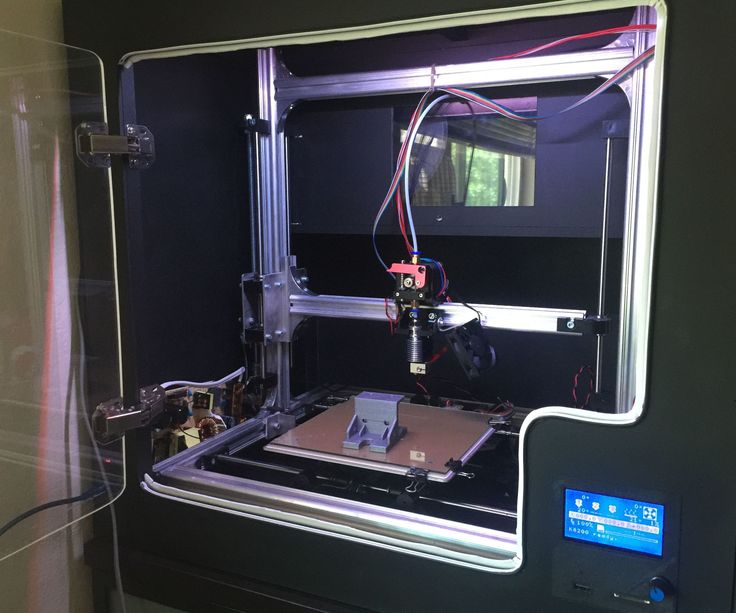 Since we want to illuminate the print bed, aim the LEDs toward the printer. While we could use the 3M adhesive that is on the back of the LED strip's clear jacket, I wanted to ensure that the adhesive did not fail during a print. Instead, the wires were secured by using electrical tape and wrapping the strip against the frame. Depending on the width of the tape, you may want to cut it down to prevent the LEDs from being blocked. You could use zip ties as well.
Tape was added as necessary on the enclosure; left, top, and right side of the frame as shown in the image below. Feel free to mount the power switch to another location so that you do not accidentally turn the power off to your 3D printer.
| Hightlighted Areas with Electrical Tape | LED Strip Mounted to 3D Printer |
Enjoy 3D Printing in the Light!
Insert the power supply into a wall outlet and flip the switch to power the lights when you need to check on your print!
Making It Better
Like all projects, you can always make it better and build upon the design.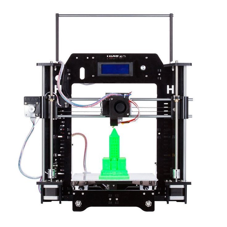 Here are few ideas to make it even more impressive by adding effects or interactive!
- Add microcontroller and transistors to control each color with the press of a button to add an effect.
SparkFun RedBoard - Programmed with Arduino
In stock DEV-13975
$21.50
49
Favorited Favorite 88
Wish List
Multicolor Buttons - 4-pack
In stock PRT-14460
Favorited Favorite 19
Wish List
N-Channel MOSFET 60V 30A
In stock COM-10213
4
Favorited Favorite 49
Wish List
Resistor 10k Ohm 1/6th Watt PTH
Retired COM-08374
Retired
Favorited Favorite 3
Wish List
- Add a motion or heat sensor to light up and change color indicating the print is finished.

SparkFun Grid-EYE Infrared Array Breakout - AMG8833 (Qwiic)
In stock SEN-14607
$45.95
2
Favorited Favorite 28
Wish List
SparkFun OpenPIR
In stock SEN-13968
$17.50
6
Favorited Favorite 29
Wish List
- Instead of RGB, use cool white for a more natural white.
 Mixing red, green, and blue may produce a "white light" but it is not a pure white.
 LED - 3W Aluminum PCB (5 Pack, Cool White)
In stock COM-13105
4
Favorited Favorite 15
Wish List
White Tri-Color LED Strip - Addressable, Sealed (1m)
Retired COM-13898
2 Retired
Favorited Favorite 4
Wish List
Resources and Going Further
Need some inspiration for your next project? Check out some of these related tutorials for ideas:
Using the Serial 7-Segment Display
How to quickly and easily set up the Serial 7-Segment Display and the Serial 7-Segment Display Shield.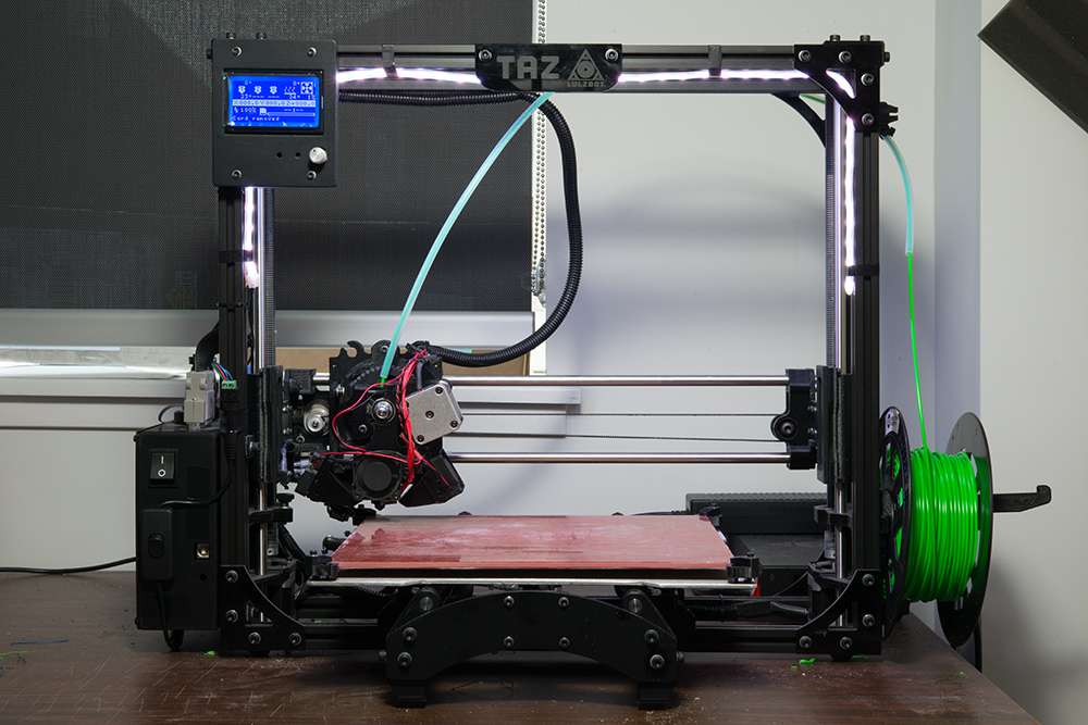
Favorited Favorite 14
Quick Illuminated Boxes
A quick tutorial to show you how to add LEDs to gift or holiday bags or boxes.
Favorited Favorite 5
Using Artnet DMX and the ESP32 to Drive Pixels
In this tutorial, we'll find out how to use Resolume Arena, a popular video jockey software, to control custom-made ArtNet DMX fixtures.
Favorited Favorite 10
SparkFun gator:particle Hookup Guide
The gator:particle is an I2C heart-rate monitor and pulse oximeter that can be used as a particle sensor. This tutorial will get you started using the gator:particle with the micro:bit platform.
Favorited Favorite 0
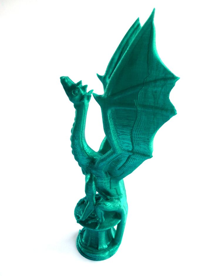
3D printer backlight.
 Variants and implementation
 3DPrintStory Reviews 3D printer backlight. Variants and implementation
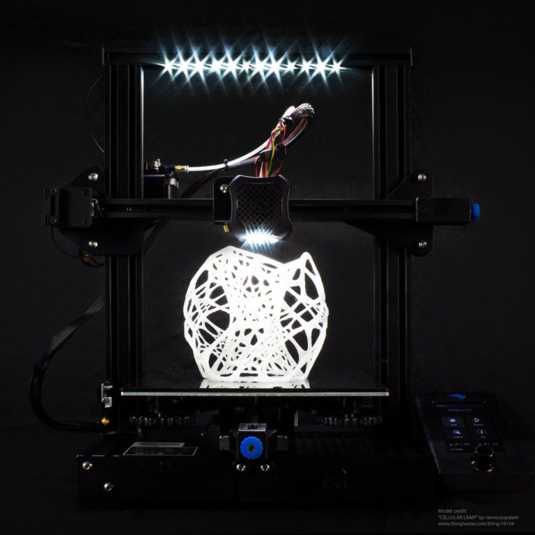
Have you ever got up in the middle of the night to check on the progress of 3D printing and frantically illuminated with a flashlight from your mobile? Or do you want your 3D printer to look cooler in the dark? The backlight can illuminate the entire 3D printer, workspace, or even the printhead, so there's room for your creative choices.
In addition to aesthetics and better visibility, another benefit of proper lighting is the accuracy when using a webcam, which is essential for programs like The Spaghetti Detective to track 3D print failures.
In this article, we'll look at several different lighting options for your 3D printer, print head, or entire desktop. However, before we present these options, let's discuss some of the specifics of your lighting setup.
What to look for when choosing a 3D printer light
There are several factors to consider when deciding which 3D printer light is best for you.
- Placement and Orientation: If you direct the light towards the center of the 3D printer, it will illuminate the area of the printed model. If you place the backlight outward, then this illumination will be enough not only for your part, but for the entire 3D printer.
- Power supply: you can implement a backlight for a 3D printer through the printer's power supply or take a separate power source. If your printer uses a motherboard that supports backlighting, such as the SKR Mini E3 V2 or MKS Robin E3D, you can connect a compatible light source (same voltage) directly to the printer. However, if your motherboard does not have this feature, you can power the lighting from an external source, such as a computer or wall socket.
- Color: If you need different colors, look for RGB (red, green and blue) lights that can produce any color. If you want a plain white light, we recommend that you choose a richer white color (brighter and whiter) for better illumination.
Now let's look at the options! Please note that although some of the suggested options are for the Ender 3, it is not difficult to change them for your specific 3D printer.
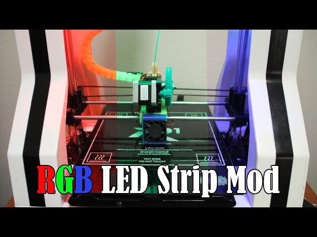
Illumination of the extruder zone on a 3D printer from profiles
The first option involves attaching an LED strip to your 3D printer's horizontal portal profile. Many 3D printers use aluminum V-groove profiles as part of the frame and gantry design, making them a great option for mounting LEDs. There are a huge number of options, it all depends on the number of tapes and your desires.
In essence, this lighting option for a 3D printer comes down to mounting an LED strip on a V-groove profile. Implementation may vary, there are many mounting options.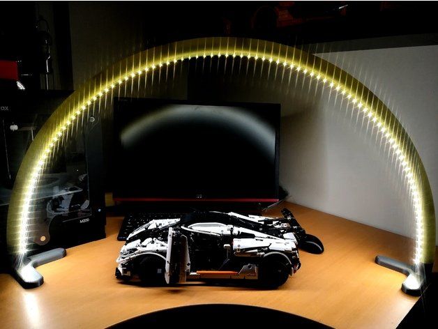 For example, you can use mounting strips printed on a 3D printer and attach the LED strip to them already. Or mount the tape directly on the profile without using additional parts.
There is an interesting way to illuminate the extrusion zone with a flashlight. The Thingiverse link below will have a fastener that you can print and mount to your frame if you are using an Ender 3 3D printer. to the body, you can do it in other ways. There are many standard fixtures for lighting fixtures, so there are many options. As a general rule, these mounts are fine if you have a closed-case 3D printer.
You can 3D print fasteners yourself. For example, here is a variant of fixtures for LED strips. You can use screws or glue for fastening. The fasteners are pretty versatile.
There are options for more specialized LED strip fixtures for a specific 3D printer. For example, here is a mount for mounting on the body of a Prusa 3D printer. For example, these 3D printable models are designed to fit on the frame of a Prusa 3D printer.
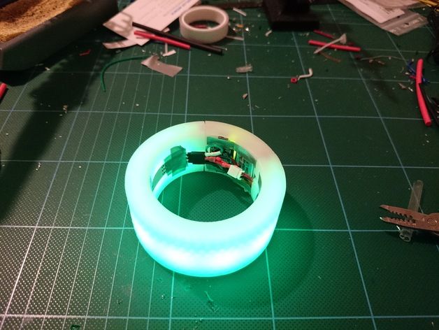
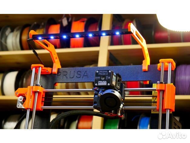
3D Printer Arch Light
Another cool option that requires a bit more effort but works great for lighting your 3D printer is the arch. After installing this arch with LEDs on your 3D printer table, you will be able to monitor both the 3D printing process and, in principle, use the large illuminated area for soldering and repairing small parts and assemblies. To make an arch, you will need a lot of 3D printed models and a rather large piece of LED strip, but the result is worth it.
3D printer light on print head
If you want to light the 3D print area directly, you can add light on the print head. This performance will help you directly illuminate the area of the current 3D print, as the source itself will move with the print head. Please note that due to the increased weight of the print head, additional noise and vibration may be generated, which may adversely affect the quality of 3D printing. As a rule, direct illumination of the 3D printing area is implemented using an LED strip, but there are other options.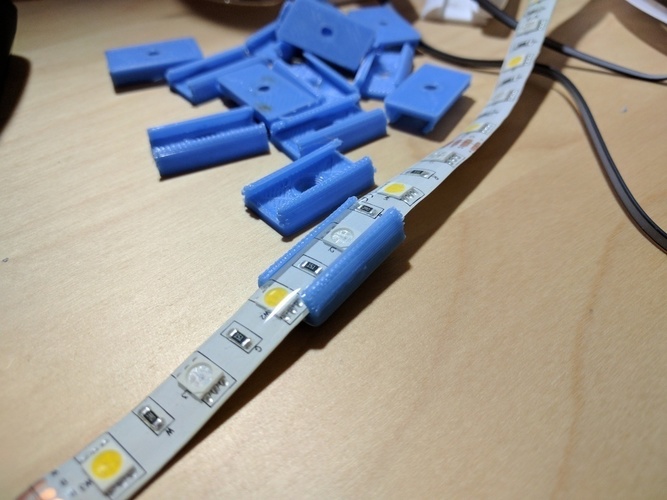 One of the easiest alternative options is to print a mount and hook up a flashlight. The choice is yours.
As options for mounts for 3D printer lighting directly on the printhead, you can consider these options that are designed for Ender 3:
- First variant of backlight mount for Ender 3
- Second variant of backlight mount for Ender 3
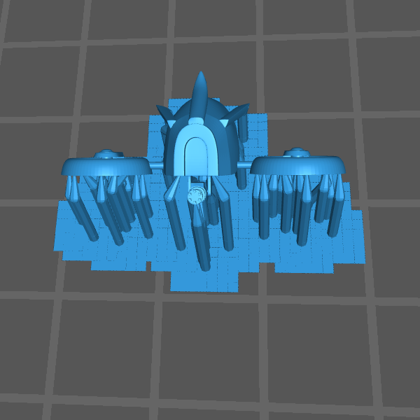
Free STL file LED strip holder・3D printer design download・Cults
Nismo Keyring
Free
Light cab Nissan 720
Free
The best files for 3D printers in the Tools category
Bottle cutter
€1.30
Single Track Spool Holder
Free
Holder for Screwdriver Set 6pcs 030 I for screws or peg board
Free
Toothpaste Squeezer
Free
Medical Mask - corona virus
Free
Main-Rotor-Head, for Helicopter, Fully Articulated Type
9,37 €
RAW COLLECTION OFFICEHÄK
3,50 €
Yellow Submarine Nexie clock IN-4 lamp
Free
Bestsellers in the Tools category
INDICATOR FOR BETTER BED LEVELING FOR ENDER 3 V2
2,90 €
UNIVERSAL BED LEVELING INDICATOR FOR VERY ALL PRINTERS
2,90 €
Business Card Embossing System
3 €
3D printed wave transmission (harmonic drive)
4. 99 €
99 €
Filament shielding
2.81 €
Cut-Man - PET bottle cutter with handle!
€3.49
PET-Machine, make your own plastic bottle filament at home!
50€ -70% 15 €
Bit holder Spartan 4 mm Hex
1,80 €
Fire hydrant container
1.94 €
well designed: Hemera fan duct
2.50 €
Ender 3, 3 V2, 3 pro, 3 max, dual 40 mm axial fan hot end duct / fang. CR-10, Micro Swiss direct drive and bowden compatible. No support required for printing
1.63 €
Ender 3 Briss fang Gen2, red lizard, spider, nf crazy, dragonfly, etc.
1.81 €
Armadillo - flexible wire conduit
€1.73 -fifty% 0.86 €
Phone holder
2.51 €
BMG E3D V6 direct drive for Creality Ender 3 (Pro/V2) & CR-10
4.49 €
BED LEVELING INDICATOR FOR ENDER 3 PRO
€2.90
Do you want to support Cults?
Do you like Cults and want to help us continue our journey on our own ? Please note that we are a small team of 3 people, so supporting us in maintaining activities and creating future developments is very easy. Here are 4 solutions available to everyone:
-
AD: Disable your AdBlock banner blocker and click on our banner ads.
Learn more