Kinect 3d scanner accuracy
Validation of a novel Kinect-based device for 3D scanning of the foot plantar surface in weight-bearing | Journal of Foot and Ankle Research
- Methodology
- Open Access
- Published:
- Giulia Rogati1,
- Alberto Leardini1,
- Maurizio Ortolani1 &
- …
- Paolo Caravaggi ORCID: orcid.org/0000-0002-8994-80621
Journal of Foot and Ankle Research volume 12, Article number: 46 (2019) Cite this article
-
4216 Accesses
-
12 Citations
-
7 Altmetric
-
Metrics details
Abstract
Background
Advancements in additive manufacturing, along with new 3D scanning tools, are increasingly fulfilling the technological need for custom devices in personalized medicine. In podiatry and in the footwear industry, custom orthotic and footwear solutions are often required to address foot pathologies or morphological alterations which cannot be managed with standard devices. While laser scanners are the current gold-standard for 3D digitization of the foot shape, their costs limit their applications and diffusion, therefore traditional operator-dependent casting methods are still in use. The aim of this study was to design and validate a novel 3D foot scanner based on the Microsoft Kinect sensor, allowing a 3D scan of the plantar shape of the foot to be acquired in weight-bearing.
Methods
The accuracy and repeatability of the prototypal foot scanner were investigated in a population of 14 asymptomatic healthy subjects, with no history of foot or lower limb injuries. The accuracy was estimated by comparing the Kinect foot scans with those obtained with a high-resolution laser scanner used as reference. The repeatability was assessed by comparing scans of the same foot acquired in different sessions.
Results
The inter-subject average Root Mean Square Error (RMSE) of the Kinect scans was lower than 3 mm for the whole plantar surface, and lower than 1.6 mm for the arch region alone, both in left and right feet. The repeatability, quantified as the average RMSE of pairwise comparisons between sessions, was 1.2 ± 0.4 mm.
Conclusions
The present Kinect-based 3D foot scanner showed optimal intra-operator repeatability and its accuracy appears adequate to obtain 3D scans of the foot plantar surface suitable for different clinical applications. This device could represent a valid low-cost alternative to expensive laser-based scanners and could be used for automatic foot measurements, supporting the design of custom insoles and footwear.
Peer Review reports
Background
There is an increasing interest in the research and development of new tools for 3D scanning and modelling of body parts to address the requirements of personalized orthotic devices and treatments [1]. In podiatry and in the footwear industry, an accurate geometrical characterization of the foot shape is critical to designing custom orthoses and footwear for different categories of people, from healthy workers [2, 3] and athletes [4], to patients with foot or lower limb issues [5], such as patients with diabetes [6, 7]. The medial longitudinal arch, the most notable morphological feature used to characterize the foot type [8, 9], allows the foot to act like a spring: when loaded vertically, it stores energy in several visco-elastic structures, such as the plantar aponeurosis, that can be recovered through elastic return [10]. The foot shape resulting from the mechanical interaction with footwear and orthoses is revealed in weight-bearing conditions, when body weight and ground reaction forces act to deform the foot joints and soft tissues spanning the medial longitudinal arch. It is widely reported that significant peak pressure reduction can be obtained with custom orthoses with respect to non weight-bearing designs [11], and to off-the-shelf insoles [12, 13].
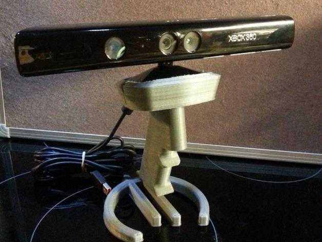 However, traditional foot casting methods can not always model the foot in weight-bearing, do not provide automatic foot measurements [14], and have been shown to be less reliable than digital scanning [15, 16]. In this respect, structured-light and laser- based scanners are currently the gold-standard for acquiring 3D high spatial-resolution images of the foot shape. In the former, a pattern of light is projected onto the foot, and cameras located at different positions detect the distortion of the pattern [17]. Laser scanners use an emitter to project a laser line on the foot and capture its reflection with one or more sensors. Both scanners use the triangulation process to reconstruct the 3D shape of the foot.
Although 3D scans are significantly cost-effective compared to the consumable costs of plaster casts [18, 19], commercial 3D foot scanners are still rather expensive (6.000–15.000€) thus strongly limiting their applications and diffusion. For this reason, the Kinect sensor, a RGB-depth camera developed by Microsoft for the videogame industry, appears to be a viable low-cost solution for 3D scanning of the foot shape. The sensor has found application as a static body scanner, e.g. in the assessment of postural control [20] and spinal deformity [21], and as a motion analysis tool [22,23,24,25,26]. While the Kinect has been used to analyse foot posture and morphology [27,28,29], a thorough validation study as a 3D foot scanner has yet to be reported.
The purpose of this study was to validate, in terms of accuracy and repeatability, a novel 3D foot scanner based on the low-cost Microsoft Kinect sensor to obtain 3D images of the foot plantar surface in weight-bearing.
Methods
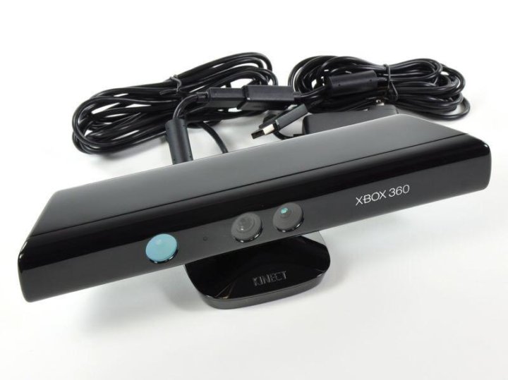
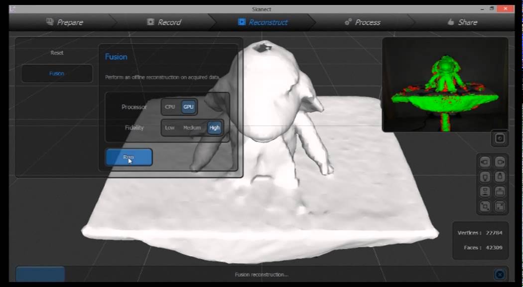
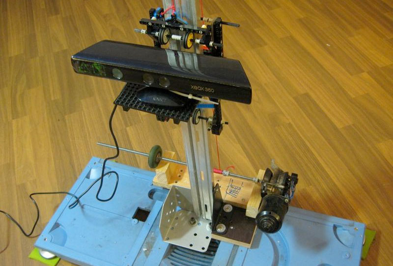
The Kinect sensor is an RGB-depth camera, developed by Microsoft (Redmond, US), which captures simultaneous depth and colour images of the surrounding environment [30]. Initially developed to enhance the gaming experience of the Xbox 360 console, the Kinect sensor has also been employed outside the gaming industry due to the release of a Software Development Kit running on MS Windows. In this investigation, a Kinect-based (Kinect for Windows, 2012 version) foot scanner was designed and tested for accuracy and repeatability.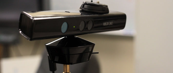 The Kinect sensor combines a laser emitter, an infrared and an RGB camera to obtain a 300.000 point-cloud 3D image of the scanned object via triangulation process [31], at a maximum of 30 fps. The scanner consists of a 0.82 m tall wood box, comprising a scanning glass plate at the top and the Kinect sensor at the bottom (Fig. 1a). The sensor is positioned above a rotating plate, manually rotated during scanning, which allows the plantar aspect of the foot to be visualized from different angles, while preserving the focus distance at 0.55 m. The scanning plate consists in a 400 × 350 × 15 mm glass plate allowing the foot plantar surface to be visualised by the depth sensor. In order to minimize light reflections, the interior walls of the wood box are painted in black and external light sources were reduced during scanning. The acquisition time was set to 25 s, to allow a slow 360 deg. rotation of the sensor. The software Skanect for Windows (Skanect by Occipital, version 1.8) was used to acquire and pre-process the raw 3D depth-data of the scanned feet (Fig.
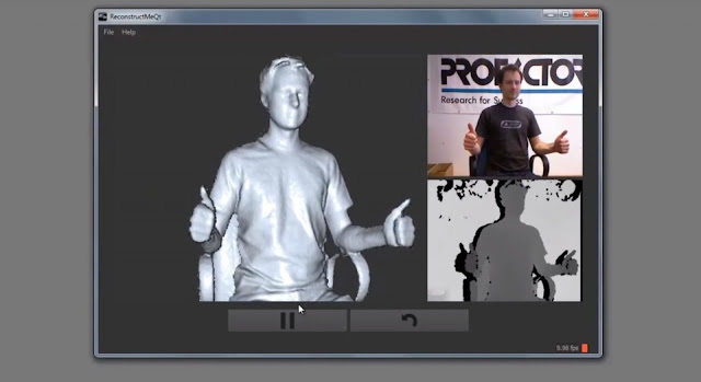 1b). The laptop computer used for data acquisition (Intel Core i5 6300 HQ @2.30 GHz, 12GHz RAM) allowed to acquire high-quality 3D images up to 21 fps.
a The Kinect-based 3D foot scanner. The Kinect sensor is located on a rotating platform at the bottom of the wood box. On top, a 15 mm thick glass plate allows to scan the foot plantar surface in different loading conditions. b 3D point cloud of the plantar foot shape of one subject in bipedal standing, visualised in Skanect
Full size image
Fourteen asymptomatic healthy volunteers (age 21–61 years; BMI 23 ± 3 kg/m2; shoe size 37–43 EU) with no history of foot and lower limb trauma or surgery were recruited for this study. According to the podoscopic evaluation the subjects were classified as having slightly flat feet (n = 5), rectus feet (n = 6) and slightly cavus feet (n = 3). A plexiglass box for foot measurements (PodoBox), featuring transparent rulers on the sides and in the bottom surface, was used to measure the foot main morphological parameters (Fig. 2). The accuracy of the device was assessed by comparing the scans of 28 feet from 14 subjects with those obtained with a high-resolution commercial 3D foot scanner (i-Qube, Delcam, UK). The scans were taken in bipedal standing - or full weight-bearing; this posture was preferred over other weight-bearing conditions for it is highly repeatable, thus helping to reduce differences in the foot shape on the two scanning devices. The 3D modelling software Geomagic Control™ (3D Systems, Rock Hill, USA) was used for spatial alignment and to calculate the average distance between the Kinect and i-Qube scans. The alignment was achieved via the “Best Fit Alignment” procedure: a preliminary gross alignment is performed by matching 5000 random points, and finer adjustments can be obtained by using 25.000 random points, until the average deviation between scans is minimized [32]. Distance Maps - i.e. the point-by-point graphical representation of the distance between the two 3D data sets - and the Root Mean Square Error (RMSE) of the distances were used to quantify the accuracy of the Kinect scans in the whole plantar surface and in the medial arch region alone.
 The latter was investigated independently because of its relevance to foot type classification and custom orthotics design.
The PodoBox: a plexiglass-made foot measuring tool. Adhesive rulers on the sides and bottom surface for arch height and arch length measurement (a), and transparent mobile rulers for foot length and foot width measurement (b)
Full size image
The repeatability of the Kinect scans across different sessions was also assessed on 28 feet of 14 subjects. The feet of each subject were scanned in three sessions a few days apart, and pairwise comparisons were performed to calculate the RMSE between scans of the same foot. Three RMSE were therefore calculated, for both right and left foot of each subject - session#1 vs. session#2, session#1 vs. session#3 and session#2 vs. session#3 - and the average RMSE for each subject’s foot was averaged across all subjects. The Coefficient of Variation of the RMSE distribution across comparisons was also used to assess the scans repeatability.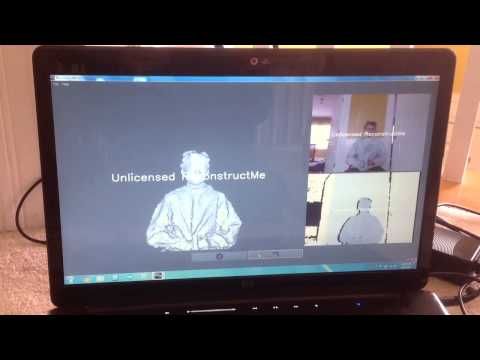
In order to assess the scanner effectiveness in detecting differences between foot types, the main morphological parameters of six sample subjects - two with flat, two with rectus and two with cavus feet - were analysed (Fig. 3). Custom software was developed in Matlab (MathWorks, R2016a) for the automatic analysis of the Kinect foot scans to estimate foot length, foot width, arch height, arch width, arch length and the Arch Index. The arch width refers to the maximum penetration of the foot arch in the medio-lateral direction, expressed as a percentage of the foot width at the same position. The Arch Index is computed as the ratio between the area of the middle third of the footprint and the total area of the footprint - toes excluded [33]. Furthermore, manual measurements of foot length and foot width, obtained using the PodoBox, were compared to the corresponding estimated by the software on the 3D scans, and the average % errors were computed.
Fig.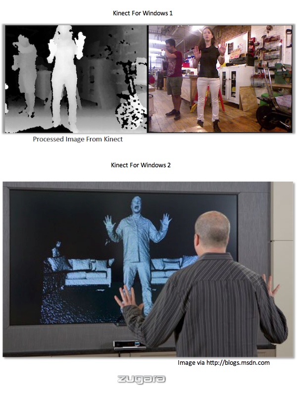 3
3Sample flat (a), rectus (b) and cavus (c) feet scanned in bipedal standing posture. Top, podoscope visualization; bottom, corresponding Kinect scans displayed in Geomagic
Full size image
Results
Kinect-scans accuracy
The accuracy in the 3D scan of the arch region was higher than that of the whole plantar surface. The comparison between 3D scans of the whole plantar surface obtained with the Kinect and with the high-resolution laser scanner (Fig. 4, top), resulted in an inter-subject average RMSE of 2.8 ± 0.6 mm and 2.9 ± 0.4 mm, respectively across left and right feet. Corresponding errors in the arch region alone (Fig. 4, bottom) were 1.4 ± 0.4 mm and 1.6 ± 0.5 mm (Table 1).
Fig. 4Color maps of the distances [mm] between laser scanner and Kinect foot scans for the right foot of one subject in weight-bearing, following the Geomagic “Best Fit Alignment” procedure. Top, error in the whole plantar region; bottom, error in the arch region alone
Full size image
Table 1 RMSE [mm] between Kinect-based and reference foot scans for each left and right foot of the 14 subjects.Full size table
Kinect-scans repeatability
Good repeatability of the Kinect scans was observed across all trials. The inter-subject average RMSE of the pairwise comparisons between scans acquired in three sessions was 1.2 ± 0.4 mm, both for left and right feet (Table 2). The inter-subject average Coefficient of Variation was 24.3 ± 12.3% and 17.4 ± 10.5%, respectively across left and right feet.
Table 2 RMSE [mm] of the distances calculated in the pairwise comparisons between the three scans of each left and right foot of the 14 subjectsFull size table
Morphological parameters of sample flat, rectus and cavus feet
The automatic analysis of the foot scans allowed estimation of the foot main morphological parameters for the 12 feet of the six sample subjects (Table 3). The main foot dimensions, foot length and foot width, were similar to the corresponding PodoBox measurements: the inter-subject average error was 1. 2 ± 1.1% and 0.9 ± 0.7%, in foot length and 9.0 ± 4.1% and 10.2 ± 3.2% in foot width, respectively across left and right feet. Arch Index and arch width values were consistent with the clinical classification; the largest Arch Index and lowest arch width were found for the four flat feet, whereas the lowest Arch Index and the largest arch width were found for the four cavus feet.
Full size table
Discussion
In podiatry, foot impression foams are still the preferred method to design semi weight-bearing custom insoles. Most of the current optical and laser-based foot scanning devices are either expensive for small clinics and non-commercial applications, or do not allow foot scanning in weight-bearing. Moreover, no automatic tool is currently available to estimate the foot’s main morphological parameters from 3D foot scans.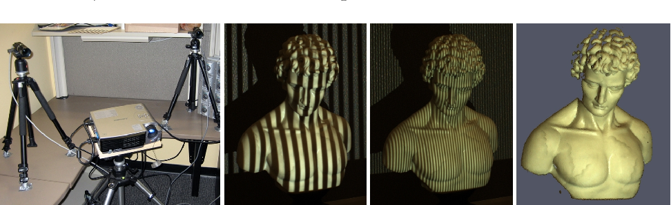 The advent of depth sensors, associated to infrared cameras and projectors, represent a cost-effective scanning tool with respect to laser-based devices. The purpose of this study was to assess the accuracy and the reliability of a novel low-cost 3D foot scanner based on the Microsoft Kinect sensor.
Preliminary tests were performed to choose the optimal scanning parameters, with the subject in bipedal standing on the scanning plate. A 360 deg. rotation of the Kinect sensor was chosen as the optimal method to guarantee the best quality of the plantar foot scans, and was preferred to a fixed position or to sensor translation.
The accuracy of the Kinect-based foot scanner was assessed on 14 subjects, using a commercial high-resolution 3D laser scanner as reference. The inter-subject average RMSE in the 3D shape of the whole plantar surface was about 3 mm, and this was very similar in the left and the right foot. The largest errors were located at the toes and in the lateral aspect of the midfoot region, approximately along the fifth metatarsal bone (see Fig. 4). It should however be highlighted that some differences in foot posture were expected especially at the toes region, as Kinect-based and reference foot scans could not be acquired simultaneously and thus may be affected by small postural differences. Therefore, the error in scanning the arch region alone, which is the foot’s most prominent morphological feature, was also investigated. The inter-subject average RMSE in the 3D shape of the medial arch was about 1.5 mm, and very consistent between left and right foot. This error, albeit rather small and consistent with the repeatability of the measurements, should be accounted for when designing personalized orthoses or in the statistical comparison of morphological data from different groups.
While the novel scanner showed very good inter-session repeatability (range 0.5 ÷ 2.2 mm), the inter-operator repeatability was not investigated in the present study. However, since the acquisition process is almost fully automatic, inter-operator errors are expected to have similar magnitude.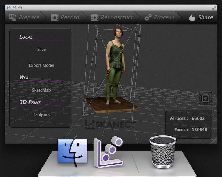
Further geometrical analysis of the plantar foot scans via custom Matlab scripts showed good agreement between the acquired 3D data sets and the clinical observations. In particular, the estimated Arch Index of the flat feet was larger than that of the cavus feet, while the arch width was the smallest in the flat feet and the largest in the cavus feet. The morphological measurements based on the Kinect foot scans appeared consistent with the real foot morphology and may represent a useful objective tool, in addition to the clinical evaluation, for foot type classification. While the average error in measuring foot length was approximately 1%, the scan-based foot width measurements were about 10% larger than the corresponding measurement from the PodoBox. This small overestimation of the real foot width may be explained by the compression of the soft tissues between the mobile ruler and the side of the PodoBox, compression that was not present during the Kinect scanning (see Fig. 2b).
From an economical perspective, the total cost of the present prototypal 3D foot scanner is about 200–300€, which is at least one order of magnitude lower than that of commercial laser-based foot scanners currently available. This should also allow clinics and research groups with limited resources to perform foot scans to support objective diagnosis of foot pathologies. Moreover, the non-invasive and automatic procedure proposed here allows foot scanning in different loading conditions, and the operator’s influence is minimal. However, the present study and its outcome should be considered in light of some limitations. While accuracy and repeatability results were largely consistent across subjects, and between left and right foot intra-subject, the sample of feet analysed is rather small. In addition, only adult feet were included, thus no information is available on the applicability and reliability of the device in scanning children’s feet. Finally, all acquisitions were performed in ideal low-light conditions with a rather powerful portable computer; lower resolution scans could be obtained and some noise may be present in real-case scenarios.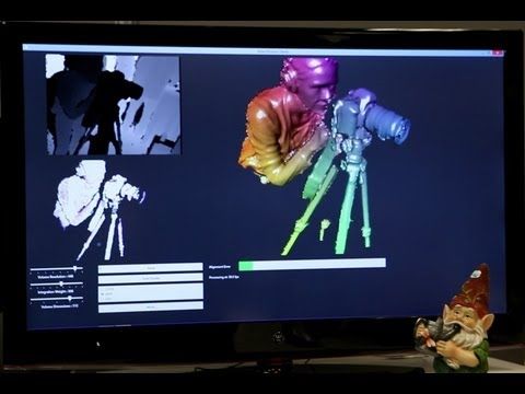
Conclusions
This study has shown that the accuracy of the Kinect sensor, within the setup specifically designed for this investigation, is comparable to that of laser-scanner devices. The sensor, therefore, may be reasonably used to obtain 3D scans of the foot plantar surface suitable for different clinical and biomechanical applications. The novel low-cost foot scanner may represent a valid alternative to more expensive laser scanners currently on the market and suitable to support the design of custom insoles and orthoses. The scans geometry can be further analysed and measured by specific software applications, as shown in the present manuscript. The combination of the Kinect-based foot scanner and of relevant analysing code presented here may represent a useful tool for automatic foot measurement, providing podiatrists and clinicians with quantitative parameters for foot type classification and diagnosis of foot morphological alterations.
Availability of data and materials
The datasets used and/or analysed during the current study are available from the corresponding author on reasonable request.
References
Chen RK, Y-a J. Wensman J, Shih a. additive manufacturing of custom orthoses and prostheses—a review. Additive Manufact. 2016;12:77–89.
CAS Article Google Scholar
Sobel E, Levitz SJ, Caselli MA, Christos PJ, Rosenblum J. The effect of customized insoles on the reduction of postwork discomfort. J Am Pod Med Assoc. 2001;91(10):515–20.
CAS Article Google Scholar
Shabat S, Gefen T, Nyska M, Folman Y, Gepstein R. The effect of insoles on the incidence and severity of low back pain among workers whose job involves long-distance walking. Euro Spine J. 2005;14(6):546–50.
CAS Article Google Scholar
Mündermann A, Nigg BM, Humble RN, Stefanyshyn DJ.
 Foot orthotics affect lower extremity kinematics and kinetics during running. Clin Biomech. 2003;18(3):254–62.
Article Google Scholar
Skou ST, Hojgaard L, Simonsen OH. Customized foot insoles have a positive effect on pain, function, and quality of life in patients with medial knee osteoarthritis. J Am Pod Med Assoc. 2013;103(1):50–5.
Article Google Scholar
Owings TM, Woerner JL, Frampton JD, Cavanagh PR, Botek G. Custom therapeutic insoles based on both foot shape and plantar pressure measurement provide enhanced pressure relief. Diab Care. 2008;31(5):839–44.
Article Google Scholar
Paton JS, Stenhouse EA, Bruce G, Zahra D, Jones RB. A comparison of customised and prefabricated insoles to reduce risk factors for neuropathic diabetic foot ulceration: a participant-blinded randomised controlled trial.
 J Foot Ankle Res. 2012;5(1):31.
Article Google Scholar
Balsdon ME, Bushey KM, Dombroski CE, LeBel M-E, Jenkyn TR. Medial longitudinal arch angle presents significant differences between foot types: a biplane fluoroscopy study. J Biomech Eng. 2016;138(10):101007.
Article Google Scholar
Saltzman CL, Nawoczenski DA, Talbot KD. Measurement of the medial longitudinal arch. Arch Phys Med Rehab. 1995;76(1):45–9.
CAS Article Google Scholar
Ker R, Bennett M, Bibby S, Kester R, Alexander RM. The spring in the arch of the human foot. Nature. 1987;325(6100):147.
CAS Article Google Scholar
Tsung BYS. Zhang M. Mak AFT: Wong MWN. Effectiveness of insoles on plantar pressure redistribution.
 J Rehabil Res Dev; 2004.
Google Scholar
Caravaggi P, Giangrande A, Lullini G, Padula G, Berti L. Leardini A. In shoe pressure measurements during different motor tasks while wearing safety shoes: The effect of custom made insoles vs prefabricated and off-the-shelf. Gait Posture. 2016;50:232–8.
Article Google Scholar
Lucas-Cuevas AG, Pérez-Soriano P, Llana-Belloch S, Macián-Romero C, Sánchez-Zuriaga D. Effect of custom-made and prefabricated insoles on plantar loading parameters during running with and without fatigue. J Sports Sci. 2014;32(18):1712–21.
Article Google Scholar
Losito J. Impression casting techniques. In: Clinical Biomechanics of the Lower Extremities. Valmassey R, editor. St Louis: CV Mosby; 1996. pp. 280–94.
Trotter LC, Pierrynowski MR. Ability of foot care professionals to cast feet using the Nonweightbearing plaster and the gait-referenced foam casting techniques. J Am Pod Med Assoc. 2008;98(1):14–8.
Article Google Scholar
Carroll M, Annabell M-E, Rome K. Reliability of capturing foot parameters using digital scanning and the neutral suspension casting technique. J Foot Ankle Res. 2011 March 04;4(1):9.
Article Google Scholar
Geng J. Structured-light 3D surface imaging: a tutorial. Adv Opt Photon. 2011;3(2):128–60.
CAS Article Google Scholar
Telfer S, Woodburn J. The use of 3D surface scanning for the measurement and assessment of the human foot. J Foot Ankle Res. 2010;3(1):19.
Article Google Scholar
Payne C. Cost benefit comparison of plaster casts and optical scans of the foot for the manufacture of foot orthoses. Aus J Am Pod Med. 2007;41:29–31.
Google Scholar
Clark RA, Pua Y-H, Fortin K, Ritchie C, Webster KE, Denehy L, et al. Validity of the Microsoft Kinect for assessment of postural control. Gait & Posture. 2012;36(3):372–7.
Article Google Scholar
Grant CA, Johnston M, Adam CJ, Little JP. Accuracy of 3D surface scanners for clinical torso and spinal deformity assessment. Med Eng Physics. 2019;63:63–71.
Article Google Scholar
Mentiplay BF, Perraton LG, Bower KJ, Pua YH, McGaw R, Heywood S, et al. Gait assessment using the Microsoft Xbox one Kinect: concurrent validity and inter-day reliability of spatiotemporal and kinematic variables.
 J Biomech. 2015;48(10):2166–70.
Article Google Scholar
Dutta T. Evaluation of the Kinect™ sensor for 3-D kinematic measurement in the workplace. Appl Ergon. 2012;43(4):645–9.
Article Google Scholar
Weiss A, Hirshberg D, Black MJ. Home 3D body scans from noisy image and range data. In: Int. Conf. on Computer Vision (ICCV). Barcelona: IEEE; 2011. pp. 1951–58.
Stone EE, Skubic M, Passive in-home measurement of stride-to-stride gait variability comparing vision and Kinect sensing. 33rd Annual International Conference of the IEEE EMBS Boston, Massachusetts USA; 2011.
Chang CY, Lange B, Zhang M, Koenig S, Requejo P, Somboon N. Towards pervasive physical rehabilitation using Microsoft Kinect, International Conference on Pervasive Computing Technologies for Healthcare (Pervasive Health), San Diego, CA, USA; 2012.
Taha Z, Aris MA, Ahmad Z, Hassan MHA, Sahim NN. A low cost 3D foot scanner for custom-made sports shoes. J Appl Mech Mat. Trans Tech Publ. 2014;440:369–72.
Article Google Scholar
Algar D, Guldberg A. Insole modeling using kinect 3d sensors. Gothenburg: Chalmers University of Technology; 2013.
Google Scholar
Mentiplay BF, Clark RA, Mullins A, Bryant AL, Bartold S, Paterson K. Reliability and validity of the Microsoft Kinect for evaluating static foot posture. J Foot Ankle Res. 2013;6(1):14 PubMed PMID: 23566934. Pubmed Central PMCID: 3639226.
Article Google Scholar
Microsoft Kinect. Available from: https://developer.microsoft.com/en-us/windows/kinect. Accessed 15 Mar 2019.
Khoshelham K, Elberink SO.
 Accuracy and resolution of kinect depth data for indoor mapping applications. Sensors. 2012;12(2):1437–54.
Article Google Scholar
Hammett PC, Garcia-Guzman LM, Geddes SW, Walsh PT. Quantifying alignment effects in 3D coordinate measurement: University of Michigan Transportation Research Institute; 2009.
Cavanagh PR, Rodgers MM. The arch index: a useful measure from footprints. J Biomech. 1987;20(5):547–51.
CAS Article Google Scholar
Download references
Acknowledgements
Not applicable
Funding
The study is partially funded by the Italian 5 × 1000 funding scheme.
Author information
Authors and Affiliations
Movement Analysis Laboratory, IRCCS Istituto Ortopedico Rizzoli, Via di Barbiano 1/10, 40136, Bologna, Italy
Giulia Rogati, Alberto Leardini, Maurizio Ortolani & Paolo Caravaggi
Authors
- Giulia Rogati
View author publications
You can also search for this author in PubMed Google Scholar
- Alberto Leardini
View author publications
You can also search for this author in PubMed Google Scholar
- Maurizio Ortolani
View author publications
You can also search for this author in PubMed Google Scholar
- Paolo Caravaggi
View author publications
You can also search for this author in PubMed Google Scholar
Contributions
GR assisted with designing the study, recruited the participants, performed the data analysis, helped with the interpretation of the results and the preparation of the manuscript.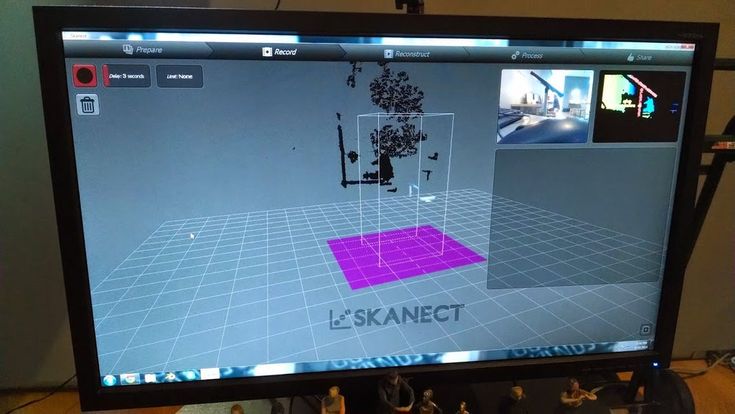 AL assisted with designing the study, helped with the interpretation of the results and the preparation of the manuscript. MO helped designing the scanning device and with the interpretation of the results. PC designed the study, designed the scanning device, assisted with data analysis, helped with the interpretation of the results and the preparation of the manuscript. All authors read and approved the final manuscript.
Corresponding author
Correspondence to Paolo Caravaggi.
Ethics declarations
Ethics approval and consent to participate
Acknowledgment of the IRCCS Istituto Ortopedico Rizzoli was granted and informed consent was obtained for all participants recruited in the study.
Consent for publication
Participants’ consent to publish was granted.
Competing interests
The authors declare that they have no competing interests.
Additional information
Publisher’s Note
Springer Nature remains neutral with regard to jurisdictional claims in published maps and institutional affiliations.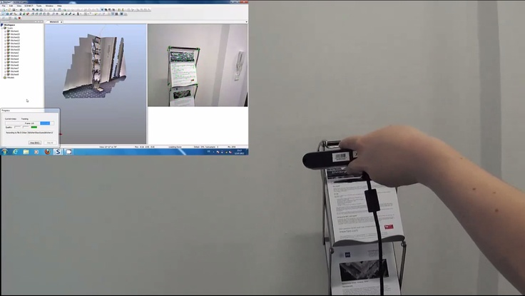
Rights and permissions
Open Access This article is distributed under the terms of the Creative Commons Attribution 4.0 International License (http://creativecommons.org/licenses/by/4.0/), which permits unrestricted use, distribution, and reproduction in any medium, provided you give appropriate credit to the original author(s) and the source, provide a link to the Creative Commons license, and indicate if changes were made. The Creative Commons Public Domain Dedication waiver (http://creativecommons.org/publicdomain/zero/1.0/) applies to the data made available in this article, unless otherwise stated.
Reprints and Permissions
About this article
Structure Sensor vs. Intel RealSense SR300 vs. Kinect V2 for 3D Scanning
This post was originally published in August 2016 and has been updated in February 2017 with more information and example scans
I just got this question as a reply to my Facebook Page:
It’s an interesting one, and the reply I wrote was so long that I decided to put it up here so it’s available for everyone with that wants to start 3D Scanning — and 3D Printing — on a budget:
Occipital Structure Sensor
Buy on Amazon ($379 including bracket)
Let’s start with the Structure Sensor (Review), because that’s the one that I have most experience with.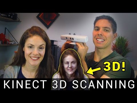 In fact, I think I scanned about
 100 200 300 objects and people with it in the last couple of months. It’s is wireless and has great standalone iPad apps and the option to scan wirelessly to a Mac or PC with Skanect (Review). That last feature means you can make scans that a tablet can’t handle, like large objects and rooms.
For 3D scanning with the Structure Sensor in general, but especially in combination with 3D printing, you should read my Review of the itSeez3D app, which adds a few handy—fully automated—features specifically for 3D printing selfies. The one-click “hollowing” procedure saves a lot of money on 3D printing.
Here are some example scans (all with itSeez3D) of a small object, medium object and human bust:
Teddy — itSeez3D 4.1 Review by Nick Lievendag | 3D Scan Expert on Sketchfab
Bust — itSeez3D 4.1 Review by Nick Lievendag | 3D Scan Expert on Sketchfab
Patrick — itSeez3D 4.1 Review by Nick Lievendag | 3D Scan Expert on Sketchfab
As you can see they’re all pretty nice. If you put the embeds in MatCap render mode you can see the geometry without textures. This might not be as detailed as a professional scanner like the Artec Eva (Review) but those cost upwards of $10,000. The textures are actually great and you can make 3D prints of these scans on small scale pretty well — especially in full color where the nice texture will compensate for the lack of geometric detail.
These scans are made with Structure Sensor, itSeez3D and 3D Printed in Full Color Sandstone by Shapeways at 10 cm height.
Intel RealSense SR300
Buy 3D Systems Sense 2 ($355.26) on Amazon
Buy Creative BlasterX Senz3D ($199) on Amazon
Buy Razer Stargazer ($149) on Amazon
There are currently three versions of Intel’s RealSense: The RealSense R200 (world-facing) sensor is a bit older, but still being sold. There used to be a F200 (user-facing) version but this has been replaced by the newer RealSense SR300, which is technically a user-facing sensor, but has enough range for 3D scanning up to human size subjects.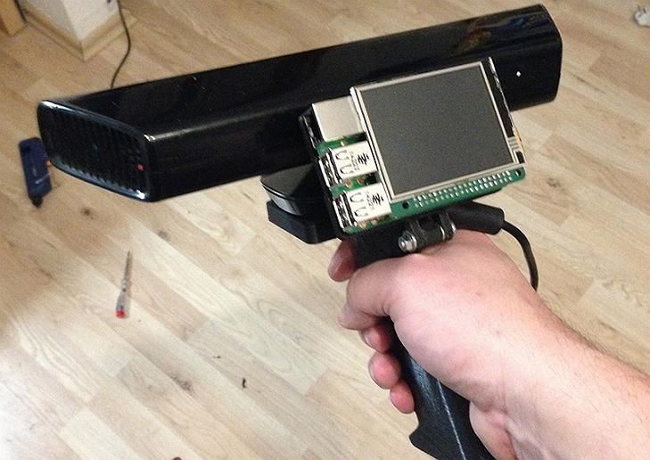
The SR300 is integrated into various devices by third parties. For 3D Scanning, the most important one is the 3D Systems Sense 2 (Review) pictured above. This version is really intended for 3D scanning and comes in a housing that makes it easy to hold it in upright position. It works with the great (and free) Sense for RealSense software.
Other products that feature the SR300 are the Razer Stargazer and Creative BlasterX Senz3D (pictured in the header image). I have a Sense 2 and the Creative device (which I purchased as a SDK from Intel earlier) and they both work with the Sense for RealSense Software. But multiple people have let me know that the Razer Stargazer doesn’t work with that Software and I’m not sure if retail versions of the Creative device will. I’ve reached out to 3D Systems to clarify this.
For those devices you can use the free Intel RealSense SDK 3D Scan app which admittedly is less good and a lot more basic than 3D System’ Sense for RealSense software.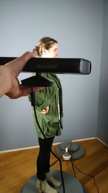
You can also use RealSense devices with RecFusion (which I will review soon) — a comprehensive software suite that costs $99. Or with Artec Studio 11 Ultimate (Reviewed as part of my Artec Eva Review) but that costs €800 a year which might be a bit steep for compared to the price of the hardware.
If you want a depth sensor to make 3D Scans on a Windows 10 machine, the RealSense SR300 is a great option. Because of the with free, versatile software I currently advice to get the 3D Systems Sense 2 instead of the slightly cheaper webcam-style alternatives.
Here are the same subjects I scanned with the Structure Sensor, scanned with the SR300:
Teddy (Medium-High) — Sense 2 Review by Nick Lievendag | 3D Scan Expert on Sketchfab
Bust (High) — Sense 2 Review by Nick Lievendag | 3D Scan Expert on Sketchfab
Patrick Bust (Low) — Sense 2 Review by Nick Lievendag | 3D Scan Expert on Sketchfab
As you can see the object scans are comparable to those made with the Structure Sensor, albeit with slightly less crispy textures. For scanning people, I found that the SR300 works okay for busts but that things get a bit tricky when trying to do full body scans (see examples of that in my Full SR300 Review). The Structure Sensor is better in that field.
Microsoft Kinect for Xbox One (a.k.a. Kinect V2)
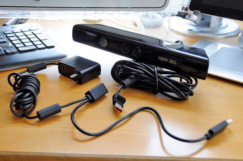
Buy Sensor on Amazon ($99.99) | Buy Windows Adapter on Amazon ($39.99)
Microsoft’s original Kinect for Xbox 360 (V1) has been responsible for the uprising of low-budget 3D Scanning. That sensor is still widely supported by many 3D Scanning apps like Skanect. This sensor is now outdated. It might still be okay for basic geometry capture, but the texture quality isn’t good enough for today’s standards.
On paper, Kinect V2 solves that by upgrading the RGB camera to HD resolution. Microsoft even used to sell a version branded as Kinect for Windows which is no longer being sold. You can still get a Kinect (V2) for Xbox One but you’ll need to buy the Windows Adapter separately.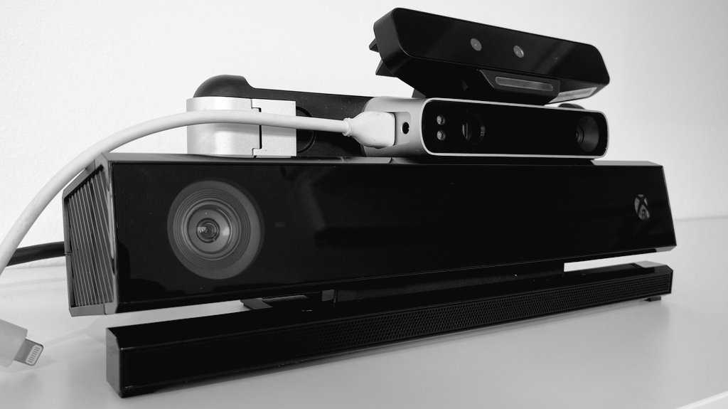 I did that because it’s still cheap and I was curious to the quality and user experience.
Sadly, both aren’t very good and can’t compare to either the Structure Sensor or the RealSense SR300. For starters, many applications that support the Kinect 360 — like Skanect, ReconstructMe and RecFusion — don’t support Microsoft’s latest depth sensor.
Microsoft does have its own 3D Scan app for Windows, but I couldn’t get anything pretty out of it. Here’s a try on the bust:
Bust — Kinect V2 with MS 3D Scan by Nick Lievendag | 3D Scan Expert on Sketchfab
The only program I could get to work with the Kinect V2 and get somewhat decent results was Artec Studio 11, but as I wrote before that costs €800 a year which is probably not the budget of people that are seeking to make 3D scans in the cheapest possible way. Here’s the result:
Bust — Kinect V2 with Artec Studio Ultimate 11 by Nick Lievendag | 3D Scan Expert on Sketchfab
That result isn’t extremely bad or anything, but as you can see the texture brightness is very inconsistent.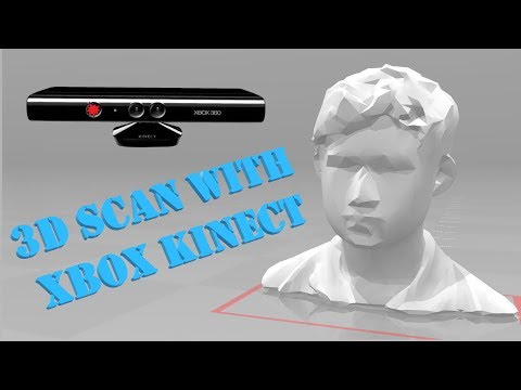 That’s because the exposure of the Kinect V2’s RGB camera cannot be locked. This means that it will adapt the brightness based on the direction you’re pointing the sensor. And because the camera’s on the Kinect V2 are very wide-angle this is a real problem.
This wide angle makes the Kinect V2 perfectly suitable for sensing motion and depth of people in front of a TV playing games, but less for 3D scanning — certainly not small things. It also makes it nearly impossible for 3D scanning on a manual turntable, because the tracking gets confused by your arm entering the frame. I scanned Teddy for comparison:
Teddy — Kinect V2 with Artec Studio 11 Ultimate by Nick Lievendag | 3D Scan Expert on Sketchfab
As a final note, it’s good to realize that the while the Structure Sensor is battery powered and the RealSense SR300 is USB-powered, the Kinect V2’s Windows Adapter needs to be plugged into a power outlet to operate. The cables are very long, but it’s still a hassle that impacts the overal user experience.
Needless to say I don’t think Kinect V2 is a contender for depth sensor 3D scanning in 2017.
This might be a good Kinect alternative!
I will soon review the $149 Orbbec Astra S which offers OpenNI2 & Android support and can be used with software like RecFusion (you can even use multiple ones simultaneously in with RecFusion Pro). The “S” version I’ll test is the Short Range version optimized for 3D Scanning people and objects. For Long Range scanning at a more Kinect-like range, take a look at the similarly prices Astra and Astra Pro (which offers HD RGB quality).
Which one should you buy? (updated)
My advice is very simple.
Don’t get a Kinect V2 for 3D Scanning. Period. Even the original Kinect 360 is more versatile if you don’t need the (texture) resolution.
If you already have a compatible iPad or the budget to buy one, you should really consider the Structure Sensor. It’s indeed “elegant 3D scanning” as Occipital calls it. It works great as a standalone device (itSeez3D is a gem!) with just the iPad and you have the extra option of streaming scan data to a PC or Mac with Skanect (again, that software review is really coming soon now!). You can scan medium to large objects by walking around them or on a turntable with ease. Scanning people is also a breeze. Just mind that you have a good light kit (I’ve written separate post about that).
If you have a decent Windows laptop (let’s say not older than 1-2 years) the Intel RealSense SR300 is also something to consider. 3D Systems has made that sensor into a great value-for-money 3D Scanner, especially because of the software. It’s great for objects, but scanning people will require some more practice. Busts are doable, but Full Body Scanning is not this sensor’s strong point.
Follow me on Twitter, Facebook or Instagram for future updates. And if you think this post could be useful for your friends and followers, please share it on your favorite social network by clicking one of the buttons below:
Subscribe to my Monthly Newsletter
Get great contents delivered straight to your inbox everyday, just a click away, Sign Up Now.
Email address
Top Ten 3D Scanners from $100 to $100,000 / Sudo Null IT News There are several ways for you: you can of course create your 3D model from scratch in a 3D modeling program or find a suitable one on the Internet, but you can also scan an existing object! The purpose of this review is to help you understand the variety of 3D scanners available and offer the best in every price segment from a photogrammetric smartphone app to professional 3D scanners.
Scanners are listed in ascending price order so you can choose the one that suits your budget and use the resulting 3D models for both 3D printing and animation.
If you are not satisfied with the proposed solutions, there is an extended overview at this link.
3D scanner in hand:
1. Best smartphone app: Autodesk 123D Catch (free)
Autodesk 123D Catch is a free photogrammetric application. It allows you to create a 3D model from photographs of an object taken from different angles. You can use it to scan objects, people, and even the landscape. For some applications, if you don't need perfect accuracy, you don't need special equipment. This application actually provides quite good detail and is easy to use. However, it will take you at least 30 minutes for the app to process your photos as the processing takes place on the server and it takes time to send them.
2. Best DIY 3D Scanner: Kinect ($99.99)
The Xbox Kinect is designed to expand your gaming experience. It is not designed for 3D scanning, but you can easily find manuals and third party software (like ReconstructMe) to turn it into a 3D scanner. If your arms are growing out of your shoulders, this is an interesting and inexpensive solution for 3D scanning.
Price: $99.99
Resolution: 0.051mm
)
This scanner can be attached to your tablet or phone (generally designed for iPad, but can be adapted to other devices). Lightweight and easy to use, with a very good resolution. Suitable for large items (can scan a full-length person) and outdoor scanning. You will be able to use it with software running on Occipital's SDK. This will increase the resolution and give you access to special features like room scanning. It probably won't be something you'll use for 3D printing, but it's interesting for game development, for example.
Price: $ 379
Resolution up to: 0.5 mm
accuracy to: 4 mm
4. The best of cheap manual 3D scanners: Cubife ($ 399)
3D 3D-scanners can be quite affordable and easy to use if you choose from inexpensive portable models. Cubify fits these criteria very well and has a relatively good resolution. But still, its capabilities are not enough for texture scanning and it is better to use it for subsequent 3D printing of one-color models.
Price: $ 399
Resolution: 0.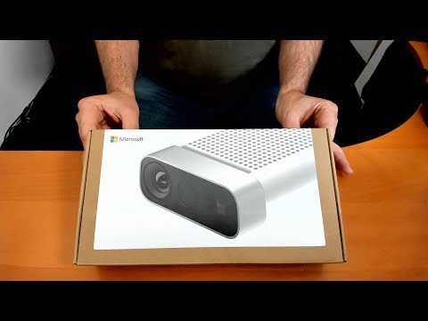 9 mm
9 mm
Resolution at a distance of 0.5 m: 1 mm
3D scanner on the table:
5. Best and cheapest table 3D 3D 3D 3D 3D 3D 3D- Scanner: Matter and Form ($519)
If you're looking to take your quality to the next level, you can purchase a desktop 3D scanner. This model is compact, easy to use, and delivers good resolution, especially considering the price (not your go-to option if you're looking for perfection, but great for educational and demo purposes). The scanning process takes place with the help of a laser and a rotating platform. The scan takes about five minutes and simultaneously reads the texture of the object.
Price: $ 519
Resolution: 0.43 mm
accuracy: ± 0.25 mm
6. The best device "two in one": XYZPRINTING DA VINCI 1.0 ($ 600)
is inexpensive combines a 3D scanner and a 3D printer. The quality of the models is not too high, but the price is very low for such a combined device.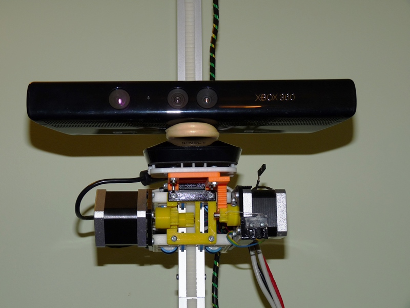 This makes the XYZprinting Da Vinci the easiest solution for beginners who want to get into the world of 3D scanning-printing.
Professional 3D scanners:
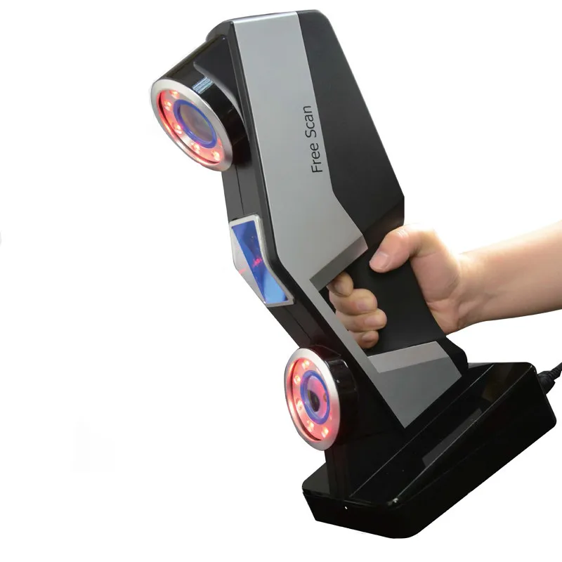
7. Best value for money portable 3D scanner: Fuel3D Scanify ($1490)
Very easy to use, intuitive, and feels good in the hand, this scanner delivers good accuracy and texture quality. The only limitation is that the size of the scanned area is limited, which is great for small objects, but for scanning a full-length person, for example, it will not work.
Price: $ 1490
Resolution: 0.35 mm
accuracy: to 0.3 mm
8. Best price The scanner uses a different scanning technology than others. Instead of a dual laser scanning system, it uses a structured light source and cameras for fast scanning with very fine detail down to 0.06mm! The scanner comes with DAVID Pro Edition 3 software that works with OBJ, STL and PLY 3D file formats that can be exported to other programs for further editing.
Price: $ 3995
Resolution: 0.06 mm
accuracy: 0.5% of the size of the object
9. The best table professional 3D-scanner: SolutionIX REXAN 4 ($ 79 900)
The 3D scanner and its price provides much better scanning quality. Solutionix Rexcan is equipped with two cameras for greater accuracy. It uses optical phase shift triangulation technology and two high-resolution CCD cameras to provide high-precision data. The scanner can be used to scan larger objects by increasing productivity with a photogrammetric system. As an option, it can be equipped with an automatically rotating platform capable of supporting up to 50 kg of weight.
Price: $ 79 900
accuracy: from 0.03 to 0.71 mm
10. Best professional manual 3D scanner: Metrascan 750 ($ 50,000 - $ 100,000)
Creaform Metrascan 750 is a complete professional, production solution for accurate 3D scanning.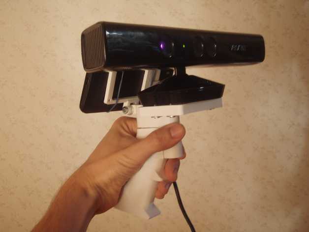 It is light, accurate, fast, and scans objects of any surface quality, with any texture with excellent accuracy.
Price: $79900
Resolution: 0.050 mm
Accuracy: Up to 0.03 mm
We hope this was a useful read and you found a 3D scanning solution suitable for your needs and your budget! If you want to learn more about photogrammetry, you can read this article.
Good luck with your 3D scanning!
The use of polarized light with Kinect increases the accuracy of 3D scanning by 1000 times
Light polarization algorithms have made it possible to create commercial depth sensors with a resolution 1000 times higher than their predecessors.
Researchers at the Massachusetts Institute of Technology (MIT) have found that the polarization of light, the physical phenomenon behind polarized sunglasses and most 3D movies, will increase the resolution of conventional 3D imaging devices by 1,000 times.
Thanks to this technology, high-quality built-in 3D cameras will appear in mobile phones and it will be possible to take photos and immediately send them to print from a 3D printer.
One of the developers of the new system, Ahuta Kadambi, a graduate student at the MIT Media Lab, said: “It is already possible today to shrink a 3D camera to the size of a mobile phone. But this affects the sensitivity of 3D sensors, which leads to a very rough reproduction of geometric shapes. We use the natural mechanisms of polarization. Thus, thanks to polarizing filters, even when using low-quality sensors, we get results that are noticeably superior in quality to images of objects from laser scanners used in mechanical engineering.”
The new system, dubbed Polarized 3D, is detailed in a paper that the developers will present at the International Computing Conference in late December. Kadambi acted as a pioneer, then joined by his academic advisor Ramesh Raskar, assistant professor of media arts and sciences at the MIT Media Lab; Boxin Shi, formerly a postdoctoral fellow in Rascar's group, is currently a Research Fellow at the Rapid-Rich Object Search Lab; and Vahe Taamazyan, a master's student at the Skolkovo Institute of Science and Technology, founded in 2011 with support from the Massachusetts Institute of Technology.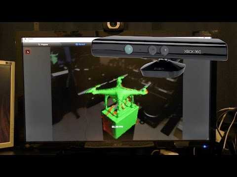
Reflection of polarized light
If we consider an electromagnetic wave as a wavy tilde, the polarization will determine the direction of the symbol. The bend can appear at the top and bottom, or on both sides of the sign, or somewhere in between.
In addition, polarization affects the specificity of light reflection from physical objects. If the light hits the object directly, most of it will be absorbed, but the entire reflected volume will have the same polarization spectrum as the incoming light beam. However, at wider reflection angles, it is more likely that the amount of reflected light within a particular range of polarizations will be greater.
That's why polarized glasses are great at eliminating glare: sunlight reflecting off asphalt or water at a slight angle tends to be a fairly concentrated polarized beam. Thus, the polarization of the reflected light conveys information about the geometry of the illuminated objects.
The existence of this relationship has been known for a long time, but it was not possible to apply the information in practice due to very ambiguous theories about polarized light. Light with a certain polarization reflected from a surface in a particular direction and transmitted through a polarizing lens cannot be distinguished from light with an opposite polarization reflected from a surface in the opposite direction.
This means that for any surface in the visual scene, for polarized light measurements, two orientation hypotheses are equally valid. The selection of all possible combinations of the position of a particular surface in order to find out which of them harmoniously fits into the geometry of the scene leads to extremely time-consuming calculations.
Polarization plus depth analysis
To end the existing uncertainty once and for all, the Media Lab researchers used rough depth calculations based on the time it takes for a light signal to reflect off an object and return to its source. Even with such additional information, determining the orientation of a surface based on light polarization measurements is quite difficult, but it can be done in real time with a graphics processor, like the specialized graphics chips of most game consoles.
The experimental set-up consisted of a Microsoft Kinect - which measures depth using reflection time analysis - and a conventional polarized photographic lens mounted in front of the camera. During each study, the developers took three pictures of the object, each time turning the polarizing filter. Based on the data obtained, the available algorithms compared the degree of illumination of the finished images.
By itself, at a distance of several meters, Kinect is able to recognize details with a diameter of about a centimeter. But thanks to polarization, the experimental system made it possible to capture elements with a size of tens of micrometers, i.e. a thousand times less.
In comparison, the researchers also imaged several objects using a high-precision laser scanner, which is designed to be pre-installed on a tablet. But even here the resolution of Polarized 3D turned out to be higher.
A mechanically rotating polarizing filter is hardly a suitable solution for a mobile phone camera, but arrays of miniature polarizing filters that can be superimposed on individual pixels in a light sensor are a great affordable alternative. Processing the equivalent of three pixels of light per image pixel will reduce the resolution of a mobile phone camera, but no more than the color filters used in modern cameras.
According to the developers' article, polarization systems will also contribute to self-driving cars. The available experimental models of such machines, in principle, can be operated under normal lighting conditions, but as soon as it starts to rain, snow or fog, the system fails. This is because water droplets in the air scatter light differently, which significantly complicates automated analysis.
In simple - though even at this level, serious computing equipment had a hard time - tests, MIT researchers were able to prove that their system can use the information of interfering light waves to eliminate errors caused by scattering. According to Kadambi: “The softening of the scattering effect in experimental scenes is only a small step forward. But I think it will soon allow a real breakthrough.