How to draw 3d printing
How to Turn a 2D Sketch into a 3D Printed Part in 3 Easy Steps
Do you have a concept sketch that you want to turn into a 3D Printed part? Read this guide to learn how to turn a simple 2D sketch, drawing, or image file into a 3D Printed part.
Learn how to turn your simple sketches into 3D Model files and 3D Printed parts.
If you can make a simple drawing, then you can make a 3D Printed part.
Getting from your sketch to a final 3D Printed part requires just one step in between: creating a 3D Model in STL file format. See this blog post to learn a little more about what 3D Model is, and why you need one in order to start 3D Printing.
This guide will walk you through how to transform your 2D sketch into a 3D Model file in STL format, and then how to use the Hollywood 3D Printing instant 3D Printing quoting tools to order your 3D Prints online.
Step 1: Make your Sketch with Dimensions
In this guide, we'll focus on turning this simple 2D outline of an anchor into a 3D Printed part. This shape outline will be copied 1-to-1 in a 3D CAD program, and then assigned a thickness to turn it into a three-dimensional model.
Your drawing should have a basic outline of your part, with any important dimensions included.
While this is a relatively basic task compared to the complex design geometry that 3D Printing is able to reproduce, it's nevertheless a foundational concept in 3D Design. Understanding how to turn a simple sketch outline into a 3D Model is the first step towards creating more detailed 3D shapes.
There are two things you want to make sure you have here: a sketch trace, and any dimensions that are important to your final part.
Sketch Trace: This is the outline of the part you'll be creating. This can be drawn free-hand; lines don't have to be perfectly straight, and you don't need to be good at drawing circles. Luckily, the design tools covered in the next step of this article will take care of this perfection for you.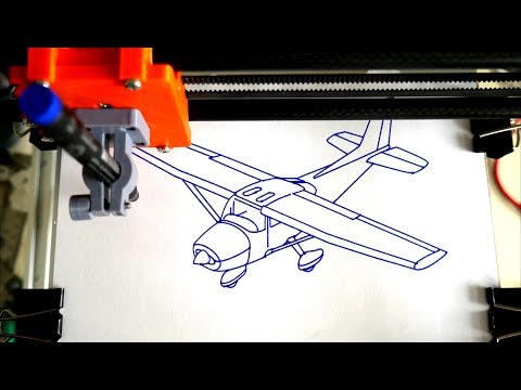
Dimensions: Define the overall size of the item you'll be creating. For a 2D shape, this can be only one dimension such as the overall height or width -- but if you have other areas where hole sizes or widths are important, you can call these out as well. For this anchor piece, we'll be focusing on only the overall height dimension to start. Then, when we're done creating our 3D Model, we can use a software measurement tool to check against the other dimensions written on the sketch.
Once you have your sketch ready, just take a picture of it -- or scan it to an image file -- and then you're ready to start creating your 3D Model design.
Step 2: Creating a 3D Model from Your Sketch
If you're new to the world of 3D Design software, creating a 3D Model from scratch may sound like a daunting task. While it's true that the 3D Design process can be a very in-depth process requiring skill and experience, you'll see here that the process of creating a 3D Model from a simple 2D sketch is quite simple.
The first thing you'll need is a 3D Design program. We recommend Autodesk Fusion 360 because it's free to start and easy for beginners, but it is also an incredibly powerful platform that will allow you to create just about anything you can imagine as you become more experienced in using the software.
While it might be more comfortable to use a more basic lighweight design tool, you'll thank yourself later for starting out with Fusion 360. Let's jump right in!
Draw a line defining your object height: When you launch Fusion 360, you'll have a new design open and ready. Press the "L" key to draw a line. This will first prompt you to select a sketch plane, so click any of the three options. We'll use the horizontal plane for a nice top-down view. Click anywhere to place your first point, and then as you go to place your second point, you'll see a text box appear. Type your height dimension into this box, and hit Enter to draw the line.
Congratulations! Now you have a line that matches the height of the anchor in the drawing.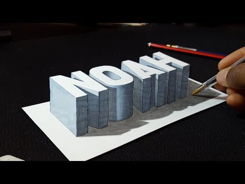 When you add your sketch image in the next step, you'll have a visual aid to help you scale the image to match this height dimension.
Import your sketch image: While still in Sketch mode, click Insert -> Canvas from the top tool menu, and select the image from your computer.
This will import your sketch into your CAD software, and then you can use the placement and sizing tools to get your image to be the same height as the height line you drew in the previous step.
When you've got your trace lined up with your height line, click OK to exit the canvas import menu. Now you're ready to trace over your sketch and create a flat profile of your shape in this 3D CAD software.
Trace the image: To trace this image, we'll use the Circle tool, Line tool, and Fit-Point Spline tool. We start off with the Circle tool, and place the center points in the middle of the round areas, and draw the circles out until they overlap with the drawing.
Use the line tool to trace over the straight areas of the drawing, and the Fit-Point Spline tool to place points along the areas of the drawing which have curvature. The Fit-Point Spline tool will create a curve which traces along the points you place one-by-one.
Since this is an object with symmetry along the vertical axis, meaning that it looks the same on the left half as it does on the right half, then we can save ourselves some time by mirroring the sketch across a vertical axis. Once you trace the left half of the drawing, you can use the Mirror tool to create that sketch geometry flipped over on the right axis.
After selecting and mirroring the left-half geometry we traced manually using the Circle, Line, and Fit-Point Spline tools, we now have a full trace of our drawing. Now it's time to create a solid three-dimensional object from this sketch geometry, using the Extrude tool.
Extrude the sketch geometry: Select the Extrude tool, and click all of the closed sketch faces that you want to give a thickness to, and type in the thickness you want them to be.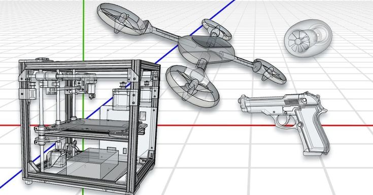 We want this part to be 10mm thick, so we type in 10mm into the Extrude tool box after selecting the sketch faces, and this gives us our final 3D Model of our anchor.
Now you have completed the process of creating a 3D Model file from your sketch. We just need to save it off in the right format for 3D Printing.
Saving as an STL file: From the Bodies section in the model tree on the left of the design area, right-click the model body, and select Save as STL. Name your file, and click Save. Now you're ready to 3D Print this STL file.
Step 3: 3D Printing Your STL File
The hardest part is over -- once you have your STL file, getting a 3D Print is simple.
When you create a user account at Hollywood 3D Printing, you get 10% off your first online 3D Printing order. You also get free access to a suite of helpful online 3D tools.
On sign-in to your Hollywood 3D Printing user account, you're directed to a blank new quote which is ready for uploading your 3D Model files in STL, OBJ, STEP, or IGES file format.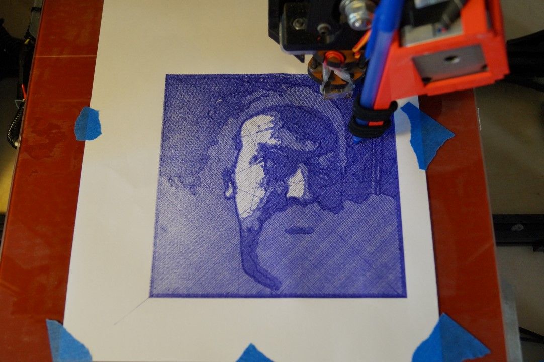 This is where we're going to be uploading the STL file created in the previous step of this guide.
When you sign in to your user account, you're directed to a blank New Quote. This is where you can upload 3D Model files and get an automatic 3D Printing quote and order parts online.
To order a 3D Print of your 3D Model file, just drag+drop your STL file over the upload icon in this window, and it will appear as a new Line Item in your automatic online 3D Printing quote.
Once your 3D Model appears as a new line item in this 3D Printing quote, you can click the "Generate Price" button. This step is where our online 3D software analyzes your 3D Model file, and determines the size of your part, how long it takes to 3D Print, and the volume of material required by the part. Based on this information, you will see a quoted price to 3D Print your 3D Model.
After adding a 3D Model file to your automatic quote, you will see a "Generate Price" button appear.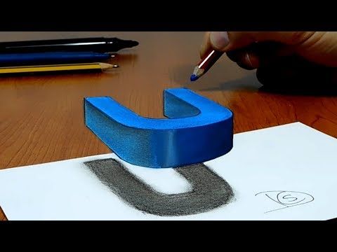 Click this button, and our online 3D software will analyze your 3D Model file and generate a 3D Printing price.
Along with this pricing information will be the dimensional size of your 3D Model. If the default choice for the 3D Model dimension units is not right, you can change your units by clicking "mm", "cm", or "in" in the Set Units section, and you will see your dimensions update.
In addition to changing the dimension units, you can select your build material option, and change the quantity of your order if you're looking for more just one part.
Upon generating a price, your 3D Printing quote will include a thumbnail image of your part, and a link to view your 3D Model in the online 3D viewer software.
From here, you are ready to proceed to checkout, and your 3D Printed part will ship to you within a matter of days.
Thanks for reading this guide! If you got this far, hopefully you now understand how to go from a simple 2D sketch to a finished 3D Printed part. We look forward to becoming your trusted 3D Printing partner.
Get Inspired
Browse through hundreds of examples of our 3D printing, 3D design, and custom fabricated builds.
What software to use for 3D printing: The complete guide
David Roberson13 May 2021
Guide
Before starting to 3D print, you will need to make sure you have gathered all the necessary software “ingredients” that will guide you through the printing process, from preparing your 3D model to managing printers themselves.
These include:
CAD software to create a 3D model (you can also use an existing 3D model, if you do not wish or need to design one)
Slicing software
Software to operate your printer remotely (this is optional, but can be convenient)
This article will go through each of these ingredients, and will also touch on how the Ultimaker platform creates a seamless end-to-end flow between hardware, software, and materials, empowering you to unlock the magic of 3D printing and make innovation happen.
What is a “slicer”?
A 3D printing slicer – also known as slicing or print preparation software – is a program that converts a 3D model into a language your 3D printer understands.
Slicing software, such as Ultimaker Cura, digitally cuts a model into flat layers, which your printer can then print one by one. With the Ultimaker platform, however, slicing software is not always needed, thanks to integrations that allow you to print directly from CAD or the Ultimaker Digital Library.
Preparing a 3D print using Ultimaker Cura software
What is the best CAD software to design 3D prints?CAD, or computer-aided design, software enables you to design a 3D model from the ground, up. There are many types of CAD software, each with its own benefits. AutoCAD, created by Autodesk, is perhaps the best-known among them since it was one of the first CAD software programs available for personal computers when released in 1982. Other CAD platforms include:
Fusion360 – great for designing and creating efficient mechanical parts
3ds Max – used in all types of 3D model creation, including video game design, architecture, and 3D printing
TinkerCAD – A free, browser-based CAD tool that allows users to build 3D models out of various shapes.
 Popular with CAD novices and for STEAM education
Blender – free, open-source 3D model creation software
Siemens NX – for designing and creating advanced 3D models
Solidworks – for designing and creating professional parts for industrial use
Catia – Advanced design software used for creating surfaces and engineering systems
Before you begin 3D printing, be sure to do your research and pick the CAD software that’s right for your use case. This way, you’ll get the most out of the model you choose to design and print.
Also check which file types your slicing software is compatible with, so you can make your 3D designs into 3D prints.
A design in CAD software (left screen), slicing software (right), and the finished print
How to design parts for 3D printing?
When designing for 3D printing, there are best practices to help you get the best results from your 3D printer and the parts it creates. Design parts optimized for 3D printing will improve print success rates, reduce costs through lower wastage, and boost the speed of your product development cycle.
Consider build volume. Your 3D prints can only be as large as your printer’s build volume. Be sure to know its dimensions, then create a part that can either be printed within those dimensions in one go, or plan to use modularity (printing then combining separate parts).
Decide orientation early. Because FFF prints layer by layer, determining the print orientation early in the process helps drive design choices, text alignment, and snap features.
Evaluate overhang support requirements. FFF printed parts are self-supporting up to 45 degrees. Overhangs below 45 degrees must be supported from below with support material.
Follow bridging support guidelines. For most basic filaments, FFF printing does not need support when bridging materials within a 10 mm gap.
Pay attention to nozzle size. When designing small features, you should consider height, wall thickness, and nozzle size. Larger nozzles will print faster than smaller nozzles, but at a cost of increased minimum thickness and height for your models.
Design with hole diameters in mind. Generally, 3D printed hole features should not be smaller than 2 mm. If accurate holes are required, it is recommended to design the holes smaller than intended and post-process with a drilling operation.
Avoid sharp corners. Sharp corners can be modelled in CAD, but the print may warp. Increasing the area of the surface in contact with the bed will decrease the likelihood of the warpage.
For a deep dive into these factors and more, check out our blog on design for 3D printing.
What software do I need to start a 3D print?
This depends on how much of the 3D printing workflow you need to perform.
As long as you already have access to a 3D model, you will typically need software that can slice that model, so your printer can get to work.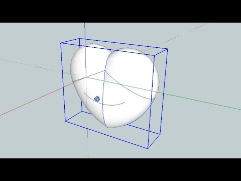 Once you have started to print, you can also use software to manager your 3D printer (or printers) remotely.
But as we saw earlier, the slicing step can be avoided if you have a 3D printer integration installed in your CAD tool. If you already have access to a 3D printable file (such as a G-code on a USB stick) you can also go ahead and print without the need for any slicing software, as your digital file is already ready to print.
Controlling 3D printers remotely with Ultimaker Digital Factory software
Managing 3D printers remotely
Ultimaker S-line printers, the Ultimaker 2+ Connect, and the Ultimaker 3 can make use of a network connection to access cloud-based services on Ultimaker Digital Factory. By linking a printer to your Ultimaker account, your printer can then be controlled remotely, from outside of its local area network.
Want to learn more about 3D printing software?
Download our free white paper, “Important 3D printing software features,” which will help you determine the best 3D printing software for your business needs, as well as examine settings, print profiles, and other features that can help you get the most out of your printing experience.
Get the white paper
Drawing on a 3D printer or Hephaestus trying on Picasso's beret
Good evening everyone!
It's no secret that the best feature of DIY printers is the incredibly wide customization and modification possibilities of the 'car'. From attaching more extruders and expanding the printable area to turning the printer into a food or musical instrument (seriously, the guys on YouTube are already moving steppers to the beat of the music). Or, for example, some make their printer draw. This is what I did today as well!
Preparing for.
In order to bring this daring plan to life, you will need:
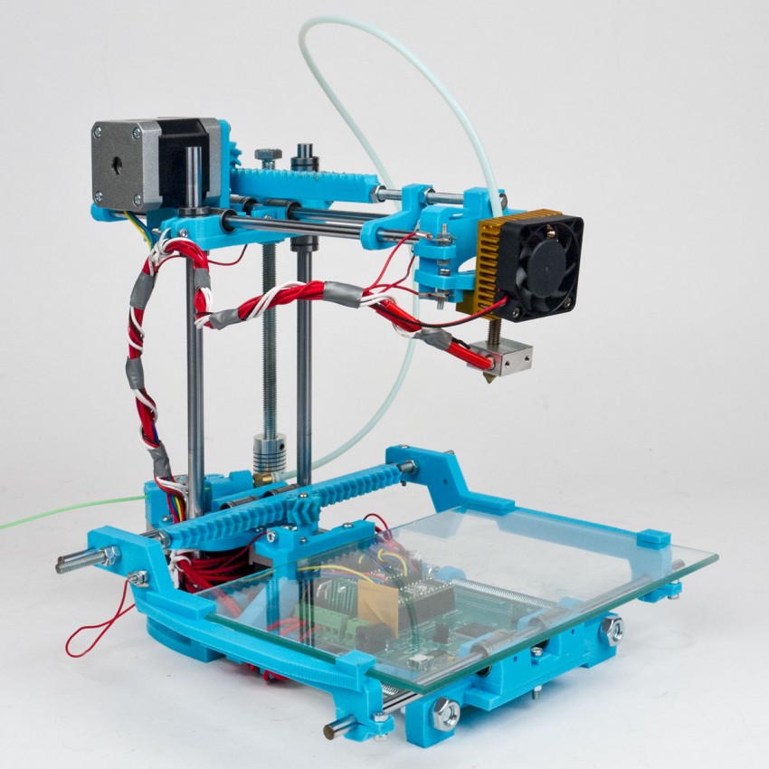
1) Printer, which plays the main role in this event. I heartily recommend the Prusa i3 Hephestos (if only for the simple reason that I have used it myself). But, in theory, any DIY or Open Source printer will do.
2) Soft. You will need the Inkscape program, which can be downloaded for free, and the gcodetools plugin for it. About what, how and where - further in the text.
3) Positive attitude on board and some free time.
Item A. An upgrade that makes your printer feel 'naked'.
For the movie magic to happen, you have to 'remove' the extruder. Those. all, including the bracket. Speaking on the example of 'Hephaestus', then in the end you should have only the printed platform-holder left from the extruder on the printer. I strongly recommend doing this carefully so as not to solder the wires to their rightful places later. After the job is done (I have no doubt about you, in the end you somehow assembled this DIY into its current state), you need to install a pen holder on the platform.
You can download them from the well-known site. Here are the holder links for
- RepRap: www.thingiverse.com/thing:31983
- Hephestos: http://www.thingiverse.com/thing:627774/
Personally, I printed the holder with 15% infill and thickness layer 0. 3 - no problems experienced. The holder itself can be mounted on the same bolts that were used to mount the extruder. The result is such a nice design:
A few words about the calibration and the level at which you install this same pen. Personally, I did it extremely simply - through the level plate I brought it to the point when the printer brings the extruder to the center of the platform and set the handle so that there is a sure contact between the tip of the rod and the paper previously installed on the platform. The method, of course, only works if the platform is pre-calibrated. But tough guys don't look at the explosion and don't calibrate the table, so that shouldn't be a problem.
Item B. Preparing to transfer beauties and not-so-beauties onto paper.
As mentioned above, you need to download Inkscape. You can download it from the official site at this link. And here you can download gcodetools. The contents of the archive must be unpacked to *Inkscape installation location*shareextensions. Create a separate folder for the plugin DO NOT NEED . When all these boring items are completed, feel free to run the program.
[IMG ID=3063 WIDTH=514 HEIGHT=289]
Initially, I really wanted to draw a patriotic pin-up beauty, but life makes its own adjustments. It should be noted that in general gcodetools was created for extremely serious CNC guys, and therefore I have been digging into it all day, but some functions are still not given to the Padawan. If not today, then tomorrow all pin-up beauties will be drawn, but for now we have to curb our appetite - let's circle this drawing!
With a habitual movement, we throw this guy in .jpg directly from the desktop into the program workspace. Immediately, by the way, in file-> document properties I recommend setting the size of the drawing area. I set it to 180 x 180mm, well within the hephestos print area.
Now let's bring the drawing into a state that our printer can handle. Let me remind you that he can only operate with a pen - that leaves us with only the shaded and unpainted areas. Go to Path->Trace Bitmap.
The main setting we are interested in is Brightness cutoff. This setting is worth fiddling with. The value that suits me is 0.450. It doesn't have to be the same for you. Before clicking 'ok', make sure you have the image selected that you want to convert like this. Also note that the result will appear ON TOP of the original.
Now go to extensions-> gcodetools-> Path to Gcode.
Here we change, first of all, the cutting order to Pass by Pass. Thus, the handle will not make unnecessary gestures. I'm not entirely sure I understand her, but the guys in the know say, 'Believe me. and then you'll understand. Then go to the preferences tab. Everything is simple here - the file name, the path where it will be saved, and z safe (as you might guess, this is the distance that the pen will rise when it needs to move - the standard 5 mm is enough).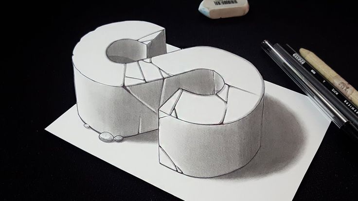
VERY IMPORTANT: be sure to add .gcode to the end of the file name. Otherwise, there will be no kin.
After playing around with these options, return to the path to Gcode tab. With a feeling of maximum dignity, press Apply. Warnings will pop up that you haven't set orientation points and tool, so the whole thing will be set to 'default'. We are satisfied with this option, click 'OK'.
Finally, your file is ready. We fill it on a USB flash drive and send it to the printer for 'drawing'.
The process, it must be said, is fascinating. For those who are 'long' - I turned the speed up to 300%. Things went extremely well without any collateral damage. The printer finished drawing in about half an hour:
Personally, I am completely satisfied with the result. For those who were waiting for a pin-up beauty, not this tin can - as you can see, by creating a file in this way, we get a 'stroke'.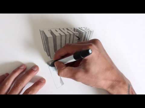 Accordingly, the printer does not paint over areas filled with black. This can be easily solved if you dig deeper into the plugin settings and Area in particular. If necessary, I will show and tell you more in a separate post or comment.
Thank you all for your attention, stay with us. Drawing printers, big guys in bat suits and educational projects are guaranteed. Further more!
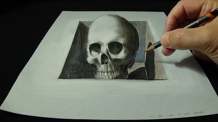
Printing 3D objects in Photoshop
User's Guide Cancel
Search
Last update Dec 13, 2021 08:23:10 PM GMT
- Photoshop User Guide
- Introduction to Photoshop
- Dream about it. Do it.
- What's New in Photoshop
- Editing the first photo
- Create documents
- Photoshop | Frequently Asked Questions
- Photoshop system requirements
- Transfer of presets, operations and settings
- Introduction to Photoshop
- Photoshop and other Adobe products and services
- Working with Illustrator artwork in Photoshop
- Working with Photoshop files in InDesign
- Substance 3D Materials for Photoshop
- Photoshop and Adobe Stock
- Working with the built-in Capture extension in Photoshop
- Creative Cloud Libraries
- Creative Cloud Libraries in Photoshop
- Working in Photoshop using the Touch Bar
- Net and guides
- Create transactions
- Cancellation and transaction history
- Photoshop on iPad
- Photoshop on iPad | General questions
- Introduction to the working environment
- System requirements | Photoshop on iPad
- Creating, opening and exporting documents
- Adding photos
- Working with layers
- Drawing and painting with brushes
- Selecting areas and adding masks
- Retouch compositions
- Working with Adjustment Layers
- Adjusting the key of a composition using the Curves layer
- Applying transform operations
- Trim and rotate compositions
- Rotate, pan, zoom and restore canvas
- Working with text layers
- Working with Photoshop and Lightroom
- Getting missing fonts in Photoshop on iPad
- Japanese text in Photoshop on iPad
- Application parameter management
- Touch shortcuts and gestures
- Key combinations
- Image resizing
- Live stream your creative process in Photoshop on iPad
- Correct imperfections with the Healing Brush
- Creating brushes in Capture and using them in Photoshop
- Working with Camera Raw files
- Creating and using smart objects
- Adjusting the exposure of images with the Dodge and Burn tools
- Photoshop Web Application Beta
- Frequently Asked Questions | Photoshop Web App Beta
- Working environment overview
- System requirements | Photoshop Web Application Beta
- Keyboard shortcuts | Photoshop Web Application Beta
- Supported file formats | Photoshop Web Application Beta
- Opening and working with cloud documents
- Collaboration with stakeholders
- Limited cloud document editing capabilities
- Cloud Documents
- Cloud Documents Photoshop | FAQ
- Photoshop Cloud Documents | Workflow Questions
- Work with and manage cloud documents in Photoshop
- Cloud storage update for Photoshop
- Unable to create or save cloud document
- Troubleshooting Photoshop cloud documents
- Collection of cloud document sync logs
- Sharing and editing cloud documents
- File Sharing and Commenting in Application
- Working environment
- Working environment basics
- Learn faster with the What's New panel in Photoshop
- Create documents
- Working in Photoshop using the Touch Bar
- Tool gallery
- Performance settings
- Using tools
- Touch gestures
- Touch gestures and customizable workspaces
- Overview versions of technology
- Metadata and comments
- Default key combinations
- Touch gestures and custom workspaces
- Putting Photoshop images in other applications
- Installations
- Default key combinations
- Rulers
- Show or hide non-printing auxiliaries
- Specifying columns for the image
- Cancellation and transaction history
- Panels and menus
- File location
- Positioning of elements with referencing
- Positioning with the ruler tool
- Setting sets
- Customizing keyboard shortcuts
- Net and guides
- Web, screen, and application content development
- Photoshop for design
- Artboards
- View on device
- Copy CSS from layers
- Dividing web pages into fragments
- HTML options for snippets
- Changing the arrangement of fragments
- Working with web graphics
- Create web photo galleries
- Understanding images and color
- Resizing images
- Working with raster and vector images
- Image size and resolution
- Importing images from cameras and scanners
- Creating, opening and importing images
- Image viewer
- "Invalid JPEG marker" error | Opening images
- Viewing multiple images
- Customize color palettes and color swatches
- HDR images
- Image color matching
- Converting between color modes
- Color modes
- Erase image fragments
- Blend Modes
- Color selection
- Making changes to indexed color tables
- Image information
- Distortion filters not available
- Color details
- Color and monochrome corrections with channels
- Selecting colors in the Color and Swatches panels
- Sample
- Color mode (or image mode)
- Shade
- Adding a color mode change to an operation
- Add swatches from CSS and SVG files HTML
- Bit depth and settings
- Layers
- Understanding Layers
- Reversible editing
- Create and manage layers and groups
- Selecting, grouping and linking layers
- Putting images into frames
- Opacity and layering
- Layer masks
- Application of smart filters
- Layer compositions
- Move, arrange and lock layers
- Masking layers with vector masks
- Manage layers and groups
- Effects and Layer Styles
- Editing layer masks
- Extract resources
- Display layers with clipping masks
- Generation of graphic resources from layers
- Working with Smart Objects
- Blend Modes
- Combining several fragments into one image
- Combining images with Auto Layer
- Alignment and distribution of layers
- Copy CSS from layers
- Load selections based on layer boundaries or layer masks
- See-through to show the contents of other layers
- Layer
- Mixing
- Composite images
- Background
- Selections
- Select and Mask workspace
- Quick area selection
- Getting Started with Selections
- Selecting with the Marquee toolbox
- Selecting with the Lasso tools
- Selecting a color range in an image
- Pixel highlight setting
- Convert between contours and selection boundaries
- Channel Basics
- Moving, copying and deleting selected pixels
- Creating a temporary quick mask
- Saving selections and alpha channel masks
- Selecting focus areas in an image
- Duplication, splitting and merging of channels
- Channel calculation
- Extraction
- Bounding box
- Image corrections
- Perspective distortion
- Reducing blur due to camera movement
- Healing Brush Tool Examples
- Export color lookup tables
- Image sharpness and blur correction
- Understanding color grading
- Applying the Brightness/Contrast setting
- Shadow and Highlight Detail Correction
- "Levels" correction
- Hue and saturation correction
- Juiciness correction
- Adjusting the color saturation in image areas
- Quick tone correction
- Applying special color effects to images
- Image enhancement with color balance correction
- HDR images
- View histograms and pixel values
- Image color matching
- Crop and straighten photographs
- Converting a color image to black and white
- Adjustment and fill layers
- Curves correction
- Blend Modes
- Press 9 Target Imaging0080
- Color and tone correction with Levels and Curves eyedroppers
- HDR Exposure and Toning Compensation
- Filter
- Blur
- Lighten or darken image areas
- Selective color correction
- Replacing object colors
- Adobe Camera Raw
- Camera Raw system requirements
- What's New in Camera Raw
- Introduction to Camera Raw
- Creating panoramas
- Supported lenses
- Camera Raw Vignetting, Grain, and Haze Removal
- Default key combinations
- Automatic perspective correction in Camera Raw
- Reversible editing in Camera Raw
- Camera Raw Radial Filter Tool
- Manage Camera Raw settings
- Processing, saving and opening images in Camera Raw
- Image enhancements with Camera Raw 9's improved Spot Remover0080
- Rotating, cropping and modifying images
- Camera Raw color correction
- Function overview | Adobe Camera Raw | Issues for 2018
- Overview of new features
- Processing versions in Camera Raw
- Making local adjustments in Camera Raw
- Fixing and restoring images
- Removing objects from photos using Content-Aware Fill
- Patch and move content-aware
- Retouching and fixing photos
- Image Distortion and Noise Correction
- Basic troubleshooting steps to solve most problems
- Image transformation
- Object transformation
- Crop, rotate and canvas settings
- Crop and straighten photographs
- Creating and editing panoramic images
- Deforming images, shapes and contours
- Perspective
- Using the Plastic filter
- Content-aware scale
- Transforming images, shapes and paths
- Deformation
- Transformation
- Panorama
- Drawing and painting
- Drawing symmetrical ornaments
- Options for drawing a rectangle and changing the stroke
- Drawing details
- Drawing and editing shapes
- Paint tools
- Creating and modifying brushes
- Blend Modes
- Adding color to outlines
- Edit contours
- Painting with mix brush
- Brush Presets
- Gradients
- Gradient interpolation
- Fill and stroke selections, layers, and paths
- Draw with the Pen tool group
- Creating patterns
- Creating a pattern with the Pattern Builder filter
- Circuit control
- Managing pattern libraries and presets
- Drawing with pen tablet
- Creating textured brushes
- Adding dynamic elements to brushes
- Gradient
- Draw stylized strokes with the Archive Art Brush
- Drawing with pattern
- Synchronizing presets across multiple devices
- Text
- Adding and editing text
- Universal text editor
- Working with OpenType SVG fonts
- Character formatting
- Paragraph formatting
- Creating text effects
- Text editing
- Leading and letter spacing
- Font for Arabic and Hebrew
- Fonts
- Troubleshooting fonts
- Asian text
- Creating text
- Text Engine error when using the Type tool in Photoshop | Windows 8
- Adding and editing text
- Video and animation
- Video editing in Photoshop
- Editing video and animation layers
- Introduction to video and animation
- Video and animation preview
- Draw frames in video layers
- Import video files and image sequences
- Creating frame animations
- Creative Cloud 3D Animation Preview
- Creating timeline animations
- Creating images for videos
- Filters and effects
- Using the Liquify filter
- Using Blur Gallery group effects
- Filter basics
- Filter effects reference
- Adding lighting effects
- Using the Adaptive Wide Angle filter
- Oil Paint Filter
- Effects and Layer Styles
- Application of specific filters
- Image area feathering
- Saving and exporting
- Saving files in Photoshop
- Export files to Photoshop
- Supported file formats
- Saving files in other graphic formats
- Moving projects between Photoshop and Illustrator
- Saving and exporting video and animation
- Saving PDF files
- Digimarc copyright protection
- Saving files in Photoshop
- Printing
- Printing 3D objects
- Printing with Photoshop
- Printing and color management
- Checklists and PDF presentations
- Print photos in a new image layout
- Spot color printing
- Duplexes
- Printing images on a printing press
- Photoshop Color Enhancement
- Printing troubleshooting | Photoshop
- Automation
- Create activities
- Creation of data-driven images
- Scenarios
- File batch processing
- Operation playback and management
- Adding conditional operations
- About actions and the Actions panel
- Recording tools in operations
- Adding a color mode change to an operation
- Photoshop UI Development Kit for plug-ins and scripts
- Color Management
- Understanding Color Management
- Accurate color assurance
- Color settings
- Working with color profiles
- Color management of documents for viewing on the web
- Color management for printing documents
- Color management of imported images
- Perform proofing
- Content Authenticity
- Learn more about content credentials
- Identity and origin of NFT tokens
- Connecting accounts for creative attribution
- 3D objects and technical images
- 3D in Photoshop | Common questions about deprecated 3D features
- Creative Cloud 3D Animation Preview
- Printing 3D objects
- 3D drawing
- 3D Panel Enhancement | Photoshop
- 3D Concepts and Tools
- Rendering and saving 3D objects
- Creating 3D objects and animations
- Image stacks
- 3D graphics workflow
- Measurements
- DICOM files
- Photoshop and MATLAB
- Counting objects in an image
- Merging and transforming 3D objects
- Editing 3D textures
- HDR Exposure and Toning Compensation
- 3D panel settings
Photoshop allows you to print any compatible 3D model without worrying about the limitations of a 3D printer. When preparing to print, Photoshop automatically renders 3D models impenetrable. Photoshop also generates the necessary support structures—platforms and bases—to help you achieve successful 3D printing results.
- Select the menu item Window > Workspace > 3D to switch to 3D mode.
- Open the 3D model in Photoshop. If necessary, resize the 3D model while opening the file.
- Select menu item 3D > 3D Print Settings.
- In the 3D Printing Preferences panel, choose whether to use a printer connected to your computer via USB (local printer) or online 3D printing services such as Shapeways.com or Sculpteo.
You can now print 3D models as 3MF (3D Manufacturing Format) files. When specifying 3D printing options, set Print to to Local and set Printer to 3MF file. When you send a 3D object to print, Photoshop creates a 3MF file. On Windows computers, Photoshop also launches the Microsoft 3D Builder application to further process the 3MF file.
To update the list of supported printers or online profiles, select Get Latest Printers from the Send to Print To pop-up menu.
- Select a local printer or Shapeways.com print profile.
View estimated prices for printing 3D models using available Shapeways.com profiles by selecting Printer > Estimated Price.
- Select the unit of measure for print volume from inches, centimeters, millimeters, or pixels. This unit will serve to measure the dimensions of the volume of the printer as well as the dimensions of the printing plate.
A. 3D model B. Printing plate C. Printer volume overlay
- Select the 3D Printing Detail Level - Low, Medium, or Fine. The time it takes to print a 3D object depends on the level of detail selected.
- If you don't want to see the bounds of the 3D print volume, clear the Show Printer Volume Overlay check box.
- Set the Scene Volume options to the appropriate size for the 3D printed object. When you change one value (X, Y, or Z), the other two values are scaled proportionally. When resizing the Stage Volume, notice that the print plate under the 3D model resizes accordingly.
You can scroll through the Scene Volume settings by clicking the size label (X, Y, or Z) and dragging the cursor left or right. By holding down the Shift key, you can scroll through the values faster.
- Select Scale by printer volume if you want to automatically resize the 3D model so that it takes up the entire available printer volume on the selected printer.
- If your 3D model includes normal maps, bump maps, or transparency maps, you can ignore these types of maps when printing the model. Notice how the 3D model changes in real time as you change the Surface Detail settings.
- Optionally, you can exclude the support structures of the 3D object (platforms and bases) from printing.
 Use this option with caution as printing a 3D model without the necessary support structures may produce unsatisfactory results.
 - If your printer supports multiple materials, select the material you want to use to print this 3D object.
You can enable an experimental feature that allows you to print continuous tones with your MakerBot Replicator 2x 3D printer.
Requirement: Enable experimental Photoshop features
Experimental features must be enabled in Photoshop before using multitone printing:
- Select Preferences > Experimental Features.
- Select the Enable multitone printing check box.
- Click OK.
- Restart Photoshop.
Experimental features not yet fully tested. They should be used with caution.
Choose a multi-tone surface material
- Select the MakerBot Replicator 2x printer in the 3D Printing Settings panel.
- In the Material field, select Multitone Surface.
 If you don't see this option, make sure the experimental Multitone 3D Printing feature is enabled.
- Set other parameters according to the generated 3D model.
- To view and print a 3D object, select 3D > 3D Print.
After setting the 3D printing options, follow these steps.
- Click the Start Print icon () or select the menu item 3D > 3D Print. Photoshop will combine the 3D elements of the scene and prepare it for the printing process.
- If you choose to print with a Shapeways.com profile, Photoshop will display a message that the actual print cost may differ from the estimated cost displayed. Click OK.
- In the preview window that opens, you can use the 3D camera tools to rotate, scale, or move the 3D object.
Rotate the 3D camera.
3D camera rotation.
Move the 3D camera.
3D camera slide.
Return to the home position of the 3D camera.
- If necessary, select the Show restoration check box.
 Photoshop displays various restoration colors such as Initial Mesh, Thickened Walls, and Hole Closed.
- You can also turn on Ray Tracing Preview. Viewing ray tracing allows you to more accurately reproduce the printed material.
- If you want to export the 3D printing settings to an STL file, click the Export button and save the file to the desired folder on your computer. This STL file can be sent to a network service server or moved to an SD card for printing with your own printer.
- View a summary of the 3D print object and click the Print button.
You can cancel the current 3D printing process using the menu item 3D > Cancel 3D Printing.
Photoshop provides interactive step-by-step utilities that you can use to set up, calibrate, and maintain your 3D printer. These utilities can only be used when the 3D printer is turned on and connected to a computer.
- Select the menu item 3D > 3D Printer Utilities.
- Select the utilities you want to run.
Print plate calibration
Helps in leveling the printing plate. This utility includes the following general steps:
- Requires you to remove all residual print materials from the 3D printer.
- Initializes the printhead.
- Allows you to adjust the amount of gap between the platen and the printhead at nine nozzle positions.
You can use this utility in wizard mode or manual mode.
Download Thread
Helps load filament into a Fused Deposition Modeling (FDM) 3D printer. To facilitate filament loading, Photoshop starts the head heating process and the filament loading mechanism.
Remove thread
Helps remove the filament from the FDM 3D printer. To facilitate the removal of the filament, Photoshop starts the head heating process and the filament loading mechanism.
Replace thread
Helps to replace the old filament in the FDM 3D printer with a new one. To make changing filament easier, Photoshop starts the head heating process and the filament loading mechanism.
- Follow the instructions on the screen.
Sometimes you may want to print multiple instances of an object on the same panel. Do the following.
- Select the required objects in the 3D panel.
- Select 3D > Pack Objects on Ground Plane.
- Start printing objects.
Photoshop currently supports the following 3D printers:
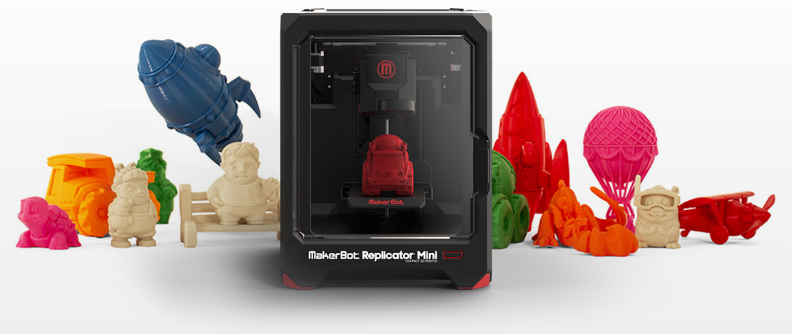
- MakerBot Replicator 2
- MakerBot Replicator 2x
- ZCorp Full Color
- Mcor Iris
- MakerBot Replicator 5th Generation
Photoshop also supports several Shapeways. com and Sculpteo profiles.
MakerBot Replicator 5th Generation Printer Profile does not yet support USB direct printing. You can export files to a USB drive and print them to a local printer.
Yes. Before printing, you can set a cross section to cut off part of the 3D model. Follow these general steps.
- Select the menu item Window > Workspace > 3D to switch to 3D mode.
- Open the 3D object you want to print.
- Select Scene in the 3D panel.
- On the Properties panel, select Cross Section.
- Specify the cross section parameters in the Properties panel.
- Select the menu item 3D > Apply Cross Section to Scene.
- Print the 3D scene.
The desired cross section must be dried before printing.
Yes. Follow these general steps.
- Select a material in the Scene panel.
- In the Properties panel, click the folder icon () next to Emboss/Transparency/Normals and load the texture.
Learn more