How to 3d print stl file
Complete Guide to 3D Printing STL Files
RECENT STORIES
TPR vs. PVC: Material Differences and Comparisons
December 23, 2022
6 min read
TPR vs. Latex: Material Differences and Comparisons
December 23, 2022
8 min read
Alloy Steel vs. Stainless Steel
December 23, 2022
8 min read
3D printers produce three-dimensional parts via additive manufacturing methods. This technology adds material in layers to produce a 3D object. Most 3D printing software reads a file format known as STL (Standard Tessellation Language or Standard Triangle Language). The STL file format was originally native to 3D Systems’ stereolithography CAD (Computer Aided Design) software, but it has become a 3D printing industry standard. STL prescribes the outer shape of the model object. Before printing a 3D print model, the image must be transformed from the STL format to G-code (referred to as the printing machine code).
This article provides a complete guide to 3D printing STL files, including the process, description, and the format’s pros and cons.
1. Recognize the STL Resolution.
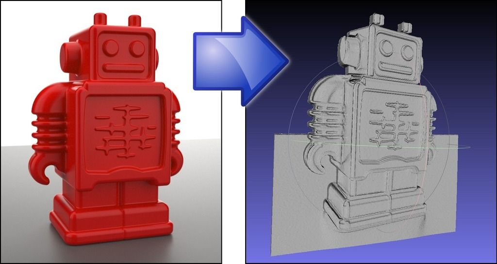
To print a part with the proper specifications, the STL file must be built at an appropriate resolution. STL files define the 3D model’s outer shape by subdividing the surface into interconnected triangles. At higher resolution, the CAD program breaks the model down into smaller triangles so it can more closely approximate the desired shape. Reducing resolution, likewise, creates a less accurate approximation and is thus less desirable. However, there is a balance. As the digital resolution increases, the file size grows dramatically. Large files overtax both the design and printing computer. And since every 3D printer has a physical resolution limit, there is no benefit to exceeding that resolution in the digital STL model.
2. Select the Appropriate Exporting Settings.
The export settings can impact the quality, dimensional accuracy, and surface finish of the 3D printed part. Those settings must be selected in the CAD software before converting the model to STL format. Most programs require you to specify two key settings when you export: the chordal tolerance/deviation and the angular tolerance/deviation.
The chordal tolerance/deviation defines the maximum allowable divergence (in microns) between the as-designed CAD surface and the surface of an STL triangle face. Most experts recommend a chord deviation of about 1/20th of the printer’s layer thickness, but not less than 1 micron.
The angular tolerance/deviation, on the other hand, defines how far the exported model can deviate from any given angle in the CAD model. The standard recommended setting is 15°. Some programs define angular tolerance as a value between 0 and 1 with 0 equating to 15°. Angular tolerance is important in small angular features that might get cut off because they’re smaller than the chord tolerance.
3. Export STL Files From Your CAD Software.
Nearly all CAD programs can export files in STL format, but each one does it a little differently. Most often, the export option will be found under ‘File’ and ‘Save as,’ but it’s best to consult your specific software’s documentation if you’re unsure. The export menu is often where you specify chord and angular tolerances as well as properties like poly count. You may also have the option of saving in binary or ASCII format.
What Is an STL File?
An STL file is the digital file format that 3D printers and slicing programs can read. It defines the surface geometry of the object in a simplified, purely geometrical manner, ignoring aesthetics.
What Is the Purpose of STL Files?
STL files deliver a description of the 3D model’s outer shape. Aesthetic details such as color, texture, and material are not included in the file contents. The STL export process converts the overall model into a more basic, faceted model composed of triangular polygons. That model can then, in turn, be interpreted by slicing software or by the 3D printer itself.
Why Are STL Files Used by 3D Printers?
3D printers use the simplified STL file format because it is easier to convert into 2D “slices” that can be laid down successively. Though many CAD programs build in their own file formats, STL is compatible with nearly all of them.
What Are the Pros and Cons of STL Files?
The pros and cons of STL files are shown in table 1 below:
Table 1: STL File Pros and Cons
| Pros | Cons |
|---|---|
Pros
| Cons
|
How Can I Create STL Files for 3D Printing?
The process of creating 3D printing STL files should follow these general steps:
- Select a suitable CAD application software.
- Create and complete the design.
- Save and export the design into 3D printing STL file format.
- Pick a suitable slicer program.
- Allow the slicer to convert the STL file into a printable G-code.
How Do I Modify the Resolution of STL Files?
Modify the resolution of STL files by following the steps below:
- Check the program's configuration. It determines how models are exported.
- Click Save.
- Choose the applicable format (binary or ASCII).
- Choose the optimal resolution or configure it according to the requirements.
What Programs Can Open STL Files?
The following types of programs can usually open STL files:
- CAD Software: CAD programs allow you to create solid virtual models to very exact specifications.
- Mesh Editing Tools: Mesh editing tools can modify images, breaking them down into vertices, faces, and image edges. The polygonal array can then be manipulated vertex by vertex if necessary.
- Slicer Software: Slicers turn the STL 3D model into G-code, the digital representation of the 2D slices to be printed one at a time.
What Are the Surfaces of a Solid Model in an STL File?
STL models typically only represent the outer or exposed surfaces of a 3D object. The surface’s 3D shape is approximated by interconnected triangles, but the format doesn’t inherently represent the object’s inner composition. The STL object can be interpreted by the computer as solid, however, if it is configured as such beforehand. The simplest way to do so is to define it as solid in the original CAD program; that solidity should carry over when it is converted into STL format. If, however, your starting point is already an STL file, your CAD program should have an option to “fill it in.” This generally works fine if the outer surface contains no gaps or holes in the 3D object’s interior. If there are gaps, you may have to close them off before the model can be rendered “solid. ”
”
What Is the Most Secure Method for Creating an STL File?
The most secure method of creating an STL format can be done by reducing the data to the positioning of triangles. Additionally, the most secure way to store any computer file is to keep it disconnected from the internet.
Are STL Files Used by All 3D Printers?
Not all 3D printers use STL files, but it is the most common file format. You may encounter other formats such as VRML, OBJ, and PLY. Generally, the printing requirements and the machine itself will dictate which format gets used.
Summary
This article discussed the STL file format used in 3D printing, including what it is, what it contains, its advantages, and how it can be created and edited. To learn more about 3D printing STL files, contact a Xometry representative.
Xometry provides a wide range of manufacturing capabilities, including 3D printing and other value-added services for all of your prototyping and production needs. Visit our website to learn more or to request a free, no-obligation quote.
Disclaimer
The content appearing on this webpage is for informational purposes only. Xometry makes no representation or warranty of any kind, be it expressed or implied, as to the accuracy, completeness, or validity of the information. Any performance parameters, geometric tolerances, specific design features, quality and types of materials, or processes should not be inferred to represent what will be delivered by third-party suppliers or manufacturers through Xometry’s network. Buyers seeking quotes for parts are responsible for defining the specific requirements for those parts. Please refer to our terms and conditions for more information.
Team Xometry
This article was written by various Xometry contributors. Xometry is a leading resource on manufacturing with CNC machining, sheet metal fabrication, 3D printing, injection molding, urethane casting, and more.
How to Make Your First 3D Print: From STL to Printed Model
(Image credit: Tom's Hardware)Preparing your first 3D model for 3D printing can be a daunting experience. Fortunately, you don’t need to design your own model as there are thousands of great designs available for free as STL files on sites such as Thingiverse. However, once you’ve chosen a model that you want to print, you still need to follow a few steps to turn that STL file in physical print.
Below, we’ll show you how to print a typical STL file on a typical FDM printer, though no matter what device you use, the basic steps should be similar. If you’re never 3D printed before, this is a great way to get started.
Here’s what you need to 3D Print
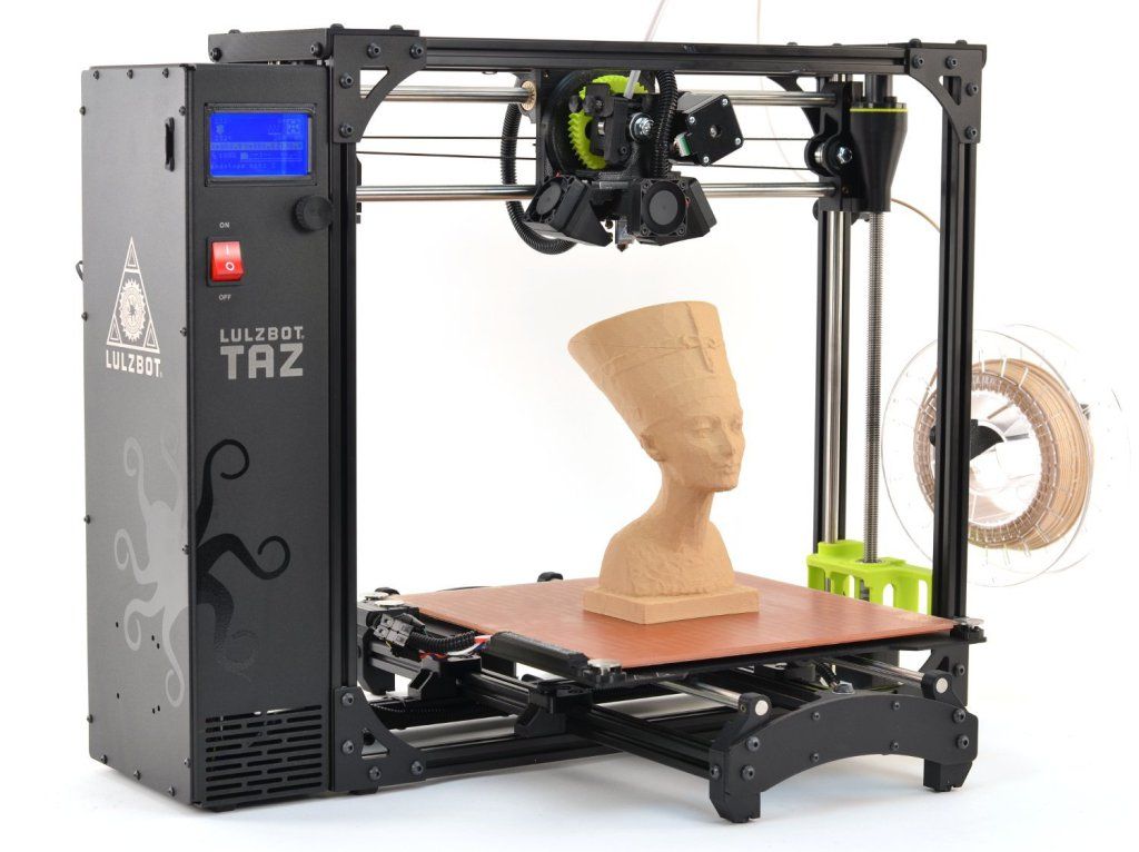
- 3D Printer: We’re using the Creality Ender 3 Pro, a solid entry-level 3D printer. However, other filament-based (aka FDM) printers should work similarly. If you need to choose, see our list of best 3D printers.
- Filament: PLA is one of the most commonly used materials on the Ender 3, and in this article we’ll be using Begonova branded material.
- 3D Model: The 3D Benchy is an ideal first print for your 3D printer; it offers a calibration test and is a fun model in a single print.
 However you can also download STL files from sites such as Thingiverse.
 - Slicing Software: In order to print your model, you’ll need to convert it from a solid 3D model to a series of slices that can be printed using an app called a slicer. We’ll be using Creality Slicer for this article, but most slicing apps offer similar features and the basic principles are the same.
- microSD Card: The Ender 3 Pro includes an 8GB microSD card for transferring files, but some printers include a USB drive. Most sliced gcode files will be between 5MB and 15MB, so anything over 1GB should work fine.
Getting Started
Before we get started, you’ll need to download both your 3D model as well as the slicer software for your 3D printer.
- Download the 3D Benchy model from Thingiverse, an online repository of 3D models that doesn’t require an account to download files.
- Download the slicer software for your 3D printer. We’ll be using Creality Slicer for the Creality Ender 3 Pro, but other common slicers include Cura, PrusaSlicer, and Simplify3D.
Picking a Model to 3D Print
(Image credit: Thingiverse.com)The 3D Benchy model by CreativeTools is a great first print that will help you dial in the settings on your 3D printer and also leave you with a fun tugboat model to show off! The Benchy model typically prints in about an hour and a half, and many of the features and details of the model can be used to identify and diagnose any mechanical issues on your printer such as loose belts, inadequate part cooling, and Z-offset calibration. However, these instructions should work for other STL files you find on Thingiverse, including Plunderbuss Pete, Aquaticus the Water Dragon and Adalinda the Singing Serpent, all of which are great models for your first 3D print.
(Image credit: Creality)Creality Slicer accepts 3D models that use the . STL file extension, a common extension used for 3D models. Once you’ve downloaded the model, import it into Creality Slicer by opening the app and clicking File, Load Model File, and selecting the 3D Benchy model from the folder where you downloaded it. This will load the 3D model into Creality Slicer so it can be prepared for 3D printing.
Preparing the Model for 3D Printing
Once the model has been imported into the slicer app, we can convert the .STL file into a 3D printable file. A 3D printable file contains all of the instructions needed to turn the .STL 3D model into a printed part by controlling the XYZ motors, extruder, and heating systems of the printer.
(Image credit: Creality)Creality Slicer offers two modes for slicing .STL files: Quickprint and Full. Quickprint allows you to choose a material, profile, platform adhesion aid and also toggle support material on and off. While the Full mode offers more granular control over the print settings, we’re going to use Quickprint for this article so we can cover all the basics. Here’s what to choose on the menu:
- Material: This is the material being used for the print. Since we’re using PLA, we’ll select ‘Common PLA’ here.
- Profile: Selecting a profile automatically adjusts all of the settings used in making a print including layer height, print speed, travel speed, etc. While these settings are all individually adjustable in the Full mode, selecting a premade profile will get you printing quickly without much adjusting required. We’re going to use ‘Normal (0.15,mm)’, which strikes a good compromise between speed and quality.
- Other: The only option here is to toggle support material on and off. Because the 3D Benchy doesn’t require support material, we can leave this box unchecked.
- Platform Adhesion: Creality Slicer can automatically generate a brim or raft to aid adhesion when using high-temperature materials that tend to warp or curl during printing. Since we’re using PLA, we won’t need to select either of these options and can leave this drop-down menu set to ‘None’.
Toggling ‘Full’ mode on will reveal more adjustable parameters. By selecting the ‘Normal’ Quickprint setting, these settings will all be populated accordingly. While we’re not going to be adjusting any of these settings, it’s worth taking a minute to better understand what they all do.
(Image credit: Creality)The default values in the above picture are a great place to start, but you can always adjust them in your slicer software if you want to make changes. Some of the terminology may change slightly in different slicer apps, but these settings are generally the same across most common apps.
Quality
- Layer Height: Thicker layers will print more quickly, but they won’t capture as much detail as thinner layers.
- Shell Thickness: Printing a model with a thicker shell will create additional contours on the outside of the model, which can look better on sloping surfaces but will take longer to print.

- Enable Retraction: By enabling retraction, the printer will pull the filament back into the nozzle when moving, preventing stringing or blobbing between travel moves. Too much retraction and the filament may be damaged by the drive gear, too little and the material may ooze during printing. Dialing in retraction can be a time-consuming process, and it may not be needed depending on the type of 3D printer you’re using.
Fill
- Bottom/Top Thickness: Adding additional layers to the top and bottom of the print can help to hide the internal fill pattern, but will also take longer to print.
- Fill Density: Also known as infill, this setting controls the amount of material printed inside the model. Adding infill can make a part stronger, but will take longer to print. The default setting of 15% is a good starting value if you’re looking to experiment.
Speed and Temperature
- Print Speed (mm/s): Increasing your print speed will lead to faster prints, but the overall quality of the model can suffer if this is increased too much.
- Printing Temperature: Most PLA material will extrude at 200C, but sometimes you may want to increase or decrease this value for best results. Too hot and the heat will creep up the filament and cause it to soften and deform, too cold and the material won’t have time to get up to temperature and extrude through the nozzle.
- Bed Temperature: When using a heated bed, enabling this setting will help the material stick to the bed without curling or warping during printing. Similar to the case with the nozzle temperature, setting this too low won’t provide any specific benefit but setting it too high may cause the filament to soften and deform on the lower layers.
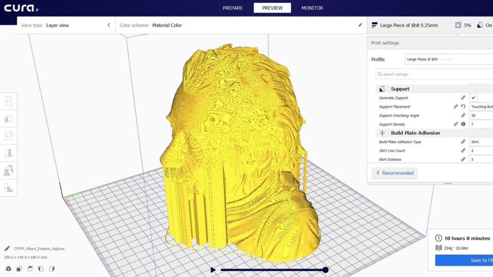
Support
- Support Type: The three settings in this dropdown menu are None, Touching Build Plate, and Everywhere. None will print a model without generating any support material, Touching Build Plate will only generate support material that originates on the build plate (for instance, an upright letter T would be supported fully, but an upright letter E would not), and Everywhere will create support material everywhere on the print.
- Platform Adhesion Type: Selecting None will print the model flat on the build plate, Brim will add a few toolpaths of material around the base of the model to help keep it from curling, and Raft will add several layers of material under the model to compensate for an uneven platform.
Filament
- Diameter: PLA filament is typically sold with a 1.75mm diameter, so this setting shouldn’t be changed unless you are using non-standard material.
- Flow: This setting adjusts how much material is fed through the extruder, and typically shouldn’t be changed unless your printer hasn’t been calibrated correctly.
Machine
- Nozzle Size: The Creality Ender 3 Pro (and most desktop 3D printers) ship with a .4mm nozzle, so this setting shouldn’t be changed unless you have swapped out the nozzle for a smaller or larger one.
Checking the Toolpath for 3D Printing
You can see the difference in the three Quickprint profiles in the above pictures (Fast, Normal, and High Quality). A quick way to spot the difference is by looking at the roof of the Benchy, where the number of layers increases with each jump in quality. Thinner layers will capture more detail but the overall print time will increase as well. The Normal setting strikes a compromise between speed and quality, so that’s the setting we’ll choose.
After you’ve chosen the settings for your model, the slicer software will generate a toolpath (instructions for the printer’s movement system) for your model. We can see this toolpath by selecting ‘Toolpath’ in the dropdown menu under the ‘View Mode’ button at the top right. This is a good time to check the file before printing, and make sure there are no areas that might cause problems later. Scrolling through the layers we can see the infill and outer shell, and determine that this model is ready for printing.
Preparing the 3D Printer
Once the model has been sliced and is ready for export, it’s time to make sure the printer is ready to print. There are two major components to this process: loading the PLA filament into the extruder and calibrating the build platform. Loading the filament gives the printer material to complete the print, and calibrating the build platform ensures that the nozzle is perpendicular to the build plate at all points and compensates for any warp or bowing present.
The steps here are for the Creality Ender 3 Pro, but any 3D printer with a Bowden extruder (remote drive) will use a similar process for loading filament and calibrating the build platform.
(Image credit: Tom's Hardware)Loading the PLA filament
- Turn on your 3D printer.
- Select Preheat PLA on the printer menu to bring the nozzle up to the correct temperature.
- Place the spool of PLA material on the spool holder, taking care not to let the material get tangled on itself.
- Insert the filament into the extruder by pushing on the spring-loaded lever and push the filament until you see it coming out of the nozzle.
Image 1 of 2
(Image credit: Tom's Hardware)(Image credit: Tom's Hardware)Calibrating the Build Platform
- Select Auto Home on the menu screen to automatically bring the printer to 0 on the X, Y, and Z axes.
- Once the printer has run the homing routine, select Disable Steppers to allow the gantry to be moved by hand.
- Slide a standard piece of printer paper between the nozzle of the printer and the build platform.
- Bring the print head to the front right corner of the build platform and adjust the thumbscrew until you feel a slight resistance when moving the piece of paper between the nozzle and the build plate.
- Repeat Step 4 for the front left, back left, and back right corners.
- Once you feel a slight resistance across the build platform, remove the piece of paper and visually verify the small gap between the nozzle and the build platform at all points on the build plate.
Printing the 3D Model
Once the model has been sliced and the 3D printer has been prepared, the next step is export the sliced model as a .gcode file. The Creality Ender 3 Pro uses a microSD card for transferring .gcode files from your computer to the printer, and Creality Slicer will export the file directly to the card. This prepared file was 5.8MB, which fits easily on the 8GB microSD card which came with the Ender 3 Pro.
(Image credit: Tom's Hardware)After calibrating the build platform and making sure the filament is properly loaded, we can insert the microSD card and get the print started. The Benchy print takes about one hour and 45 minutes to print using the Normal profile, and you should be left with a fun-looking boat that doubles as a calibration test. Once printed, you can remove the Benchy by removing the flexible build plate from the Ender 3 Pro and bending it, which will allow the printed model to pop right off.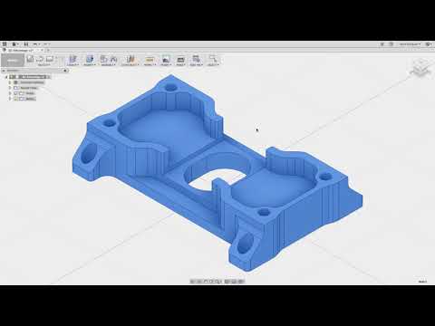
Some things to look for on your first print are curled edges on the base of the print (which could indicate a problem with print temperature or speed), a rough looking outer surface (which could indicate a too-thin shell), or stringing between the cabin walls (which could indicate an issue with temperature or retraction). Half the fun of owning a 3D printer is making adjustments and dialing in your print quality, so now you’re well on your way to converting .STL 3D models to 3D prints.
Get instant access to breaking news, in-depth reviews and helpful tips.
Contact me with news and offers from other Future brandsReceive email from us on behalf of our trusted partners or sponsorsAndrew Sink first used a 3D printer in 2012, and has been enthusiastically involved in the 3D printing industry ever since. Having printed everything from a scan of his own brain to a peanut butter and jelly sandwich, he continues to dive ever more deeply into the endless applications of additive technology.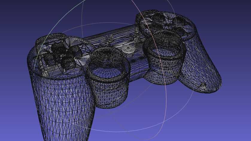 He is always working on new experiments, designs, and reviews and sharing his results on Tom's Hardware, YouTube, and more.
Topics
3D Printing
STL format and 3D printing
Categories
- News list
- STL format and 3D printing
Description and features of the STL format
Today, the STL format (simulation file for stereolithography) is becoming increasingly popular. Its development was carried out for the needs of stereolithography (volumetric lithography), and was intended for rapid prototyping and visualization of three-dimensional models. The format describes the triangles that make up the outlines of any object. Its main difference from other formats is ease of use. To represent the shape of a digital 3D STL model, a sequence of triangles is applied. nine0005
There are two structures of STL formats: text and binary. The binary structure of the STL file of the model is more compact, requires less space, and has greater accuracy. But the use of a text structure allows the transfer of files to a computer with a different representation of numbers, and the number of characters for each number can be arbitrary. At the beginning of the text file of the STL program, the keyword "solid" must be present. The following is a brief explanation about the object and its manufacturer. Then the triangles themselves are described, for which unit normal vectors and a Cartesian three-dimensional coordinate system are used. The end of the file is marked "endsolid". nine0005
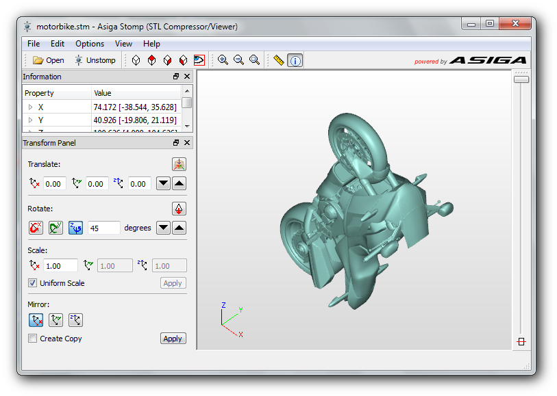
Converting to STL format
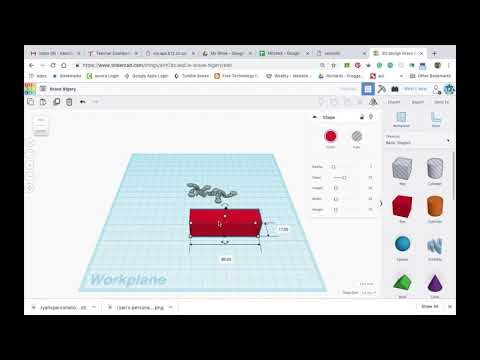
When meeting with STL, many people ask how to open this format. Your best bet is to use the Microsoft Internet Information Services (IIS) program. There are several other programs: MeshLab, Geomagic Explorer, Dassault Systemes CATIA and others. To edit the STL format, any 3D editors and CAD programs are used. 3D printing is taking us to a new reality, but in order to print anything, any 3D printer needs instructions. There are STL files for this. nine0005
All STL models for the printer include hundreds or even thousands of horizontal layers that will overlap until the 3D object is printed. Typically, such files are either written from scratch on their own, or ready-made ones are used, created using various 3D modeling programs. If you have not yet mastered the construction of three-dimensional objects with the nuances of conversion, it is easier to turn to ready-made 3D models. To do this, there are several free services on the Internet, such as: thingiverse.com., kraftwurx.com. and others. nine0005
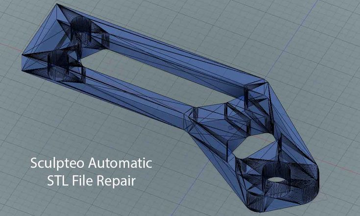
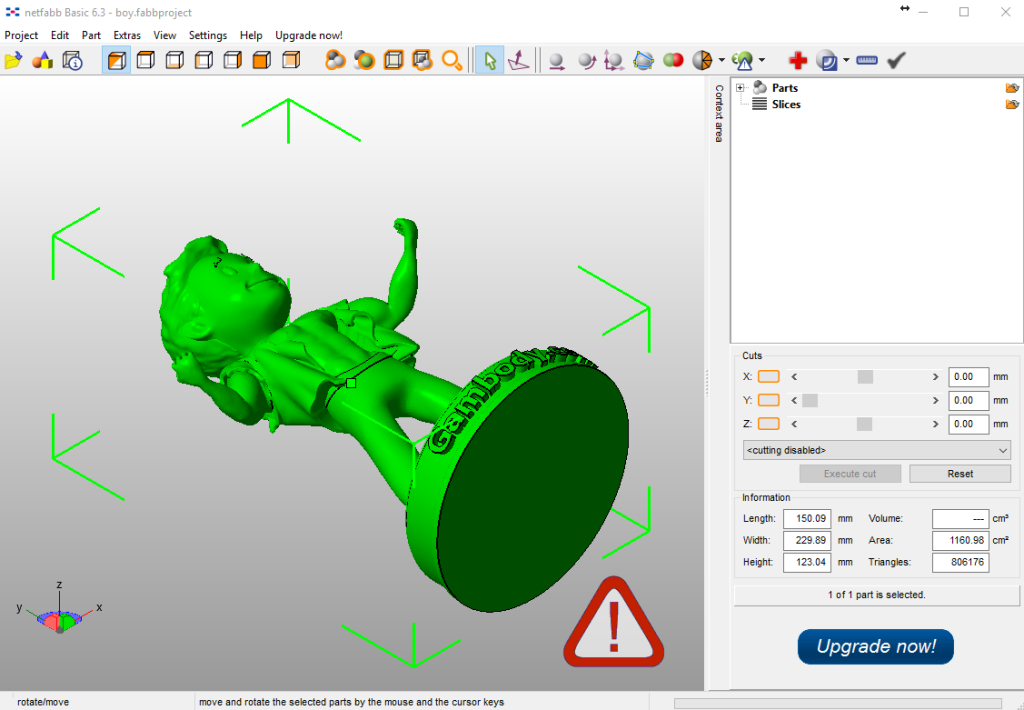
Errors in the STL file
Your 3D printer will print the proposed material without any problems, but to get a high-quality result, you need to take into account one more small feature of the technology. When you export for printing, selected or created models in STL format, holes often appear on them, preventing the models from becoming solid. To avoid these problems, use the NetFabb cloud server. Send the file to it, and when it is fixed, check it with the STLView viewer, and only then resort to printing. We wish you success! nine0005
'; } html += '
'; html += '
' + json[i]['label'] + '
'; html += '
' + json[i]['special'] + '
'; if(json[i]['special']){ html += '
' + json[i]['price'] + '
'; } else { html += '
' + json[i]['price'] + '
'; } html += '
3D printing STL files: step by step guide - 3DPrinter
3D printing STL files: step by step guide in additive technologies. Information about an object is stored as a list of triangular faces that describe its surface, and their normals. The STL file can be text (ASCII) or binary. It got its name from the abbreviation of the term “Stereolithography”, since it was originally used in this particular 3D printing technology.
 nine0005
All modern CAD (Computer Aided Design) programs allow you to export your own file format to STL. The 3D model is then converted into machine language (G-code) through a process called "slicing" and the model is then ready to be printed.
In this article, you will learn the basic steps required to properly export your models for 3D printing .
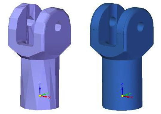
Step 1: Resolution STL
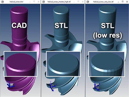
The STL file format uses a series of linked triangles to recreate the surface geometry of a solid model. Increasing the resolution will use more triangles, better approximating the surfaces of the 3D model, but also increasing the size of the STL file. nine0005
If you export the file at too low a resolution, the model will have visible triangles on its surface when printed. In most cases this is not desirable, but they can be used to create "low poly" models with a digital look.
Increasing the resolution above a certain point is also not recommended, as it does not bring any additional benefit: very small details cannot be 3D printed, so the file size will be increased unnecessarily, making subsequent processing difficult.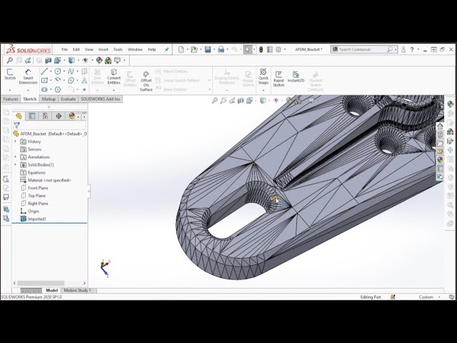 nine0005
Step 2: Export Options
You can change the resolution of STL files by changing the format options in the software. If you're unsure, choosing preset is the safest option to create an STL file that fits 3D print .
Each CAD package has different STL resolution options, but most use two main parameters: chord height and angle.
Chord Height is the maximum distance between the surface of the original 3D model and the surface of the STL file that the software can use. Using a lower chord height will help show the curvature of the surface more accurately. nine0005
The recommended value for the chord height is 1/20 of the thickness of the 3D printed layer and not less than 0.001 mm (1 micron). This will always produce an STL file with perfect accuracy for most applications 3D printing . Exporting at a lower tolerance will not affect print quality, as most conventional 3D printers are not capable of reproducing such a high level of detail.
Angular tolerance limits the angle between the normals of neighboring triangles. The default value is often 15 degrees. Some programs also specify this tolerance as a value between 0 and 1. If a smoother surface does not require a higher setting, the default value of 15 degrees (or 0) is recommended. nine0005
Step 3: Export STL files from your CAD software
Let's see how you can quickly and easily convert your file to STL format in different programs.
AutoCAD:
Important: Export to STL format is only possible for entire 3D objects
- Enter “FACETRES” on the command line
- Set parameter FACETRES to 10.
- Enter command “STLOUT”
- Specify objects to export
- Press Y or Enter at the Create a binary STL file? [Yes/No]
- Specify file name
- Save the file.
Autodesk 3ds Max (3D Studio Max)
- Open the File > Export tab)
- Select file type - StereoLitho *.
 stl
stl - Enter file name
- Save file
- Select type Binary
- Press OK
Autodesk Inventor / Mechanical Desktop
Important: you can export both individual parts and whole parts of the model
- Open Manage tab > Update panel > Rebuild All
- Then open File > Save as > Save Copy As
- Select STL file format
- Enter file name
- Set the following parameters: Format - binary (Format > Binary), units - mm or inches (Units > mm, inches), resolution - high (Resolution > High)
- Save file
Google Sketchup
If you are using Sketchup Standard and not Pro, you will need to install a special extension to export to STL. You can find the appropriate extension for your version of Sketchup here. Download the extension, go to Sketchup > Window > Preferences > Extensions > Install Extension to install it. nine0033 To export to STL after installing the extension, follow the instructions below:
- Go to Sketchup > Tools > Export to DXF or STL
- Select the desired object to export.
 If you do not select an object, then the model will be exported completely.
 - Select the units of measurement for the exported object: meters, centimeters, milimeters, inches, feet
- Select the geometry of the exported object: polyface mesh, polylines, triangular mesh, lines, stl
- Select where you prefer to save the exported file.
Attention: if you export a circle with this plug-in, then when you view it in some other programs, you will notice that when you increase it, it consists of short segments.
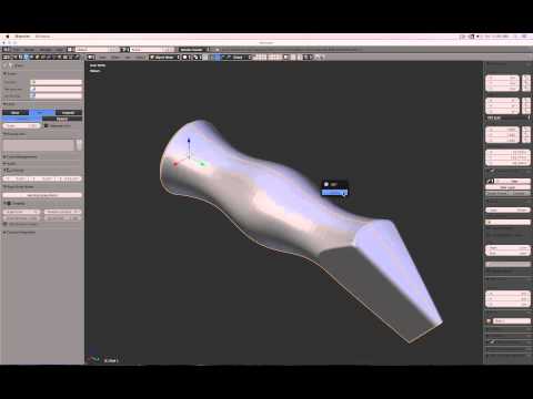
Blender
- Go to File > Export > STL
- Enter file name
- Specify file locations
- Press the Export STL button
Pro ENGINEER
- Open File > Save a Copy
- Select STL type and press OK
- Set Coordinate System Standard
- Select file format Binary
- Set the following parameters Chord Height to 0 (set the minimum allowable Pro/E values)
- Angle Control leave default
- Enter file name and press OK
Rhino
- Open the File > Export Selected or File > Save As tabs
- Select objects to export
- Set file type to Stereolithography (*.
 stl)
stl) - Enter file name
- Save file
- In the STL Mesh Export Options window, set the Enter Tolerance to 0.02 mm (0.0008 inches), then click OK.
- Set file format to Binary
- Uncheck the Uncheck Export Open Objects option
- And press OK again
Solidworks
- Go to File > Save As…
- Set the file type to STL(*.stl)
- Open the Options tab
- Set the output file format to Binary
- Units - millimeters or inches (Unit: > Millimeters or Inches)
- Resolution-Good (Resolution > Fine)
- Press OK
- Enter file name
- Save
SolidWorks Student Design Kit
- Go to File > Save As…
- Set file type eDrawings(*.eprt)
- Open the Options tab
- Check the box Allow export to STL for Parts & Assemblies
- Press OK
- Enter file name
- Save file
- Open the file in eDrawings
- Open the tabs File > Save as… > and set the file type to STL (*.
Learn more