How tight should 3d printer belts be
How to Properly Tension Belts on Your 3D Printer – Ender 3 & More – 3D Printerly
There are several factors that affect 3D print quality, one of those things being your belt tension. If you aren’t sure about how to properly tension the belts on your 3D printer, this article will guide you through that process.
The best way to ensure you properly tension your 3D printer belts is to tighten it so it hasn’t got any slack and has some resistance to being pushed down. It should be around the same tension as a stretched out rubber band, but don’t tension your belts too tight because it can increase the wear on the belt.
The rest of this article will detail the best process to figure out how tight your belt tension should be, as well as other useful information regarding this topic.
A Guide on How To Properly Tension/Tighten Your 3D Printer Belts
The proper technique to adjusting your printer belt tension does vary across printer brands and styles, since many 3D printers are built differently, but there are similarities.
It’s a good idea to first figure out how your 3D printer works and how the belts are joined on the X & Y axes. For this article, I’ll be talking about how you tighten an Ender 3 belt.
The X-axis belt runs directly through the extruder, and the extruder is attached to a motor that allows it to move back and forth across the X-axis belt. Some methods which can be followed are explained below to adjust the tension of the printer belt.
Tighten Screws on X-axis: In most printers, the belt is attached to X-axis and a pulley that is further attached to a motor shaft to maintain tension in the belt.
If you look closely, you will find screws on both sides of the X-axis. Tighten these screws as it helps you in getting the right tension in the belt of the printer.
Adjust the Tensioner: To adjust the tension, you will require a hex key that comes with the printer. The remaining process is given below.
How Do You Tighten an Ender 3 Belt
- Loosen the two nuts that hold the tensioner in place
- Use the larger hex key and slide it down between the tensioner and the x-axis extrusion rail.
- You can now use this as a lever to apply force on the tensioner and keep it as far out as possible to keep the belt tight.
- At that moment, tighten the bolts back up on the tensioner
- Once it is done, you can repeat the same process on the Y-axis.
Adjusting the Belt Tension at Y-Axis
Adjust the belt tension on your Y-axis works the same way as on the X-axis, but usually it doesn’t require as much tension adjustment.
Your printer belt is moved through stepper motors from one side to the other, and they don’t usually need replacing if treated right, unless it’s been years. Over time, they can stretch and break, especially if used constantly.
The video below shows a nice visual on tensioning an Ender 3 belt, which you can do for the Y-axis.
If you would rather choose an option that allows you to tension your belts with ease, I’d consider getting yourself the UniTak3D X-Axis Belt Tensioner from Amazon.
It fits around the end of your 3D printer on the 2020 aluminum extrusion, but instead, it has a wheel tensioner to make the job easier. It’s very easy to install and requires no assembly!
You can also get the BCZAMD Y-Axis Synchronous Belt Tensioner from Amazon to have the same functionality on the Y-axis.
How Tight Should My 3D Printer Belt Tension Be?
Your 3D printed belt should be relatively tight, so there is a good amount of resistance, but not so tight that you can barely push it down.
You don’t want to over-tighten your 3D printer belt because it can cause the belt to wear out a lot quicker than it would have otherwise. The belts on your 3D printer can be pretty tight, to the point where getting underneath it with an object is fairly difficult.
Below is a little visual on how tight the Y-axis belt is on my Ender 3. Getting the belt to this position takes a decent amount of push and that is really stretching it, so you can look towards having your belt around the same tightness.
You can gauge belt tension pretty well by watching a video and seeing how tight it looks and springs.
A loose belt can result in skipped layers and is very likely to decrease your print quality, so I’d advise making sure you have it at a good resistance level.
Make sure to move the X and Y axis slowly from one end to the other to make sure the belt is in good working order and not rubbing hard on the aluminum extrusion.
How Do You Know If Your 3D Printer Belt is Tight Enough?
Setting the proper tension in the belt is all about trial and error. However, there are many manual ways to find the belt’s tension and tighten it until you feel satisfied.
Some methods that are commonly followed to check the tension of the belt:
- By touching the belt to check the tension
- Listen to the sound of a plucked belt
This is one of the easiest ways to test the printer belt’s tension as it would only require fingers and sense to feel. If the belt is pressed with the fingers, they should be tight enough to move very little; if not, the belt must be tightened then.
Listening to the Sound of a Plucked Belt
The sound that emits from your belt after plucking it should sound like a twang, similar to a low-note guitar string. If you don’t hear any note or a lot of slack, it’s likely that your belt isn’t tight enough.
How to Fix A 3D Printer Belt Rubbing (Ender 3)
You can sometimes experience your 3D printer belt rubbing against the railing, which isn’t ideal. It can create plenty of vibrations throughout the axis, resulting in poorer surface finishes on your models.
Luckily, there are a few ways to fix this.
A solution that you can try is having the belt tightener at a downward angle, allowing the belt to get low enough to get space on the metal. This works because there is still some up and down motion after tensioning your belts.
So basically tilt your belt tensioner downwards so it runs below the lip of the railing.
Once your belt is below the part of the rail which it rubs against, you can fully tighten the two T-nut screws that hold the pulley in place.
Something that has worked for many users is using either a spacer or installing a 3D printed Belt Tensioner from Thingiverse for their 3D printers.
Another user who had the same issue of their 3D printer belt rubbing on an Ender 3 was to turn the bolt itself a quarter of a turn at a time, then testing whether it ran smoothly until the belt ran center.
One guy had some luck by replacing the thin nut on the left with two M8 washers and an M8 sprung washer. After implementing this, their belt ran perfectly fine.
Ender 3 x axis fix
Best Ender 3 Belt Upgrade/Replacement
A good Ender 3 belt replacement that you can get yourself is the Eewolf 6mm Wide GT2 Timing Belt from Amazon for a pretty good price. Many reviews talk highly of this belt for good reason.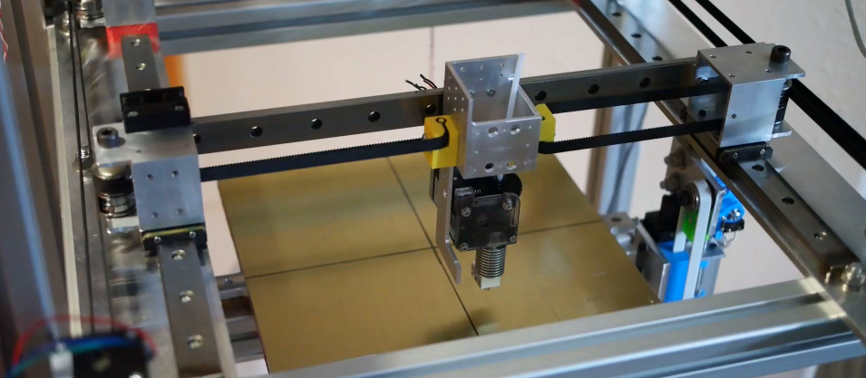
The rubber material is a high strength synthetic rubber called Neoprene, along with glass fiber throughout. It can comfortably be used for your X-axis and Y-axis and you’re getting 5 meters of belt so you can replace it easily when needed.
Ender 3 (Pro/V2) Belt Tension; How tight should they be? – 3D Solved
In this article, I will be going over a lot of the important information regarding the belts on your Ender 3 and how tight they should be.
I will also show you results of three different prints I made, one with very loose belts, another one with fairly tight ones, and the last one with the belts as tight as possible so you can actually see the results for yourself, and in fact one of them didn’t even work!
Lastly, I will show you how to properly tension the belts and also where to get proper belt tensioners for your Ender 3 and Ender 3 Pro (Ender 3 V2 already comes with tensioners) to make this whole process easier.
So, how tight do the belts on an Ender 3 need to be? The belts need to be as tight as possible without any slack to prevent the printer from skipping gears, and as long as the belts don’t break or get stretched, the tighter the better since this will improve the overall print quality.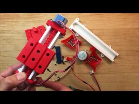
If you don’t want to have to go through all the trial and error that we did in order to find the Ideal Settings for creating high-quality prints on your Ender 3, then definitely check out our own Cura Profiles tailored specifically for the Ender 3 Printer Series.
Print Quality difference between Loose and Tight Belts
I loosened the belts quite a lot simply to test this out and wanted to show you just how loose both the X-Axis and Y-Axis belts were. So, here’s a picture where you can clearly see how much I loosened them:
Left: X-Axis Belt very loose.Right: Y-Axis Belt also very loose.
Now, on to the results:
Like I just mentioned, the tighter the belts the better, but you probably want to be able to see the results for yourself, so here’s how these 3 20mm cubes printed:
Cube 1: Belts too loose which caused the belts to skip gears.As you can clearly see from the first cube I attempted to print, since the X Axis belt was so loose it ended up skipping some gears and the whole cube shifted to the left.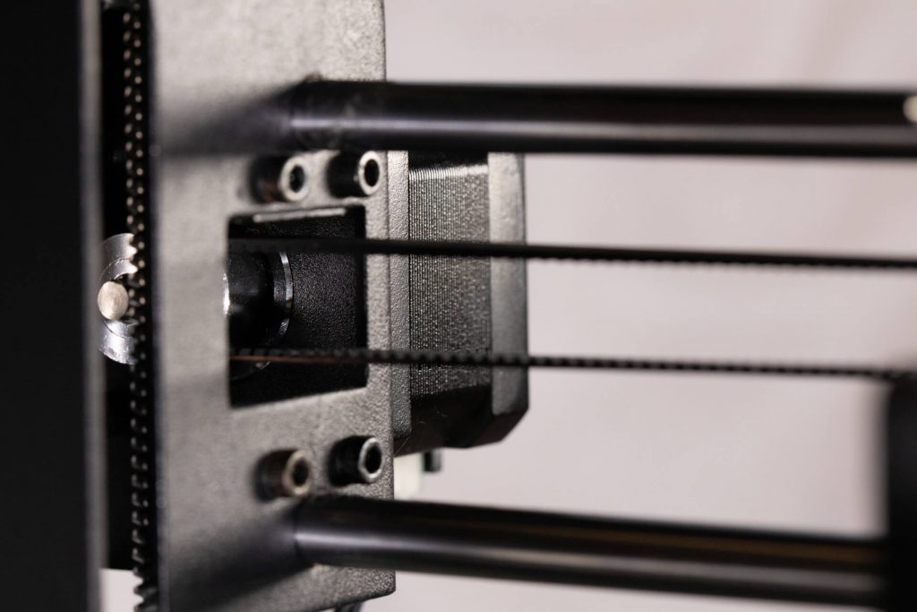
This is very common when printing with a loose X Axis belt but it’s really simple to diagnose and fix since it’s you can clearly see what’s happening.
Left: Cube 2 printed with fairly tensioned belts. Clear visible waves.Right: Cube 3 printed with the belts as tight as possible. No visible waves, layer lines are also less visible.
With Cubes 2 and 3 you can clearly see how belt tension can affect the print quality since those waves on Cube 2 aren’t at all visible on Cube 3.
Poorly tensioned belts can also cause your prints to come out with more visible layer lines than they should, and while this could also be because of inconsistent extrusion, most people don’t think of this as being caused by the belts and completely forget to check them.
Here’s one example taken from the Tomb of 3D Printed Horrors YouTube Channel:
Left: X-Axis belt fairly tight.Right: X-Axis belt extremely tight.
As you can see, the quality of the print on the right is much better and those same super visible layer lines aren’t present.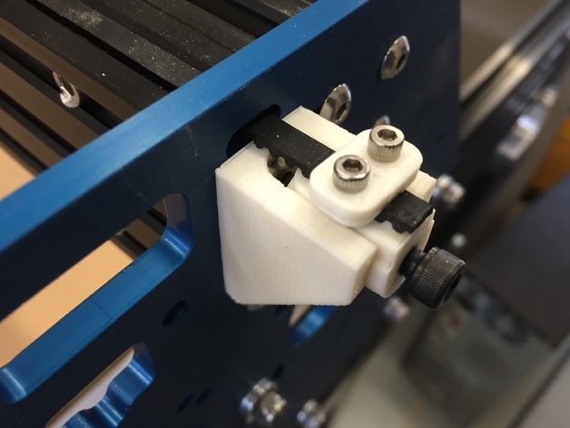
Can the Belts on the Ender 3 be too tight?
As long as the belts don’t break or get stretched out, they should be as tight as possible to achieve the best printing quality the printer has to offer and to avoid skipping any gears accidentally, which will shift the upcoming layers to one side creating a stair stepping effect.
It’s worth noting, however, than ruining the belts by tightening them too much is a real possibility, and while you should do your best to tighten them as much as possible, do so with care.
Next, I will explain how to adjust the tension on both belts on the Ender 3 using the provided tools which is fairly simple but won’t let you tighten them as much as you could with dedicated belt tensioners. However, I will also show you where to get those tensioners and how to use them, should you be interested.
How to adjust the Belt Tension on an Ender 3 (Pro and V2)
Generally, the Y Axis belt tends to come pretty tight right from the factory, in fact, mine was perfect and I had to loosen it up to be able to test how it affected print quality when loose. However, the X Axis belt is the one that you have to install and this is where things might go wrong.
So, generally speaking, your X Axis belt will be the one requiring attention, not the other one.
How to adjust the X Axis belt on an Ender 3:
You will only need one tool to do this, which is the second largest Allen Key that came with the printer.
- Loosen the two screws on the idler on the far-right side of the X Axis.
- Pull on the idler to tension the belt and hold it there with one hand.
- Tighten the screws again making sure the idler is parallel to the X Axis.
When I first assembled my printer, I didn’t do that great of a job at tightening the X Axis belt and my first print skipped gears and got ruined. Luckily, it was right at the start of the print, but loose belts can definitely ruin the entire process and if it happens near the end, it’s no fun at all!
How to adjust the Y Axis belt on an Ender 3:
This one is a bit tougher to tighten because there’s a lot more screws holding the entire bracket and if you’re doing it by hand, you’ll need to really pull on it to get it tight enough.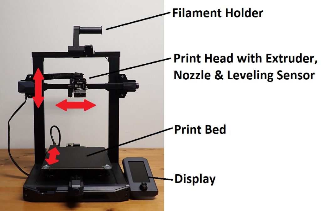 Still, you’ll need the same Allen key as before.
- Loosen all four screws on the side of the bracket using the provided Allen Key.
- Pull on the bracket to tension the belt.
- Tighten the four screws while still pulling on the bracket to keep the belt from loosening up.
Belt Tensioner Upgrade
There are multiple versions of these belt tensioners available and you could certainly go with any of them since the way of using them is fairly similar since they will allow you to easily adjust the tension by twisting a knob.
However, it’s worth noting that the Ender 3 and Ender Pro, as well as the V2, have different width Y Axis, so make sure to get the one that is right for your printer.
Once you installed them, simply turn the knob clockwise to tighten the belts and counter-clockwise to loosen them.
Recommendation: Tighten them really hard and them give them about half a turn counter-clockwise to just very slightly remove some tension off the belts in order to keep them from stretching.
Example of Belt Tensioner (Sold on Amazon).
If you don’t want to have to go through all the trial and error that we did in order to find the Ideal Settings for creating high-quality prints on your Ender 3, then definitely check out our own Cura Profiles tailored specifically for the Ender 3 Printer Series.
Conclusion
Clearly, loose belts can completely ruin your prints, and even belts that aren’t tight enough will cause some visible layer lines and waves to be present on the as well.
I’d recommend tightening them up as much as possible as long as you’re not damaging the belts, since this will improve the print quality of your Ender 3 by quite a lot and also make it more reliable.
Getting belt tensioners might help, but I honestly think that you can manually tension the belts on the stock Ender 3 configuration and achieve the same results, even though it might be harder to tighten them properly.
I hope this information was useful!
Have a great day!
We created a recommended products section that will allow you to remove the guesswork and reduce the time spent researching what printer, filament, or upgrades to get, since we know that this can be a very daunting task and which generally leads to a lot of confusion.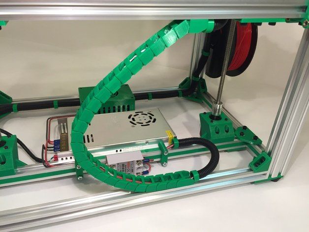
We have selected just a handful of 3D printers that we consider to be good for beginners as well as intermediates, and even experts, making the decision easier, and the filaments, as well as the upgrades listed, were all tested by us and carefully selected, so you know that whichever one you choose will work as intended.
How the belt tension of the Ender-3 (Pro/V2) 3D printer affects print quality. How to properly tighten them.
In this article, we're going to look at some pretty important and useful information about the straps on Ender 3 (Pro/V2) 3D printers and how tight they should be.
We will also look at the results of 3D printing in three ways: one with loose belts, one with tight belts, and one with optimal belt tension.
This will give you a visual and understanding of the importance of keeping the printer belts tight and the impact they can have on your print quality. Looking ahead, let's say that in one of these cases, printing a part turned out to be an impossible task.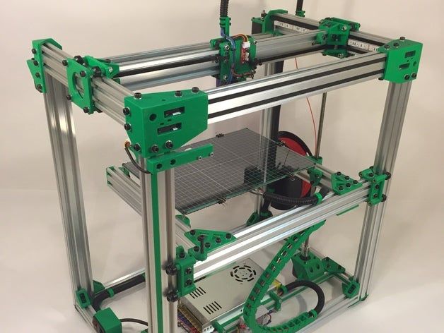
Of course, we will also tell you how to properly tension the belts, as well as where to find convenient tensioners for Ender 3 and Ender 3 Pro (Ender 3 V2 already comes with tensioners) to make the whole process easier.
How tight should the straps be on the Ender 3?
Only trial and error will help determine the correct belt tension.
First check the belt to make sure it is tight and not slipping off the pulleys. You should feel some resistance as you squeeze the top and bottom of the belt.
You must pull the belts as tight as possible to prevent slack, otherwise your belt will slip and the printer will skip.
After tensioning the belts, be sure to carry out a test. To do this, print some simple model, a small test cube is best for this. If you still see ripples, layering, or some other negative effect on the surface, it might be worth checking the tension again.
If your belt is too tight, it can cause you to skip steps, overheat the engine and prematurely wear out the mechanics.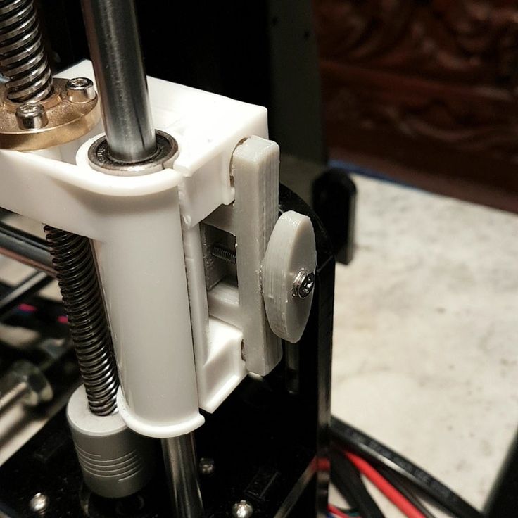 An overtightened belt will cause unusual deformations on your part.
Also note that belts that are too tight are subject to faster wear and in some cases may even break.
Some signs that you need to check the belts on your 3D printer:
- Loud sounds coming from the printer.
- Your belt appears to be loose when you look at it.
- Parts are rippled and/or deformed
- Your printer stops for no apparent reason.
Inspecting the printer will allow you to locate the problem. Similar effects can be caused by other reasons, however, do not forget to check the degree of tension of the belts.
Difference in print quality between loose and tight straps.
We have loosened the belts enough to show you the quality of the 3D printer with the X and Y belts loosened.
3D printed results.
Cube 1: The belts are too loose, the efficiency of the transmission chain is reduced, as a result the entire cube has shifted to the left.
This phenomenon is quite common when 3D printing with a loose X-axis belt, but it can be easily diagnosed and corrected because you can clearly see what is happening.
For Cube 2, we tightened the straps, but not tight enough. Layers and waves are clearly visible on the model.
Cube 3 printed with optimally tensioned straps. The print quality has improved a lot, there are no visible waves, layer lines are also less visible.
With cubes 2 and 3, you can clearly see how belt tension affects 3D print quality.
Loosely tensioned belts can also cause your prints to show more visible layer lines, detracting from the appearance of your model.
This problem can be caused not only by weak belts, but also by uneven extrusion. However, in this situation, most people do not think that the reason is in the belts and forget to check the degree of their tension.
Another example of the difference in 3D printing quality between weak and tight belts.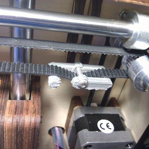
Can the belts on the Ender 3 be too tight?
For best 3D printing quality, 3D printer belts should be pulled as tight as possible without stretching or breaking.
Under-tensioned belts create a stepped effect on your part, and in the worst case completely distort its geometry.
However, it is worth noting that you can damage the straps when overtightening. So while you should do your best to tighten them as tight as possible, do so carefully.
In the next section, we'll show you how to adjust the tension on both belts on the Ender 3 using the provided tools, which is quite simple but won't allow you to tighten them as much as you could with the special belt tensioners.
How to adjust belt tension on Ender 3 (Pro).
The Y-axis belt is often tensioned at the factory by the manufacturer and is usually well adjusted. We had to loosen it on purpose to show you the print quality on loose belts.
You install the X-axis belt yourself, so something can go wrong here.
How to adjust the X-Axis Belt on the Ender 3.
You only need one tool for this, the second largest hex wrench that comes with the printer.
Loosen the two screws on the idler on the far right side of the X-axis.
Use a larger hex wrench and insert it between the tensioner and the X-axis guide.0002 You can now use it as a lever to apply force to the tensioner and hold it as far as possible to keep the belt tight.
Tighten the strap and, holding it with one hand, tighten the screws again.
How to adjust the Y-Axis strap on the Ender 3.
The Y-Axis strap is a little trickier to tighten because there are more screws holding the entire bracket in place, and if you're doing it by hand, you'll need to put in some effort to tighten it tight enough.
However, you will need the same hex key as before.
Loosen all four screws on both sides of the bracket using the included hex wrench.
Pull the tensioner to tension the belt.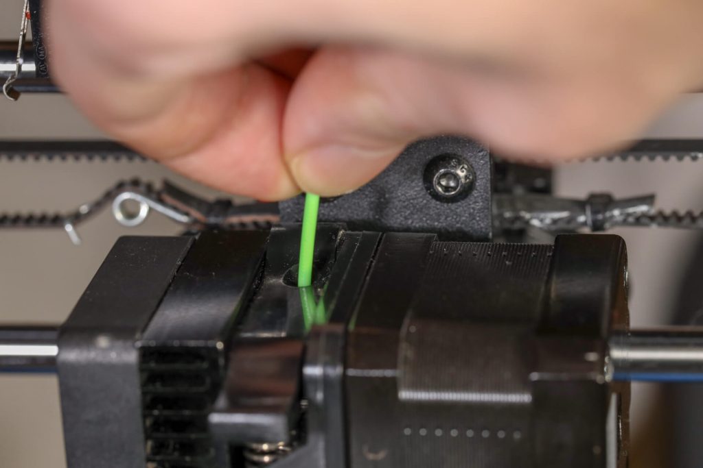
Tighten the four screws while holding the belt so that it does not loosen.
After adjusting the tension of the belts, make sure that the carriage moves smoothly along the X and Y axes from one end to the other, and the belt does not rub against the guides.
Installation of adjustable belt tensioners.
Adjusting the tension of the belts on the Ender 3 or Pro is a little trickier because, unlike the Ender 3 V2, earlier Ender 3s don't come pre-installed with adjustable belt tensioners.
Instead, Creality uses fixed belt pulleys that are at the ends of the X and Y axes and cannot be moved easily.
Fortunately, the Ender 3 development community, Creality and others have developed adjustable belt tensioners that allow you to change the belt tension on the axle by simply turning a knob. In this section, we'll look at how to upgrade your Ender 3 or Pro with an adjustable belt tensioner.
Belt tensioners are an efficient way to adjust belt tension without having to manually move the pulley on the axle.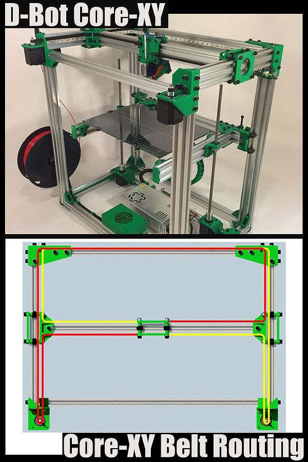
Ender 3 and Ender 3 Pro are very similar and the X-axis belt tensioner will work on both printers. However, since the Pro version has 40x40 Y-rails, while the original Ender 3 uses 20x40 rails, the Y-axis tensioner for the two printers is different.
Ender 3 Y-Axis Tensioner
Ender 3 Pro 9 Y-Axis Tensioner0003
X-Axis Tensioner for Ender 3 and Ender 3 Pro
It is important to note that in order to 3D print belt tensioners for Ender 3 or Pro, you must use print settings that will produce a strong and durable part. The belt tension will depend on the structural integrity and strength of the belt tensioner, so give it due consideration as you don't want it to break in the middle of the process.
Instructions for setting up the entire mechanics of a 3D printer: from belts to speeds
The quality of the printed models directly depends on the mechanics of the printer, namely on its correct settings. Any elements of the printer wear out over time, so the printer must be set up at least once every 5-6 kg of printed filament. With the help of the short instructions described in this guide, you can quickly and easily set up the mechanics of your printer: belt tension, motor current, motor steps, acceleration, jerk and speed.
Mechanics includes
3D printers of any design always contain the same things: Axes and rails along which the elements of the printer move and motors with belts that set these elements in motion. In a classic printer design, there are at least 3 motors (one for each axis), 3 rails (one for each axis) and an electronics board that controls the motors. The latter can hardly be called part of the mechanics, but since it controls the engines, it also indirectly affects the quality of the model.
Printing defects due to mechanical problems
Before changing anything in the printer, you need to decide what exactly needs to be configured. Often defects are visible visually. Our blog has an article about most printing defects, which details the reasons for their occurrence.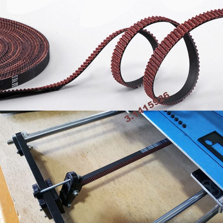 The following is a list of defects and what element of mechanics they are associated with:
-
Layer shifting - Belts, Motor current, Guides
-
Ringing - Guides, Speed
-
Incorrect model geometry - Guides, Motor steps, belts
As you can see, all the above problems do not interfere with the printing process itself, but the result leaves much to be desired. Sometimes mechanical errors can completely stop the printer from working. Therefore, it is better not to take the situation to extremes and, if any problems arise, immediately start checking and configuring the 3D printer.
How to save settings
To fix some defects, you need to change the printer software settings. Therefore, before adjusting the mechanics, it is necessary to understand how to properly store the settings inside the printer. There are 3 ways to do this:
All settings are located in the corresponding menu of the printer
Depending on your firmware, this manual will indicate code sections for MARLIN firmware in the configuration.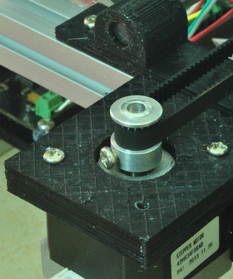 h file
We first enter the parameters into the printer and then store them in EEPROM - the internal memory of the microcontroller. Or paste all the necessary settings at the beginning of GCODE. To learn how to do this, read our article on working with GCODE and creating macros.
To save to EEPROM, you need to send the printer a command to change some value (which can also be inserted into the initial GCODE), and then send the M500 command (save the current settings to permanent memory). The EEPROM function must be enabled in the firmware, for this you need to remove two slashes in the line:
//#define EEPROM_SETTINGS
Whichever option you choose, you should be careful when using any commands. You will not be able to harm the printer in any way when changing the settings, but if you make a mistake, you will have to look for the cause of possible further problems for a long time.
Setting Instructions
Now you can start setting up the printer itself. If you decide to set several parameters at once, then it is better to use the order of adjustments as in the article, since some of the settings are related to each other and if you use the wrong order, adjusting one element of the mechanics will override the settings of another element. For example, you should not adjust the motor steps before tightening the belts, as changing the length of the belts will change the "true" steps per millimeter of the motors. Also, before setting up, you must make sure that there are no backlashes in the printer frame, tighten all belts.
Belts
The first thing to start setting up the printer is the belts. They directly affect the geometry of the model and, when pulled too much, they cause a lot of problems: displacement of layers, changes in geometry, ripples. First you need to make sure the belt is intact. To do this, look at the entire belt, especially the areas where the belts bend. If the belt has outlived its usefulness, then you can see a section of the belt where the distance between the teeth has greatly increased and a metal wire (cord) is visible between them. This means that it's time to completely change the belt.
Broken belt with broken cords
If the belt is intact or you have already replaced it, then you can proceed to the next step. Depending on the design of your printer, you need to move the roller through which the belt passes. The tension should be such that the carriage or table moves effortlessly, but at the same time, when moving quickly, the belt should not slip the teeth on the motor gear. Adjust the tension of the belts on each axis of the printer using this method.
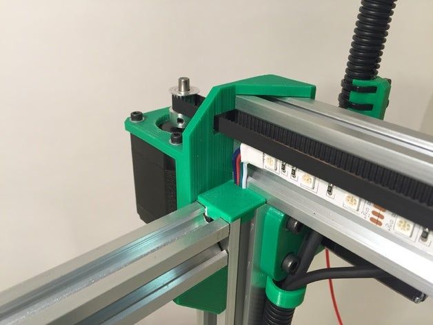
Tip: if your printer came with a belt tensioner in the form of a spring attached to the belt itself, remove it. Due to the flexibility of this tensioner, printing defects will occur, such as protruding corners on the model. It is better to adjust the belt without using this tensioner.
Belt tensioner
Current motors
As we know from the school physics course, the power of the engine depends on the voltage and current strength. Since the voltage on all printer electronics is the same everywhere, the only thing that can be changed is the current on the motor. More precisely, it should be said the maximum current that the driver will supply to the motors. To change this limit, you need to climb inside the case and find the printer board. On it you will see the printer driver. We are interested in a small potentiometer on the driver itself (in the picture below it is indicated as a tuning resistor).
Example of potentiometer location on driver
For adjustment, you will need a voltmeter and a small Phillips or flathead screwdriver. Before proceeding further, it is necessary to calculate the maximum current supplied to the motors. Different formulas are used for different drivers, the most popular ones will be listed in the table below:
| Driver name | Formula | Explanations |
| A4988 | Vref = Imax * 1. | To understand which formula to use, you need to find a resistor with the signature R100 or R050 on the driver. They are located next to the driver chip. |
| DRV8825 | Vref = Imax / 2 | |
| LV8729 | Vref = Imax / 2 | |
| TMC2208 TMC2100 TMC2130 | Vref = Imax * 1.41 | One formula for all drivers |
 25 for R100
 The value of the maximum current (Imax) depends on the motor controlled by the driver. This can be found in the engine specification or on the sticker on it. The following are the currents for the most popular motor models:
17HS4401 - current 1.7 A
17HS8401 - current 1.8 A
17HS4402 - current 1.3 A
Substituting the value into the formula, we get the Vref value for the maximum current supplied to the motor.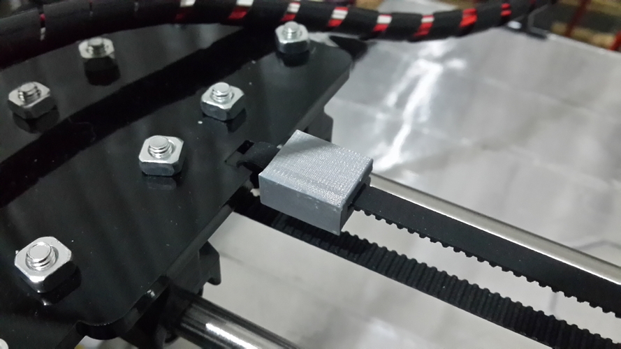 But at this value, the engine will get very hot, so the resulting Vref value must be multiplied by 0.7. For example, for a motor with a maximum current of 1.5 A and a TMC 2208 driver:
Vref=1.5*1.41*0.7=1.48V
Now the resulting value can be used when configuring on the printer itself. To do this, disconnect the wires going to the motors, turn on the printer and place one voltmeter probe in the center of the trimmer, and the second probe to the negative terminal on the power supply (you can also use the negative terminal on the printer board and the contact on the driver, labeled as GND). You will see some value on the voltmeter screen. Turn the trimmer clockwise to decrease the Vref value and counterclockwise to increase it.
Attention: you should not specify a Vref value higher than the maximum calculated for your engine! Otherwise, the engine will soon break down!
Once you have adjusted the value on the drivers, you can turn off the power to the printer, connect the motor wires, and put the case back together.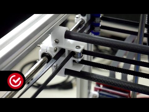 This completes the driver setup.
Motor steps
When setting up motor steps, you will need a ruler. For convenience, you can use the program Repetier-Host. The adjustment for each of the three axes occurs according to the same algorithm:
-
Set the caret to zero coordinates (Autohome or G28)
-
Move the carriage some distance
-
We measure how far the carriage has traveled
-
We calculate the correct number of steps per millimeter using the formula:
True steps per millimeter = current steps per millimeter * reported distance / distance traveled
For example, if the printer was set to 100 steps/mm, we tell the printer to move 80mm and the printer travels 87.5mm. Then the correct steps per millimeter would be 100 * 80 / 87.5 = 91.42 steps/mm. For the convenience of measurements, you can fix a ruler on the table, and a thin object, such as a needle or pin, on the carriage. Then it will be possible to accurately measure the distance traveled. The extruder uses a partially different algorithm to measure distance:
-
Inserting plastic into the extruder
-
Cut it right at the outlet
-
We give the printer a command to stretch the plastic a certain distance (at least 100 millimeters)
-
Cutting plastic again
-
We measure the length of the resulting piece of plastic
-
We use the formula from the previous algorithm
Next, the settings data must be inserted into the firmware in the line:
#define DEFAULT_AXIS_STEPS_PER_UNIT {X,Y,Z,E0}
X,Y,Z and E0 should be replaced by the steps per millimeter for each of the axes, respectively. Otherwise, you need to insert this line into the initial GCODE:
M92 Ennn Xnnn Ynnn Znnn
Instead of nnn in each of the parameters, you must substitute the steps per millimeter for each axis.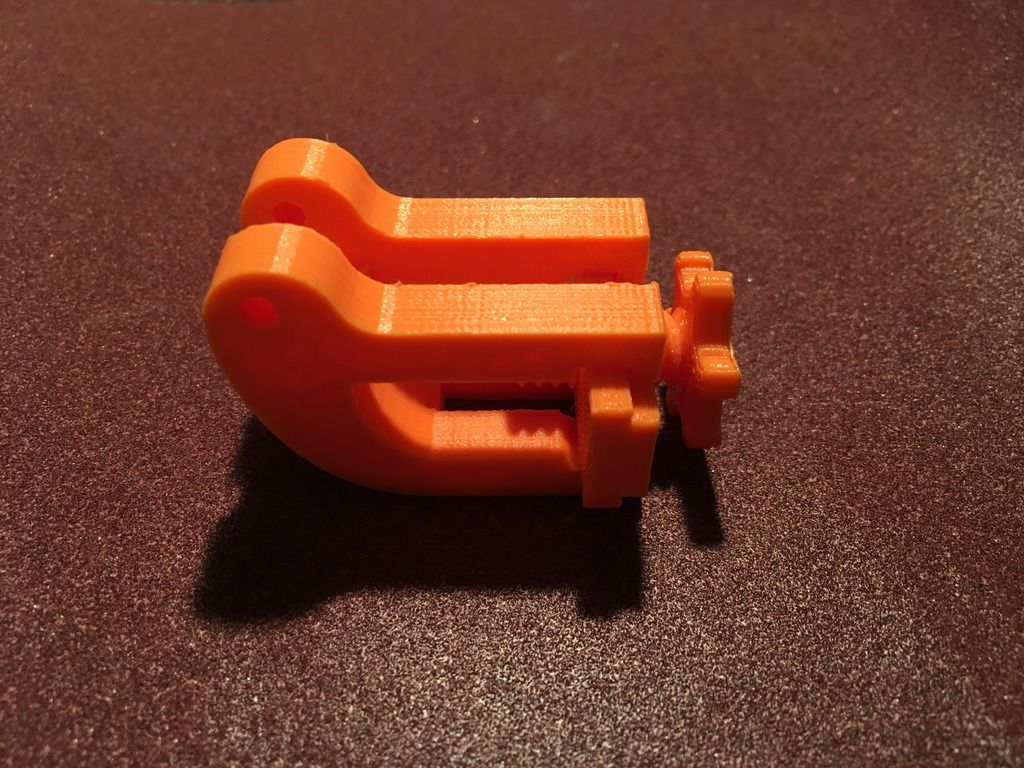 If you want to adjust the steps only for not all axes, then you can remove unnecessary parameters.
Acceleration
This parameter is responsible for the rate of change of speed. That is, how fast the printer will change its speed. This affects the nature of the movement of the hot end relative to the table. If the acceleration is too small, then the printer will print slowly, if it is too large, then the outer surface of the model will have visual defects: fading waves will be visible near each of the corners, as in the picture below.
To set up acceleration, you need to follow simple steps:
-
Cut a model of a standard test cube with a wall thickness equal to one nozzle diameter, without filling and top layers, bottom 2-3 layers;
-
Open GCODE file in notepad;
-
Find the G28 command at the very beginning and insert the line data after it:
M201 X5000 Y5000
M204 P500 T500
-
Save the changes, print the model according to the received GCODE and note at what parameters P and T it was printed;
-
Open the same GCODE file and change the P and T values on the second line, adding 500 to each;
-
Repeat steps 4-5 at least 3 times;
As a result, you will get several test cubes, some of which will show waves at the corners. Choose the cube that is printed with the highest P and T parameters, but that no waves can be seen on it. The number in parameter P will be the desired acceleration value. To save this value, you need to find 2 lines in the firmware:
#define DEFAULT_MAX_ACCELERATION {X,Y,Z,E0}
#define DEFAULT_ACCELERATION {nnn}
Instead of X and Y, you should put an acceleration twice as high as found earlier. And instead of nnn, you need to put the acceleration value found earlier. Otherwise, you need to insert a line in the initial GCODE:
M204 Pnnn Tnnn
In the parameters P and T, you need to put the value of the found acceleration. After that, the acceleration setting can be considered complete.
Jerk
A jerk indicates the speed with which to start accelerating. It affects the model in a similar way as acceleration: it creates ripples around the corners of the model. But it also increases the protrusion of the corners if the jerk is too small. The jerk setting is also similar to the acceleration setting:
-
Cut a model of a standard test cube with a wall thickness equal to one nozzle diameter, without filling and top layers, bottom 2-3 layers.
-
Open GCODE file in notepad
-
Find the G28 command at the very beginning and insert the line data after it:
M205 X5 Y5
-
Save the changes, print the model according to the received GCODE and note at what X and Y parameters it was printed
-
Open the same GCODE file and change the X and Y values on the second line, adding 2 to each
-
Repeat steps 4-5 at least 3 times
As a result, you will get several cubes. Find a non-rippled cube printed at the highest X and Y settings. This will be the jerk value for your printer. To save them, you need to find the line in the firmware:
#define DEFAULT_XJERKnnn
#define DEFAULT_YJERKnnn
It is necessary to substitute the jerk values for the X and Y axes, respectively. Otherwise, you need to substitute the command in the starting GCODE:
M205
Instead of nnn, you need to substitute the jerk value found earlier. This completes the jerk setting.
Speed
In fact, there are many different speed parameters, the values \u200b\u200bof which vary greatly. Let's take a look at the main ones:
This parameter is responsible for moving the nozzle without extruding plastic. The value is in the range from 80 to 120 mm/s. Limited only by the maximum speed at which the motors can rotate. Does not affect the model
This speed is important because it indirectly affects the adhesion of the model to the table. Usually lies between 15 and 30 mm/s
-Print speed of inner walls
Usually set to about 60 mm/s, it only affects the strength of the model. Depends on the maximum amount of plastic that the extruder can push through the nozzle
-Speed of printing outer walls
Usually about half the printing speed of the inner walls (30 mm / s).