Hiwin linear rail 3d printer
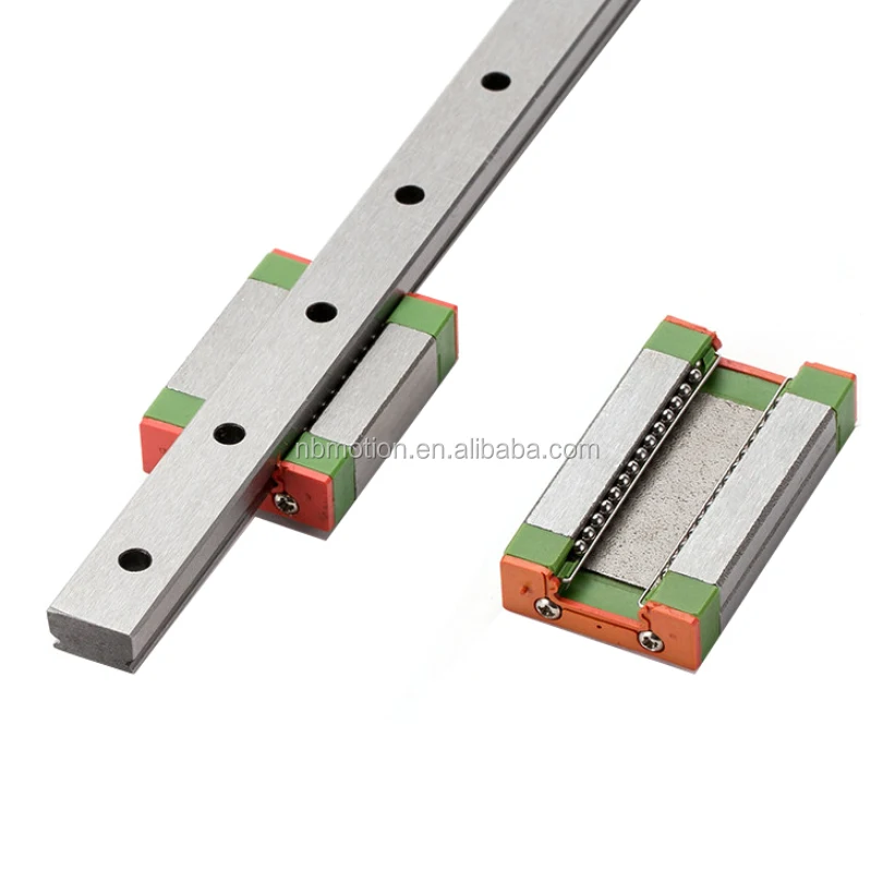
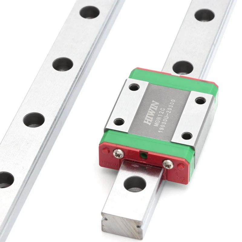
HIWIN MGNR12R Linear slider rail ( 40 cm ) | 3D printing experts
Overview Description Content Documentation Specifications
- High quality rail
- Width: 12 mm
- Length: 400 mm
- Material: Stainless steel
Stock - NL: 9
$ 92.50 excl VAT In stock
Only 9 left, order now!
Others also bought:
HIWIN
HIWIN MGN12C Slider carriage
$ 35.50
HIWIN
HIWIN MGN12H Slider carriage
Product description
High quality slider rail by HIWIN for high precision, smooth movements. Especially great for delta 3D printers. The rail comes with caps to avoid build up of dust in the mounting holes. Sliders sold separately.
HIWIN's stainless steel linear rails and sliders are machined to tight tolerances, providing a low friction slide with negligible 3-axis play over a lengthy lifetime. The HIWIN linear guideway of the MGN series is based on proven HIWIN technology. The Gothic arch contact design absorbs loads in all directions and is particularly rigid and precise. Given its compact and lightweight design, it is particularly suited to use
in small devices.
Design of the MGN series
- 2-row recirculation ball bearing guide
- Gothic arch contact design
- Stainless steel block and balls
- Rails made from standard or stainless steel
- Compact and lightweight design
- Balls are secured in the block by retaining wire
- Grease nipple available for MGN15
- End seal
- Interchangeable models are available in defined accuracy classes
Documentation
CAD Drawing Product catelog Assembly Instructions
What's in the box?
This is a kit of the following items.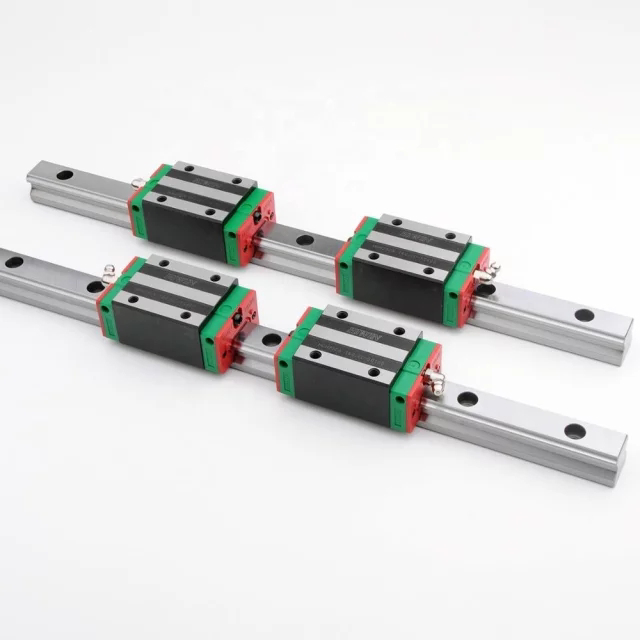
| 1x | HIWIN MGNR12R Linear slider rail ( 40 cm ) | |
| 1x | HWNMGN12 Caps ( 16 pieces ) |
Specifications
| General properties | |
|---|---|
| sku | HWNMGNR12-R400 HMC |
| gtin | 8719345012181 |
| mpn | MGNR12-R400 HMC |
| Material | Stainless steel |
| Dimensions | |
| Product Dimensions | 400x12x8 mm |
| Mounting hole size | 3 mm |
Linear Guideways | HIWIN
Linear guideways provides linear motion by re-circulating rolling elements between a profiled rail and a bearing block.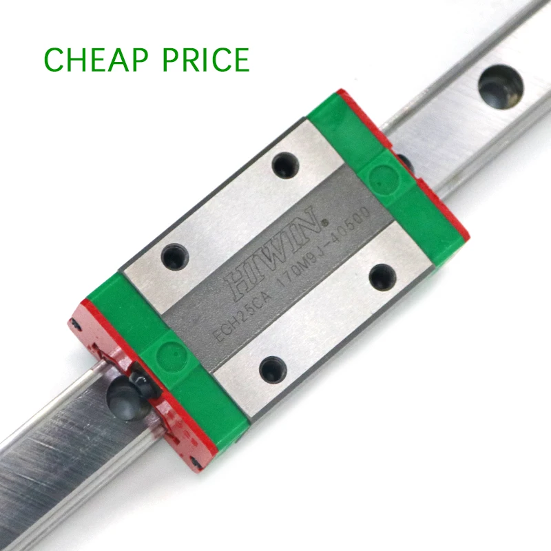 The coefficient of friction on a linear guideway is only 1/50 compared to a traditional slide and they are able to take loads in all directions. With these features, a linear guideway can achieve high precision and greatly enhanced moving accuracy. Hiwin Corporation offers multiple linear guideway series, each featuring different options for sizes, loading capabilities, accuracies, and more.
View E-Catalog
HG Series
Configure Series
Basic Dynamic Load Range: 11.38 kN - 208.36 kN
The HG series linear guideways are designed with load capacity and rigidity higher than other similar products with circular-arc groove and structure optimization. It features equal load ratings in the radial, reverse radial and lateral directions, and self-aligning to absorb installation-error. Thus, the HG series linear guideways can achieve a long life with high speed, high accuracy and smooth linear motion.
EG Series
Configure Series
Basic Dynamic Load Range: 5.
 35 kN - 33.35 kN
The EG series is a low profile, high load capacity, and high rigidity guideway block. It also features an equal load rating in all four directions and self-aligning capability to absorb installation-error, allowing for higher accuracies. Additionally, the lower assembly height and the shorter length make the EG series more suitable for high-speed, automation machines and applications where space is limited.
CG Series
Contact Us
Superior Moment Load Capacity
The CG series linear guideways have moment load capacities up to 50% higher than standard HG Assemblies. The O-Type (back-to-back) bearing configuration and an integrated recirculation unit optimize bearing circulation greatly improving moment load capacities and promoting smooth motion. An optional stainless steel cover strip increases dust protection and promotes smooth block transition.
RG Series
Configure Series
Basic Dynamic Load Range: 11.3 kN - 275.3 kN
The RG series features a roller as the rolling element instead of steel balls.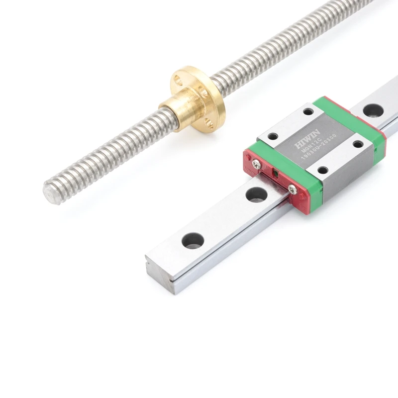 The RG series is designed with a 45-degree angle of contact. Elastic deformation of the linear contact surface, during loading, is greatly reduced thereby offering greater rigidity and higher load capacities in all 4 load directions. The RG series linear guideway offers high performance for high-precision manufacturing and can achieve a longer service life than traditional ball bearing linear guideways.
WE Series
Configure Series
Basic Dynamic Load Range: 5.23kN - 29.8 kN
The WE series features equal load ratings in the radial, reverse radial and the lateral direction with contact points at 45 degrees. This along with the wide rail, allows the guideway to be rated for high loads, moments and rigidity. By design, it has a self-aligning capability that can absorb most installation errors and can meet high accuracy standards. The ability to use a single rail and to have the low profile with a low center of gravity is ideal where space is limited and/or high moments are required.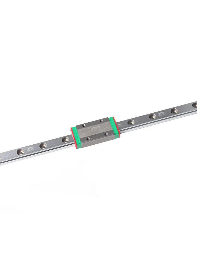
MG Series
Configure Series
Basic Dynamic Load Range: 0.68 kN - 8.93 kN
The MG series is a miniature linear guideway that comes in a compact size with a Gothic arch contact design that offers high stiffness and high rigidity against moment loads in all directions. The MG series also offers anti-corrosion protection which all material is in a special grade of stainless steel for compatibility in various working environments. The MG series is available in a narrow block type (MGN) and also with an enlarged width (MGW).
QH Series
Configure Series
Basic Dynamic Load Range: 13.88kN - 108.72 kN
The development of Hiwin’s QH linear guideway is based on a four-row circular-arc contact. The QH series linear guideway with SynchMotion™ Technology offers smooth movement, superior lubrication, quieter operation and longer running life. Therefore the QH linear guideway has broad industrial applicability in the high-tech industry where high speed, low noise, and reduced dust generation is required.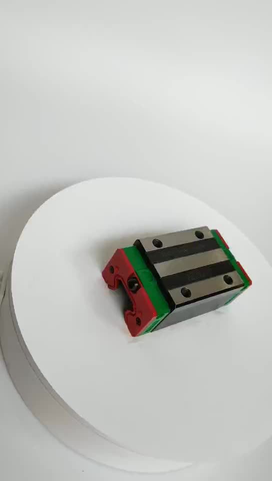 The QH series is interchangeable with the HG series.
QE Series
Configure Series
Basic Dynamic Load Range: 8.56 kN - 51.18 kN
The development of the Hiwin’s QE linear guideway is based on a four-row circular-arc contact. The QE series linear guideway with SynchMotion™ Technology offers smooth movement, superior lubrication, quieter operation and longer running life. Therefore the QE linear guideway has broad industrial applicability in the high-tech industry where high speed, low noise, and reduced dust generation is required. The QE series is interchangeable with the EG series.
QW Series
Configure Series
Basic Dynamic Load Range: 16 kN - 36.8 kN
The QW series linear guideway with SynchMotion™ Technology possesses all the advantages of the WE series, which features high moment rigidity and is suitable for single rail or space saving applications. With the SynchMotion™ technology it also provides quieter and smoother movement, superior lubrication, and longer service life.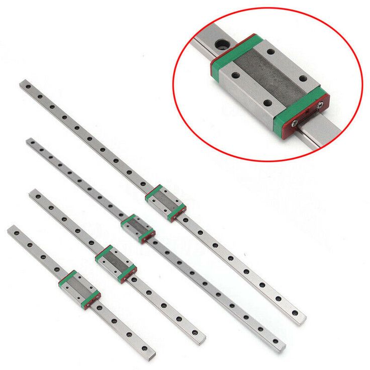 The QW series is interchangeable with the WE series.
QR Series
Configure Series
Basic Dynamic Load Range: 26.3 kN - 150.8 kN
HIWIN’s QR series offers super high rigidity and very high load capacities. The QR series with SynchMotion™ Technology offers low friction, smooth movement, quieter operation and longer running life. In industries where high accuracy, low noise and high rigidity are required, the QR series is the ideal guideway choice. The QR series is interchangeable with the RG series.
PG Series
Hiwin’s positioning guideway system integrates a linear guideway with a magnetic encoder. This solution offers the high stiffness and rigidity of a guideway while obtaining high precision from the magnetic encoder. The encoder is a non-contact measuring sensor and the magnetic strip is embedded to prevent possible damage caused from external materials, these features ensure a longer service life.
E2 Series
The E2 self-lubricating linear guideway has a lubricator installed between the end cap and end seal.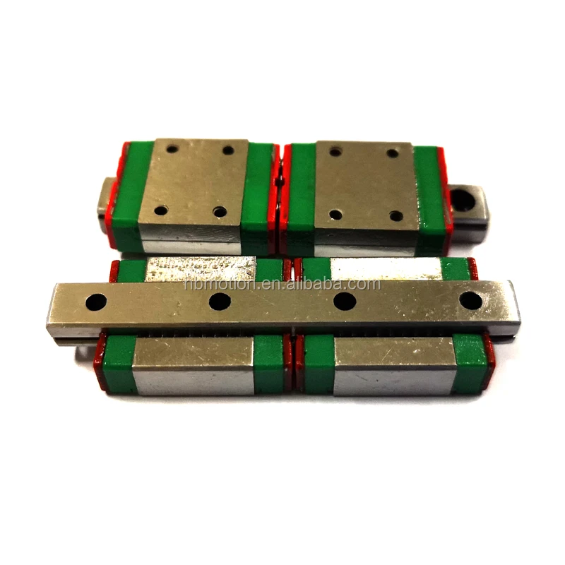 The block is also equipped with a replaceable/refillable oil cartridge with a removable cap for easy replenishment of oil. Lubrication flows from the oil cartridge to the lubricator and coats the grooves of the rail and raceway via capillary action. HIWIN’s E2 kit extends maintenance cycles and ensures long service life.
SE Series
The SE is a metallic end cap option for the linear guideway that increases temperature resistance. This option enables service temperatures up to 150°C and instance temperatures up to 200°C. For situations where a standard block is unable to operate due to the high working temperatures, the SE option is available for use.
Dust Proof Options
Dust proof attachments prevent material debris and dust particles from entering the block and causing damage to grooved surfaces. Dustproof options are recommended when a guideway is exposed to a high debris environment to ensure extended service life.
Reinforced Caps
The RC reinforced cap is constructed of an oil and abrasion resistant synthetic resin and elastic rubber O-ring.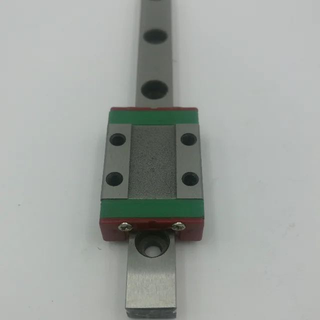 The cap provides high performance dust protection and is resistant to being unseated by vibration or shock.
Contact an Engineer Directly
View Our Online Catalog
Each 3D printer - on rails / Sudo Null IT News
I have long wanted to write an article about my positive experience of converting a 3D printer from linear rods to rails, it looks like the time has come.
In the course of this article I will tell you what and how I did, perhaps my experience will help someone put their workhorse on the rails.
▍ So let's start.
It seemed that not so long ago there was a dream to purchase a 3D printer, a dream come true, the ANET E16 printer was ordered back in 2019year from Uncle Liao's country.
Surprisingly, the printer arrived quickly enough and the box was almost without dents :) Naturally, the printer was assembled on the same evening and test prints were delivered: cubes, boxes, turrets.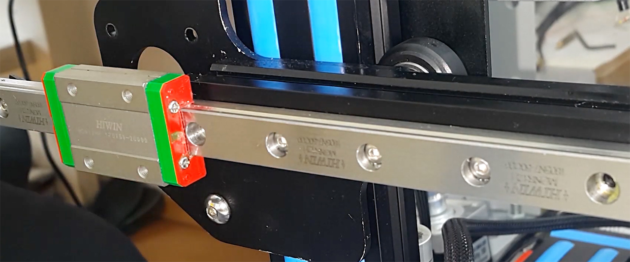 Traveled until late at night. The optimal settings were determined, adjusted, the table was leveled. Uhhh, when I remember, I shudder. It took about 2 weeks to set up the printer to achieve an acceptable print quality, but I had to learn to work with this miracle machine on the go, each time solving several tasks at once and not always sequentially. When the experiments led to good results, it pleased, so there is room to grow.
After 2 months of operation, in almost daily printing mode, I began to notice that when the table moved forward and backward (Y axis), as described, steel rods with a diameter of 8 mm (in fact, it turned out to be nickel-plated low-grade steel rods) and LM8UU linear bearings - they creak and the table wobbles, as if riding on potholes. Two rods plus 4 bearings, at first I looked if they were dry - grease was present. It turned out to be a load on the table and, accordingly, on the guide rods and bearings.
Along the guides, paths were gradually drawn from the pulled up material of the rods.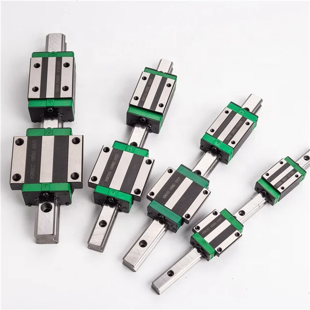
▍ Something needs to be done about this urgently!
Two elements make it difficult to achieve printing accuracy and smoothness of the table:
“Floating table” , you bring the table to “zeros” before starting the printer, and after starting work, the table leads in an unpredictable way to any of the cardinal directions, because. if the bearings work unevenly, then distortions, wedges are provided, a matter of time. 93 = 45,720 grams or approximately 46 kilograms. Even if we take into account that the bearings distribute the load into three unequal parts, roughly 46kg / 3, we get 15 kopecks per third of the length of the rods 50cm / 3 = 16.6 (and 6 in the period) centimeters in the ideal case. Taking into account the fact that the linearity of the rod along the line of movement is a key characteristic and ideally should not change at all, in my case the rods simply bend and this despite the fact that I never gave them the maximum load.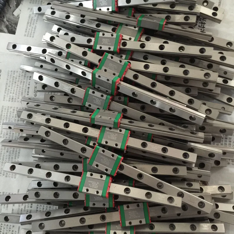 Realizing that the rods can’t hold such a weight, he left for a couple of days to read books, google and re-read dozens of forums in order to find out how people live with this and enjoy life by directly moving the 3d printer table?
As shown by the search and the results of reading books and forums, everything was invented before us.
▍ There is a way out! Rails are our everything!
In most options, rails with carriages are preferred, such as these MGN12H. In my case, the carriages were ideal in size and height, because. on the tips of the rails, you still have to install a regular limit microswitch.
The internal arrangement is shown below.
The rails themselves, carriages and bearings are made of durable steel. I ordered in China, from a seller with good reviews. Branded rails and carriages from HiWin cost like a small plane, but they give a guarantee on their rails and carriages.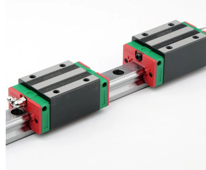
Let's estimate the "load capacity" of rails and carriages:
- Load capacity stat. 5.88 kN
- Load capacity dyn. 3.72 kN
kN - kiloNewton, kiloNewton Karl !, this is not a mistake, in statics it turns out that a rail with a carriage can withstand a mass in kg: 5.88 * 1000 / 10 \u003d 588 kg will withstand and will not hesitate and will not sell through. I counted twice, suddenly a mistake, I can’t even believe it. At a rail length of 500 mm, under our table, the rails with carriages do not even move, and before the deflection, the margin of safety is simply huge. I can’t imagine that you can ride on such little girls, just midgets on steroids.
The advantage of rails and carriages is described very simply, they are made with very high precision, the play is so small that when you move the carriage along the rail it seems that it does not roll, but flows along the rail. The move is so smooth that you wonder how so many ball bearings work smoothly.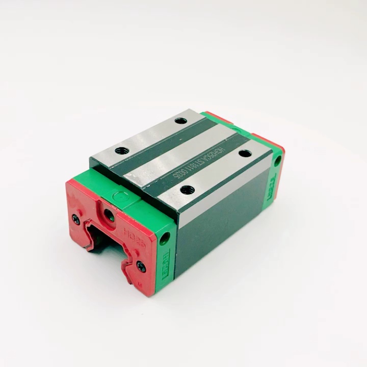 Whoever came up with this design is a genius.
I will have to work with exact dimensions and I will need a working printer to print new parts, I decided to model all the parts first in a 3D editor and not in vain, because fitting in hardware takes much longer than in a 3D editor.
I drew all the important elements: new tips are of a universal type, you can put them in any place, including under the end mic.
a substrate between the carriage and the table frame - it is very convenient to set up the table after assembling the entire structure.
As a result, after modeling, it turned out to be a fairly reliable, durable and simple design.
I printed for the last time, with a scratch, all the necessary details. He removed the tips, rods with bearings. I installed all the details, connected everything together with screws, that's what happened.
I installed the spring-loaded base of the table in its regular place, inserted the screws into the attachment points of the tips and tightened them according to their native fasteners.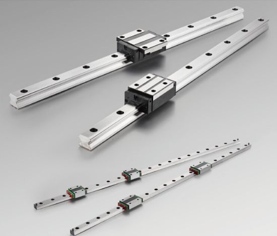 This is where the surprise awaited me. The table reached the middle and didn’t want to go further, as if resting on something, the answer came from the manual along the rails ... tolerance for parallelism ...
We are interested in the average accuracy - column H, for a length of 500 mm, Parallelism can deviate by 131 microns, no more. With a micrometer you will not jump, especially in motion.
It was decided to let this dynamic system level itself and self-adjust.
As time has shown, the decision was correct. Having loosened all the screws securing the tips, after 2-3 printing of test tasks, the rails stood up as they should. The carriage with the table rolled to its full length without jamming or stopping. Then the screws were tightened.
I am very pleased with my technical solution. The labor costs and time, not as big as many people think, that I invested in the design of the printer paid off completely, I have been printing since January 2020 and to this day everything works perfectly.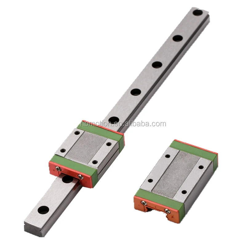 And every time, watching how the printer works, I rejoice like an elephant :)
▍ Finally reached the next
- Print quality improved.
- Printing accuracy has become at the level of 0.01-0.03 mm.
- No need to set up and calibrate the table every time, does not lead it, stands dead.
- The print speed has increased while maintaining the quality.
- Quiet operation of carriages on rails, the printer is almost inaudible during operation.
I am attaching a video of the end result.
For anyone who wants to repeat this path, here is a link to ThingiverseIf you have any questions, I will always answer.
Debunking the myths - shafts and rails.
Technical
Follow author
Follow
Don't want
45
Hi all! In the course of the discussion, it turned out that some seemingly obvious things may turn out to be completely non-obvious.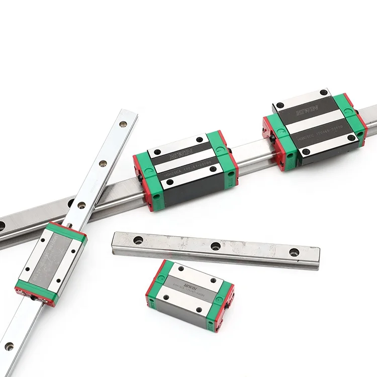 I decided to write short articles about some of them.
So, the first myth about linear guides is 'good shafts can be as good as rails'. Unfortunately, no, they can't, and here's why. To begin with, a small quote from wiki.purelogic.ru
POLISHED GUIDE SHAFTS
The most common and budget type of guides. High availability, easy handling and installation. Polished shafts are made of high-alloy steels, usually structural bearing steels, and undergo surface induction hardening followed by grinding. Shafts are factory induction hardened for long life and less wear on the shaft. The ground shafts have a perfect surface and provide movement with very little friction. The shafts are attached only at 2 points at the ends and therefore their installation is not particularly difficult. However, many unscrupulous manufacturers often make shafts from cheap and soft grades of high carbon steel, taking advantage of the fact that the buyer does not always have the means to check the type of material and its hardness.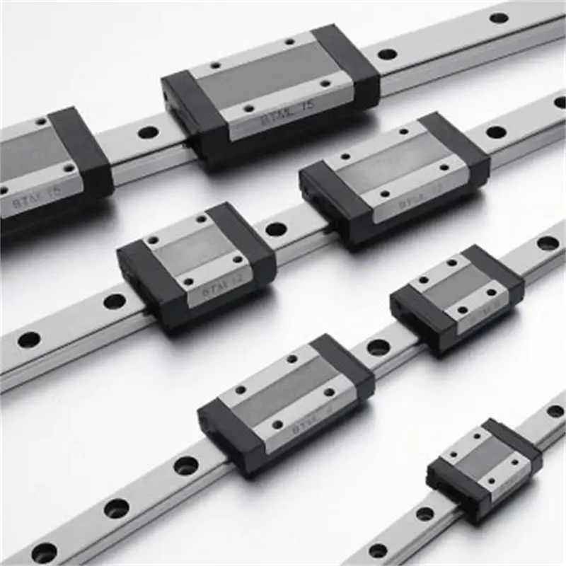 Disadvantages of polished shafts include:
- No attachment to bed.
The shaft is attached at two points at the ends - this facilitates the installation of the guides, however, the guides are installed independently of the working surface of the steel. At that time, in portal machines, it is highly desirable to put guides in a rigid connection with the table (such a connection reduces processing errors if the desktop has undergone a warp, “driven by a screw” - the guides, repeating the bends of the table, level out part of the error).
- Long sag.
In practice, due to sagging, shafts are used no longer than 1 meter. In addition, the ratio of the shaft diameter to its length is important - to obtain acceptable results, its value should be at least 0.05, preferably within 0.06-0.1. More accurate data can be obtained by simulating the load on the shaft in CAD packages.
Linear bushings.
Linear rolling bearings have relatively large backlash compared to rail guide carriages and lower load characteristics.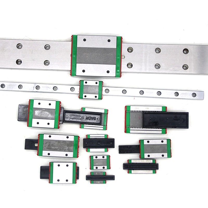 In addition, to protect against the rotation of the carriage, it is necessary to use at least two guide shafts per axis. Disadvantages of linear rolling bearings:
- Low load capacity
Consequence of the previous point and the design of linear bearings.
- Short life.
Each ball of a linear bearing touches the shaft at one point, which generates very high pressure. Over time, the balls can roll a groove on the shaft, after which the shaft must be replaced.
- Backlash.
Low cost linear bearings by many manufacturers are often made with a very significant backlash.
- Fairly sensitive to dust and chips on the shaft. So,
So, the main conclusions about the shafts - the main drawback of the shafts is that they are attached to the frame only at two points at the ends. Therefore, the shafts do not perceive transverse loads well and, roughly speaking, easily bend and vibrate under the influence of static and dynamic forces arising in the kinematics of the printer.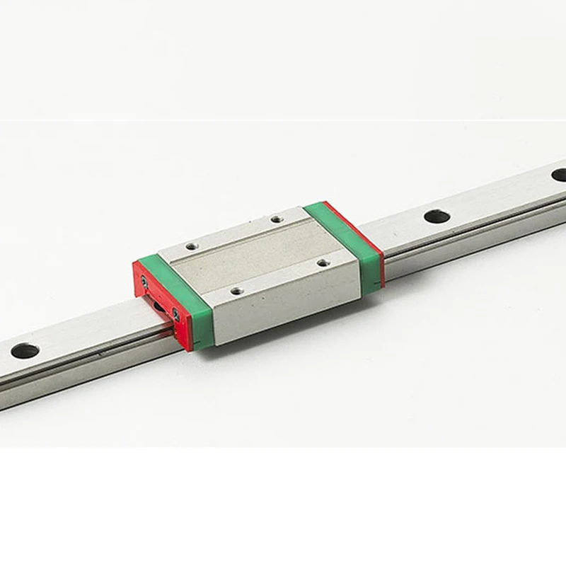 With an increase in print speed, and hence with an increase in dynamic loads, this leads to inaccurate positioning of the print head, and hence to a deterioration in print quality. First of all, this is observed in the form of lubrication of the sharp corners of the model.
In order to confirm this theory, I can propose a simple experiment using a digital caliper:
When slightly pressed with a finger, the shaft bends by hundredths and even tenths of a millimeter. Such deformations are comparable to the layer thickness during printing, which means that they significantly affect the geometry of the printed model. How to deal with this trouble? Very simply, there is an alternative for this - BALL PROFILE RAIL GUIDES, or, more simply, RAILS. Again a quote from wiki.purelogic.ru:
Profile rail guides are used where high precision is required. As well as cylindrical, profile rails are attached directly to the machine bed. Special raceways are made in the profile rails, as a result, the load on the carriage is distributed evenly over the working surface of the raceways - the contact profile of the ball-rail is no longer a point, but an arc.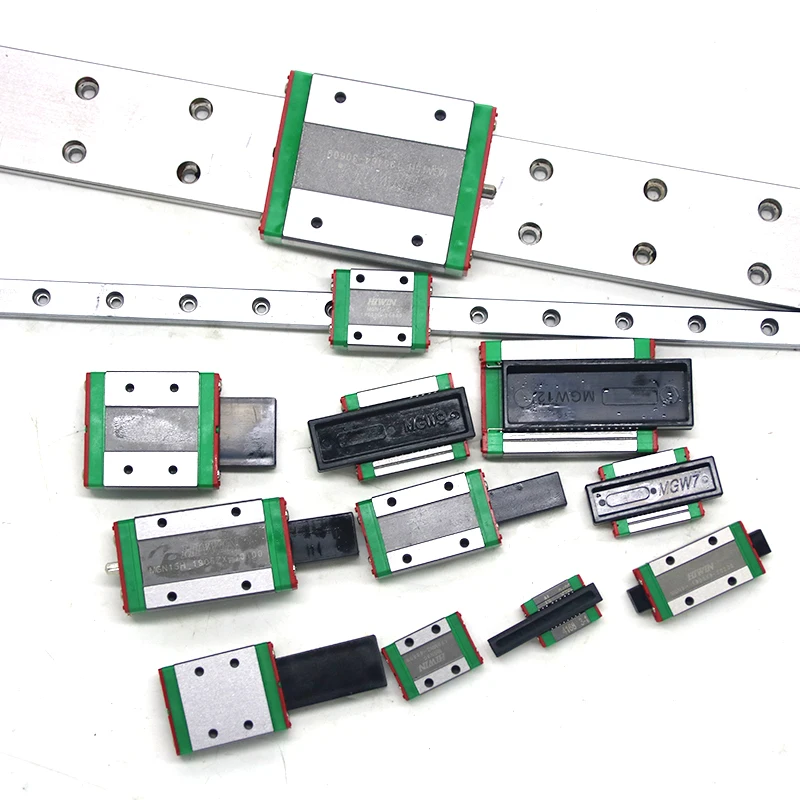 Profile rails are characterized by high precision and straightness, high load capacity, high wear resistance, low backlash or no backlash. The disadvantage of profile guides is the high requirements for roughness and straightness of the attachment point, as well as the complexity of installation. As a rule, rails and carriages are produced in several versions - with preload and load capacity of varying degrees. Hiwin and THK rail guides are classic examples. Profile rails are difficult and expensive to manufacture, so there are fewer rail manufacturers than shaft manufacturers, and they (usually) value their reputation, the quality of profile rails is much more stable.
Intermediate leads - the main advantage of the rails is that they are attached to the frame at several points along their entire length, which means they do not bend under loads, do not vibrate, and even in the middle along the length they transfer loads to the frame. And the rest of the characteristics of the rails consist of some advantages (we will not go into depth).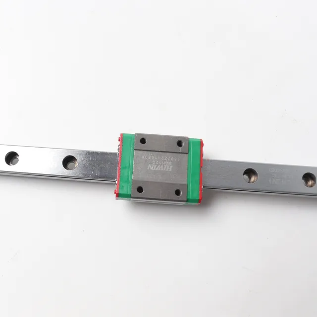 The only drawback is the high price. In addition, 'Khivan' rails start from size 12, which is obviously redundant and heavy for a 3D printer.
But in this case, our Chinese friends come to our aid. They have mastered the production of relatively inexpensive and good in terms of their characteristics sets of rails MGN9 + single-row ball carriages MGN9C and MGN9H. Carriages with index H are longer and are most suitable for printer construction. Brief characteristics:
The table shows that the 9th standard size is ideal for our tasks. Roughly speaking, one such rail can easily replace two 12-shafts, and even has advantages in terms of its load characteristics. In addition, the rails make the printer kinematics more compact and significantly reduce the weight of the printer's moving parts. All this in turn allows you to significantly increase the speed of printing without compromising quality. In my opinion, increasing the print speed is one of the main tasks in improving the FDM technology.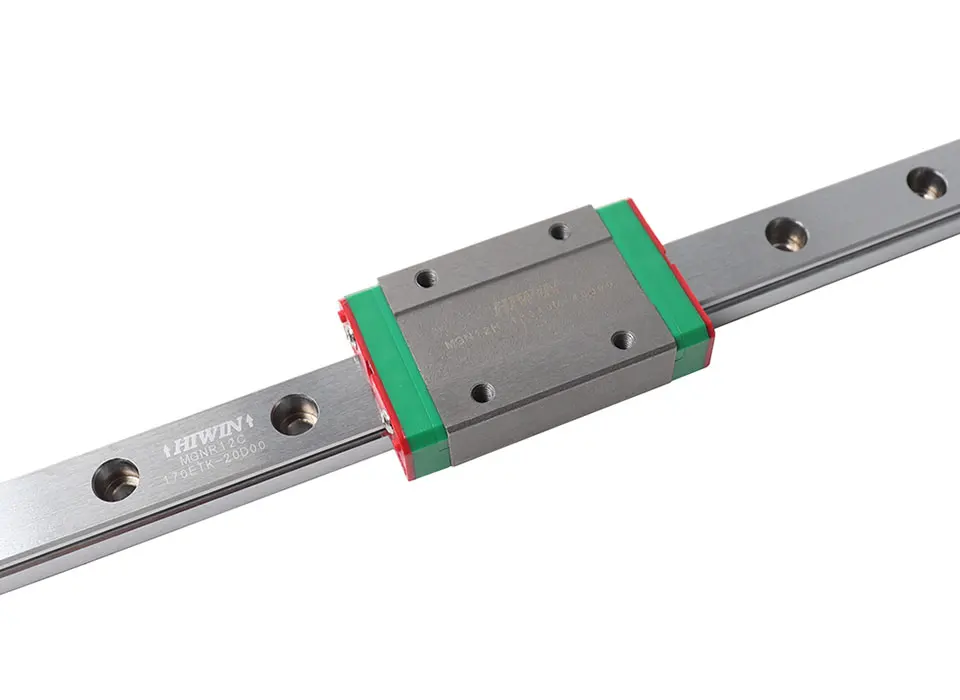 And it will be very good if we can print 2-3 times faster with the help of rails.
Follow author
Follow
Don't want
45
More interesting articles
Artego
Loading
11/09/2022
827
eight
Subscribe to the author
Subscribe
Don't want
In general, on the second day after printing, I could not stand the test deer on this miracle, because this product scree...
Read more
four
Follow author
Follow
Don't want
Alekmaker G.T. was purchased in 2017, and after 3 years of good work, I have accumulated...
Read more
243
Subscribe to the author
Subscribe
Don't want
Good afternoon.