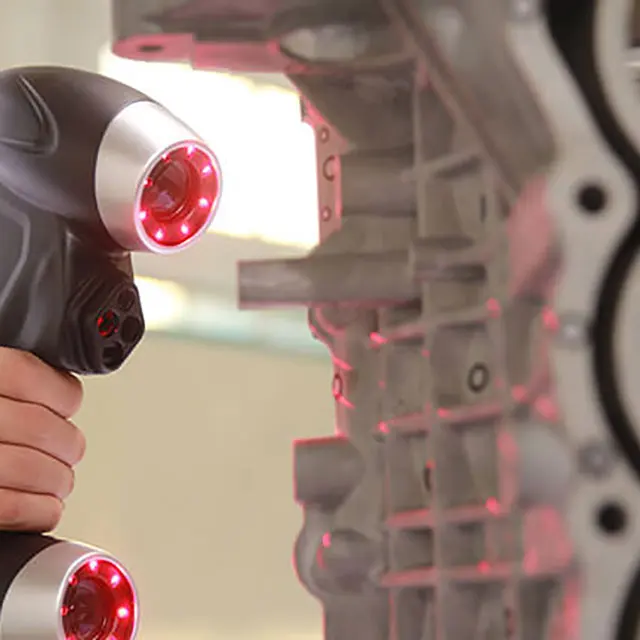
Handheld 3d scanner reverse engineering
3D Scanners for Reverse Engineering
Hi everyone! This is Top 3D Shop, and in the following review, we will talk about reverse engineering, the considerations when choosing 3D equipment for it, and related case studies.
Read on to learn more.
What is reverse engineering?
Source: 3daeroscan.com
Reverse engineering, also known as back engineering, is the process of creating a project of parts or products with no drawings or documentation. By creating a digital CAD model using 3D scanning, these parts can be modified and optimized to extend their lifetime or add new functions. This method is used in many industries, including the production of military equipment or spacecraft.
With the growing popularity of 3D printing, reverse engineering is gaining ever-increasing attention. This is due to the fact that the reproduction of an object or design using digital modeling and 3D printing is more accessible to ordinary users than other production processes.
The ICON company uses a variety of 3D scanners to reverse engineer vintage car parts.
Source: 3dreveng.com
The process of reverse engineering involves three tasks: obtaining a sufficiently accurate digital impression of a part, converting the resulting image into a solid 3D model in specialized software, and subsequent digital processing of the model to eliminate artifacts, convert the format, and make some modifications so that the model design is suitable for the product launch.
Therefore, it is necessary to choose the right 3D scanner to obtain the primary data that best suits the existing task. For example, it is completely pointless to scan a piece of jewelry with a time-of-flight scanner for large objects, and vice versa: the very high accuracy of a desktop or handheld scanner is redundant when scanning, for instance, a sea vessel.
NeoMetrix Technologies uses the Creaform HandySCAN 700 3D scanner for reverse engineering and metrological control of various objects.
Stages of reverse engineering
Source: 3dcaptura.cz
1. Prepare the object for scanning, apply markers if necessary. Note that glossy surfaces impede the work of 3D scanners, and reflective or transparent ones are nearly impossible to scan without a matte finish, so spray a temporary matte powder on the object to improve scanning accuracy.
2. Use a 3D scanner to capture important areas of the part. You may need to orient and rescan your object several times if it has holes or deep grooves.
3. Adjust and optimize the resulting polygonal mesh. Some scanners create very large files, making it difficult to post-process and print an object. Remove artifacts, check the surface stitch.
4. Import the mesh into CAD software equipped with reverse engineering tools.
5. Convert polygons to solids.
6. If necessary, add new objects to the resulting 3D model or delete unnecessary ones.
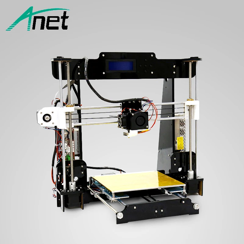
7. Use 3D printers or CNC machines to produce a new part according to the created model.
Reverse engineering of automotive parts with a Creaform 3D scanner using the VXmodel and Autodesk Inventor software
Case studies
Reverse engineering of an impeller
Source: 3d-scantech.com
An equipment manufacturer needed to optimize the production of impellers and eliminate manufacturing variances. It proved impossible to obtain accurate data of a part with holes, dead angles, and geometrically complex surfaces by traditional means. The impeller has narrow gaps between the vanes, which prevents measurement with a probe, so it was decided to employ 3D laser scanning and process the results using reverse engineering methods for comparison with the original digital model.
Source: 3d-scantech.com
3D scanning was performed by means of the ScanTech PRINCE high-precision 3D scanner with red and blue laser scanning modes. The device has a resolution of 0.020 mm and can quickly switch between modes. It is capable of scanning deep holes with a single red laser line and capturing the smallest details. In addition, the scanner is insensitive to ambient light.
Source: 3d-scantech.com
A full detailed model of the impeller housing with vanes was obtained using the 3D scanner.
Source: 3d-scantech.com
A complete digital model was created for analysis.
Creating an audio speaker cart using reverse engineering
Source: shining3d.com
To participate in a sports and dance event called Colorguard, a captain had to do something for her team. She decided to create a cart for a heavy speaker that girls use to play music during training and performance.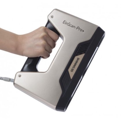 The speaker was to be easily removed from the cart if necessary. Besides, one of its handles needed restoration.
The speaker has three identical handles attached with screws. To replace the broken handle with a new one, the EinScan-SP was used to scan one of the remaining handles. Since the handle was very dark, it was dusted with a thin layer of baby powder so that the scanner could correctly recognize the surface. The EinScan-SP has the function of automatically stitching images when the object is rotated on the turntable and in different positions of the object. The program selects certain points from several scans and connects them. This allows users to scan not only the sides but also the top and bottom of the object.
Source: shining3d.com
To clean up the resulting image from artifacts and eliminate any damage on the handle, the Deform: Smooth tool in the free Autodesk Meshmixer utility was used. Using the Edit: Erase and Fill tools, the existing manufacturer's logo was removed, with the event logo added.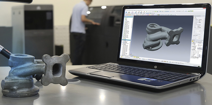 Meshmixer was also used to make sure the screw holes were cylindrical. Processing the resulting STL file in Meshlab simplified the model and reduced the file size from 26 to 2.4 Mb.
Source: shining3d.com
The handle was printed using the Afinia H+1 3D printer with a TPU extruder and NinjaTek's Cheetah flexible filament. For greater rigidity, 80% filling was used. The resulting handle turned out both durable and pleasant to touch.
Source: shining3d.com
After examination, it was decided to use the speaker mount holes as attachment points to the cart. Measurements with a caliper would have taken plenty of time, it was more efficient to use the Shining 3D EinScan Pro 2X Plus portable 3D scanner. Markers were applied for better surface capture.
Source: shining3d.com
Although the EinScan Pro 2X Plus comes with the Solid Edge software (a complete CAD package with reverse engineering capabilities), it was decided to use Autodesk Fusion 360 because the user was more comfortable with it.
Source: shining3d.com
The resulting 3D model was too large to be printed in one piece, so it was split into two parts. It was printed with black PLA.
Source: shining3d.com
The print path was optimized to increase the strength of the cylinder and walls.
Source: shining3d.com
The cart handle was made of acetone-welded ABS plastic, and a piece of chipboard was used to make the base plate.
Reverse engineering of stamping dies
Source: metrology.news
Gestamp is an international company engaged in the design, development, and hot stamping manufacture of metal automotive parts for major carmakers. In modern production, there occurs a situation when changes are made to a CAD-designed die directly in production. Manufacturers often forget to reflect such changes in the documentation/original model. As a result, when a die is replaced on account of wear or damage, engineers have to make undocumented changes anew, which leads to errors and an increase in flaws.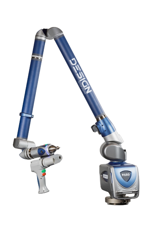
Source: metrology.news
This situation can be fixed with the use of reverse engineering. After a die is set and configured, it is scanned and all the changes are recorded in the digital model. The resulting file, which fully corresponds to the scanned surface including the smallest details, is used for reverse engineering of the die. Changes identified using this method are incorporated into the original 3D model of the die.
Source: metrology.news
Gestamp specialists work with the Creaform HandySCAN 3D scanners, appreciating their accuracy, convenience, and compatibility with reverse engineering software.
Footwear design using reverse engineering
Source: rangevision.com
RangeVision specialists investigated the possibility to speed up reverse engineering of objects with a large number of surfaces that change their curvature in accordance with mathematical laws. They used the sole of sports shoes as a test surface with such properties.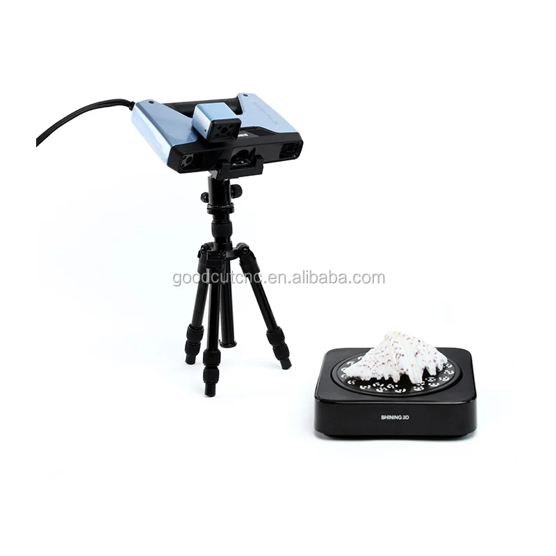
Source: rangevision.com
For this, they performed a 3D scan of the sole's geometry using the RangeVision Spectrum high-resolution 3D scanner (adjusted for object sizes from 30 cm to 1 m) and a rotary table. In 25 minutes, the device completed two groups of 8 scans, which were automatically linked into one model by the scanner software. Post-processing in the RangeVision ScanCenter program and obtaining a 3D model in .stl format took another 35 minutes.
Source: rangevision.com
Reverse engineering of the sole was carried out in Geomagic Studio using the NURBS method. First of all, artifacts and digital noise were removed, a coordinate system was created, unnecessary details were cut off, and the boundaries were smoothed.
Source: rangevision.com
After applying the NURBS method to the resulting surface, the final 3D model was created. Reverse engineering using NURBS took 4 hours. The entire task was completed within one working day.
Scanning of different objects, DE-Engineering
Source: rangevision.com
The DE-Engineering company fulfills orders on high-precision 3D digitizing and reverse engineering of various objects, from aircraft to jewelry. The founder Dmitry Epstein maintains a video blog on YouTube, in which he publishes the most interesting works. DE-Engineering uses the RangeVision PRO and Gom Atos 3D scanners.
Source: rangevision.com
3D scanning of large objects, such as the frame of a helicopter or an airplane, has some peculiarities: to save time, markers are glued with strips of masking tape, and scanning is carried out from several points to facilitate stitching of the model.
Source: rangevision.com
For the armoring of two Citroen Jumpy vehicles, DE-Engineering specialists performed 3D scanning of the body and created an accurate model, according to which the metal plates were manufactured. The high precision of reverse engineering made it possible to install the armor without any additional fit.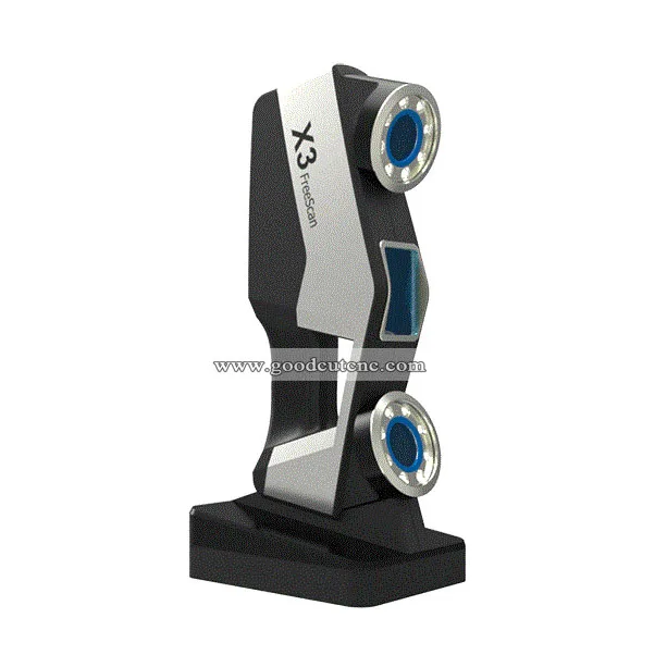 The whole process took seven days — two days for scanning and five days for processing.
Source: rangevision.com
DE-Engineering tries to use point cloud processing instead of polygons, which is more convenient from the point of view of model simplification. This allows maximizing the detail of an object in complex geometry areas and reducing it in simple ones. Processing is performed with the Catia software. Replaceable lenses are used to scan jewelry.
3D scanning in reverse engineering of a complex-shaped part, Top 3D Shop
A client contacted Top 3D Shop with a request to restore a broken plastic part of a complex shape.
The part was created by 3D scanning with the RangeVision Pro, reverse engineering, and 3D printing.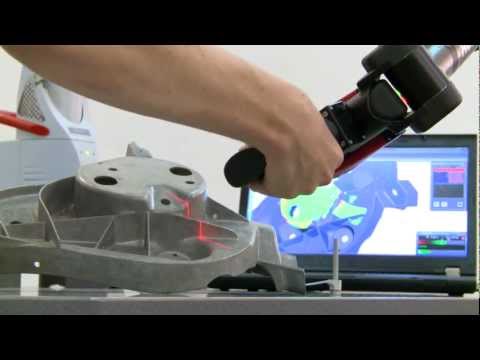
Step 1. The length of the part is about 30 cm, so it was impractical to use medium-precision handheld scanners and solutions for large objects. Desktop scanners with a multi-axis table were not suited either, because the object did not fit in length into the half-open scanner camera. Thus, stationary optical or high-precision handheld scanners seemed to be the only options.
Step 2. The object has a geometry of medium complexity. For good scanning of such parts, a scanner accuracy of 40–60+ microns is required.
In the images: solid models of the object with the restored integrity
Step 3. The higher the accuracy of a 3D scanner and the more features it has, the more expensive it is. The customer's budget did not allow the use of GOM, Solutionix, or Scantech scanners, so Top 3D Shop employed the RangeVision Pro, which scans such small objects with an accuracy of 40 microns. Based on the data obtained from 3D scanning, reverse engineering was performed, and the part was prepared for printing.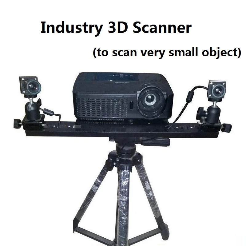
How to choose a 3D scanner for reverse engineering
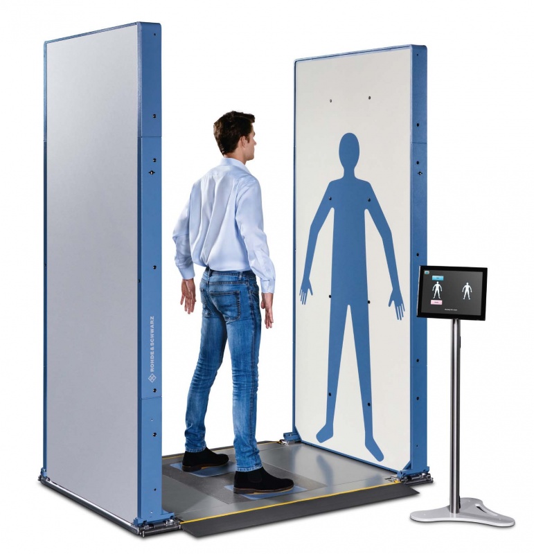
First of all, it is necessary to define the size of the scanned objects — this affects the choice of scanning technology and the type of scanner (desktop, handheld, or floor-standing):
- For objects larger than 10 m in any of the coordinate axes, 3D scanners with the usual laser triangulation or structured light technologies are not suitable. Scanning such objects even with a handheld scanner will take a lot of time, and the accuracy of data decreases. This problem is partially solved by photogrammetry. Therefore, for very large objects (airplanes, ships, buildings), it is most effective to use time-of-flight (ToF) scanners.
- For objects larger than 50 cm but less than 3 m, it is recommended to use handheld scanners — optical or laser ones.
- For objects from 10 to 50 cm, stationary desktop or portable floor-standing 3D scanners suit best (both optical and laser). Optical desktop and floor-standing scanners are more affordable than laser ones.
 Some handheld laser scanners can be used for tasks requiring high scanning speed.
 - Desktop high-precision optical scanners are best for small objects. Scanners of this type can be divided into two groups: dental and versatile.
Dental scanners feature immensely high precision, high resolution, and rotary tables with the ability to attach an occluder and impression stands.
Versatile scanners are usually equipped with a multi-axis rotary table, or the scanner itself is fixed on axes with several degrees of freedom. This design allows for autonomous scanning of most of the object's surface. These scanners have a good scanning depth to correctly capture grooves.
For objects with a size of 10–50 cm, laser handheld scanners are better suited if at least one of the following conditions is met:
- 3D scanning is planned to be used very often;
- the object to be scanned cannot be transported to the workshop; for example, it is a non-removable part of a massive mechanism, or transportation is impossible for other reasons;
- there is not enough room to place a stationary scanner;
- the surface of an object is difficult to scan with optics — it is black or highly reflective.

After defining the size of scanned objects, it is important to find out the required scanning accuracy and the measurement tolerance and see whether a metrological scanner is needed.
Reverse engineering of car parts at Jay Leno's Garage using the Faro Quantum ScanArm HD 3D laser scanner and the Stratasys Dimension 1200es 3D printer
Software for modeling and reverse engineering
Software for creating polygon models
Source: all3dp.com
To create point clouds and polygon models, it is usual to employ the proprietary software of a 3D scanner. Some 3D scanning and reverse engineering software products can also work directly with the most popular scanners.
Software for converting polygon models into solid ones
Geomagic Essentials
Source: einscan.com
Geomagic Essentials is a program that extracts all the necessary elements of a scanned part for direct use in a CAD package.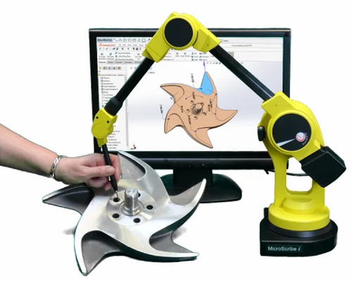 This software is designed to work with scans made by the Shining 3D EinScan Pro 2X (a joint product of 3D Systems and Shining 3D), which automatically processes and transfers the received data to the CAD environment. The application can be used both for metrological control and reverse engineering of parts and assemblies. The proprietary algorithms of mesh alignment and restoration, a wide range of options for fitting elements, the capability of creating cross sections, and high performance when working with large amounts of data can significantly reduce the work time of specialists.
Employing Geomagic Essentials to reverse engineer fan blades by user Gregory George
Geomagic Design X
Source: 3dsystems.com
Geomagic Design X is versatile professional reverse engineering software that combines traditional CAD functionality with 3D scan data processing.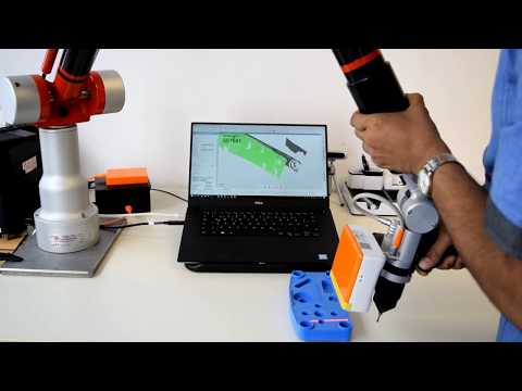 Design X allows creating functional, editable solid models compatible with CAD software. The proprietary algorithms for accurate surface fit to 3D scans, mesh editing, and point cloud processing enable the design of components that perfectly integrate with existing parts. The easy-to-use mesh repair tools provide fast hole filling, smoothing, optimization, and comparison with the original model.
Reverse engineering of a compressor at Artec 3D using 3D scanning and the Geomagic Design X software
Autodesk Meshmixer
Source: all3dp.com
Autodesk Meshmixer is completely free software popular with 3D printing professionals. Meshmixer is designed for working with polygonal meshes rather than for parametric modeling and has a large set of tools for this. The functions of automatic analysis and correction are very convenient for processing 3D scans. The program is also capable of preparing a model for 3D printing, including supports. Meshmixer is simple and easy to use, with many tutorials available online.
The first video by AutoDesk to demonstrate the capabilities of Meshmixer
Software for working with solid models
SolidWorks
Source: blog.trimech.com
SolidWorks is a 3D design and reverse engineering program. Apart from traditional CAD/CAM functions, the software includes specialized tools for designing sheet metal parts, welds, and dies. A huge library of components and parts, improved realistic rendering, the capability of design check and structure analysis make SolidWorks one of the most powerful 3D engineering software products available.
The first video from the series of SolidWorks software tutorials: reverse engineering and 3D scan processing
Solid Edge
Source: youtu. be
be
Solid Edge is an easy-to-learn toolset that covers all phases of product development: CAD design and rendering, modeling, reverse engineering, data management, and more. Siemens also provides training resources, access to the Solid Edge community, and ongoing software updates. If certain conditions are met, Solid Edge Premium can be used free of charge for one year.
Demonstration of the capabilities of Solid Edge 2021 from Siemens Software
Autodesk Fusion 360
Source: all3dp.com
The Autodesk Fusion 360 software and all of its modules are free for students, educators, hobbyists, and small businesses. The program is designed primarily for working with solid objects and is equipped with functional plug-ins.
Reverse engineering of a plastic housing at Dream3D using the HDI 3D scanner and the Autodesk Fusion 360 software
Legal issues of reverse engineering
Source: scantech.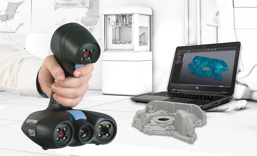 com
com
The dark side of reverse engineering is intellectual property forgery and theft. The growing availability of the technology can give an advantage to unscrupulous manufacturers when legislation lags behind modern requirements. This means that prototypes that took developers a lot of time and money can be counterfeited with impunity using 3D scanning and printing technologies.
The ease of copying product designs forces large companies to experiment with ways to protect their intellectual rights — for example, by creating product defects that appear only in unauthorized production, or by embedding authentication barcodes directly into manufactured products.
Full 3D scanning and reverse engineering of a car body using the Creaform Go!SCAN SPARK 3D scanner.
Conclusion
Source: ductim-x.com
The future of reverse engineering lies in even greater process automation.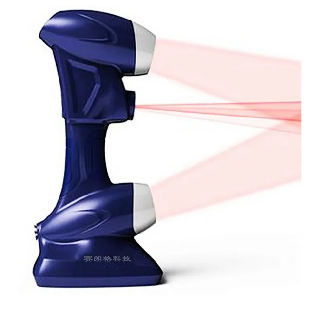 Manufacturers are increasingly employing the power of artificial intelligence and cloud technologies in scanning and post-processing to enable inexperienced clients to carry out their work autonomously. This can be useful for specialists in a variety of fields, from doctors scanning body parts to workers on construction sites. 3D scanners keep on penetrating the consumer market and may eventually become as commonplace as cameras on smartphones (some of them are already equipped with a ToF sensor).
3D scanners for reverse engineering — best Artec 3D scanning solutions
Applications
HD meshes for CAD workflows
Confidently and easily capture data from existing parts with the assurance of ultra-high precision and accuracy.
Rapid prototyping
With tools that seamlessly integrate into your existing workflow, you can quickly and easily prototype, test, and get insightful feedback on design solutions.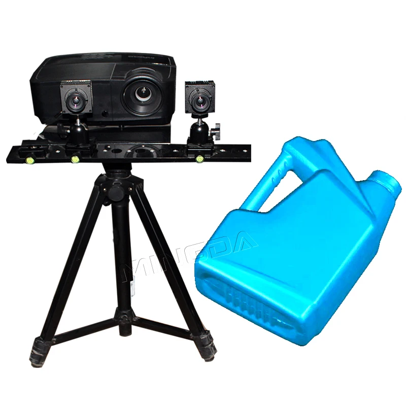
Retrofitting
Redesigning parts that are no longer in production has never been easier, with none of the errors, inconsistencies, and time demands that come with taking measurements manually.
Aftermarket parts production
With reliable 3D scan datasets, paired with Artec Studio’s versatility, you have the ability to develop high-quality aftermarket parts.
Additive manufacturing
You can take advantage of the flexibility that 3D printing brings to quickly actualize and test reverse-engineered designs.
A leading developer of high-performance chassis saves days of work by using Artec Eva, Artec Studio, and Geomagic Design X to engineer custom solutions for racing.
7x
reduction in time spent capturing and processing scans.
“Eva has been such a game-changer. Now I’ll take a bunch of parts and scan them in before lunch. By the end of the day, we’ve done all our analysis, everything is on schedule to create the final design.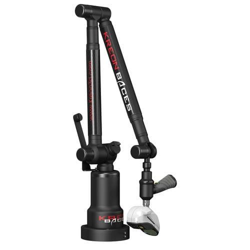 ”
”
Jason Heard, Co-founder, Tekk Consulting Inc.
Read full story
In the media
Royal Netherlands Navy 3D scans their ships using handheld Artec 3D scannersTHE VERGE
Classic Land Rover goes electric with the help of Artec LeoTop Speed
3D scanning ensures cameras will mount to helicoptersMake Parts Fast
User-friendly portable 3D scanner with an inbuilt touchscreen and intuitive UI for easy 3D scanning.
Learn more
Our bestselling 3D scanner. Fast, versatile, and accurate.
Learn more
A metrological structured-light 3D scanner, set apart with its ability to render complex geometry, sharp edges, and thin ribs in high precision.
Learn more
Powerful long-range laser 3D scanner with an inbuilt battery, for precise capture of large objects.
Learn more
Metrology-grade desktop 3D scanner for quality control, inspection, jewelry, medical/dental components, etc.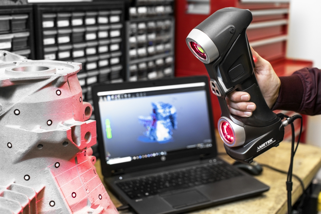
Learn more
Using Artec 3D scanning technology to keep Dutch Royal Navy ships seaworthy
“We are now able to work a lot faster and more accurately. Because we now have a complete 3D model, we have all the correct dimensions of every object. It results in a far more efficient way of working and it is faster, so we save a lot of money in these projects.”
Ben Jansen, CNC coordinator at the Netherlands Defense Ministry
Read full story
Reverse engineering huge machine parts in difficult locations with Artec Eva and Geomagic Design X
“Artec Eva was the suitable scanner for this job as the parts were very big and the accuracy required was in the range of Artec Eva’s accuracy. The scanning was pretty fast and easy considering that those were huge parts, around 3 meters…No other scanner can measure such big parts this accurately and fast.”
Ali Can Boysan, Teknodizayn Sales & Technical Support Manager
Read full story
Putting Claws on the Black Panther Lexus with Artec Eva at West Coast Customs
“It's a huge help that Eva is lightweight and comfortable to hold, which makes scanning actually fun to do … you don’t need to use it for long before you look over at the laptop and realize that you’ve scanned the whole car … it either would’ve been just impossible without Eva or much more difficult and definitely not as precise.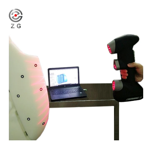 ”
”
Lorenzo Strong, West Coast Customs Sales VP
Read full story
Slashing weeks off reverse engineering farm equipment with Artec Eva
“Eva has literally saved us days if not weeks of work, and that’s no exaggeration. Previously we were spending all that time creating prototypes to test, then that many more hours on alterations to reach the level of perfect, compared to now achieving perfection the first time, and every time, with Eva.”
Mark Taylor, Taylor Attachments
Read full story
User-friendly portable 3D scanner with an inbuilt touchscreen and intuitive UI for easy 3D scanning.
Learn more
Our bestselling 3D scanner. Fast, versatile, and accurate.
Learn more
A metrological structured-light 3D scanner, set apart with its ability to render complex geometry, sharp edges, and thin ribs in high precision.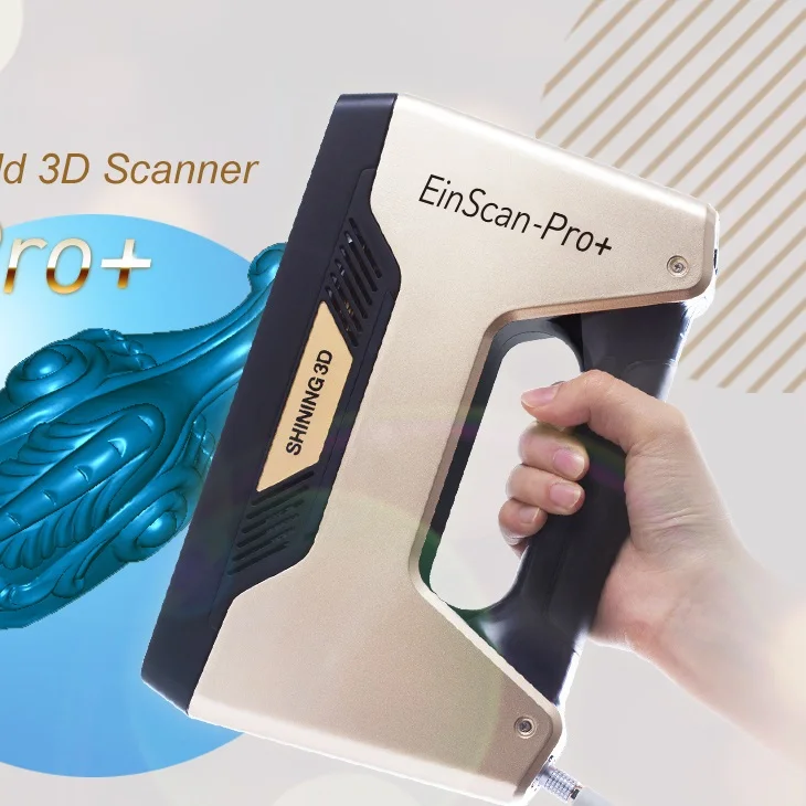
Learn more
Powerful long-range laser 3D scanner with an inbuilt battery, for precise capture of large objects.
Learn more
Metrology-grade desktop 3D scanner for quality control, inspection, jewelry, medical/dental components, etc.
Learn more
Complex motorcycle engine captured by Artec Leo in just 8 minutes
Artec Leo
Pipe bend captured with Artec Micro in only two scans over four minutes
Artec Micro
Motorcycle crankcase captured by Artec Space Spider in 15 minutes
Artec Space Spider
Compound bow captured by Artec Eva in just five minutes
Artec Eva
Artec Ray was used to scan an airplane suspended three meters high.
Artec Ray
Choosing a 3D Scanner for Reverse Engineering
Welcome! The topic of the new review from Top3DShop is reverse engineering or reverse engineering. Today we will introduce our readers to the technology, tell you about the rules for selecting 3D scanners. Consider paid and free programs for reverse engineering.
Definition of reverse engineering
Source: 3daeroscan.com However, in most cases, access to such information is closed. In this case, reverse engineering (reverse engineering) is used. The technology is designed to create a model of a physical object based on the study of its parameters.
A 3D-scanned CAD model can be modified to improve its characteristics, such as increased productivity, longer service life. Reverse engineering is in demand in many areas: from large industrial and repair enterprises to medium and small service workshops, restyling and other areas.
Due to the active use of 3D printing, reverse engineering is becoming more and more popular. Even a user who is just starting to get acquainted with digital technologies can create a model of an object using a 3D scanner and print it on a 3D printer.
ICON restores vintage cars. In his work, he uses different models of 3D scanners to reverse engineer the necessary parts.
Source: 3dreveng.com
The process consists of three stages:
- 1: using scanning, a point cloud is obtained to create a digital copy of the object;
- 2: create a 3D model from the received information;
- 3: prepare the model for production: correct the image, transform it into the required format.
It is important to choose the right equipment for the user's needs. For example, to scan small museum artifacts, it makes no sense to work with a time-of-flight scanner for large-sized objects, as well as to digitize an aircraft fuselage with a high-precision handheld 3D scanner.
Using Creaform HandySCAN 700, NeoMetrix technologies performs metrological control activities and creates projects using reverse engineering technology.
How to make a new one using reverse engineering
Source: 3dcaptura.cz
1. Examine the object. We remind you that to work with reflective surfaces, you must first apply a matting agent, otherwise it will be impossible to digitize them. Apply stickers if necessary.
2. Digitize the part using the 3D scanner. Hard-to-reach areas, such as deep holes, may require additional scanning.
3. Process the received data: remove unnecessary elements, optimize the size, check the accuracy of the stitching of the surfaces.
4. Transfer the grid to the appropriate software.
5. Convert polygonal surfaces to solid. More information about creating 3D models can be found in this article.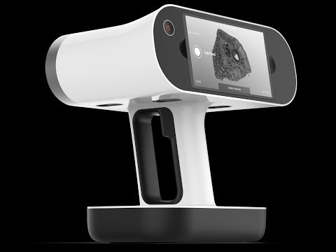
6. If required, make changes to the completed model.
7. Make a new do based on the project using a CNC machine or print it on a 3D printer.
Creaform creates car parts using the Creaform 3D scanner and Autodesk Inventor software.
Cases
Impeller reverse engineering
Source: 3d-scantech.com
The manufacturer was faced with the task of eliminating part defects and improving the production process. The complex geometry of the impeller with many dead corners and recesses, narrow slots did not allow measurements using the CMM probe and other traditional methods. To solve the problem, a 3D laser scanner and reverse engineering technology were used.
Source: 3d-scantech.com
Digitization was performed using ScanTech PRINCE, a high-precision 3D scanner with a resolution of 20 µm, based on blue and red lasers.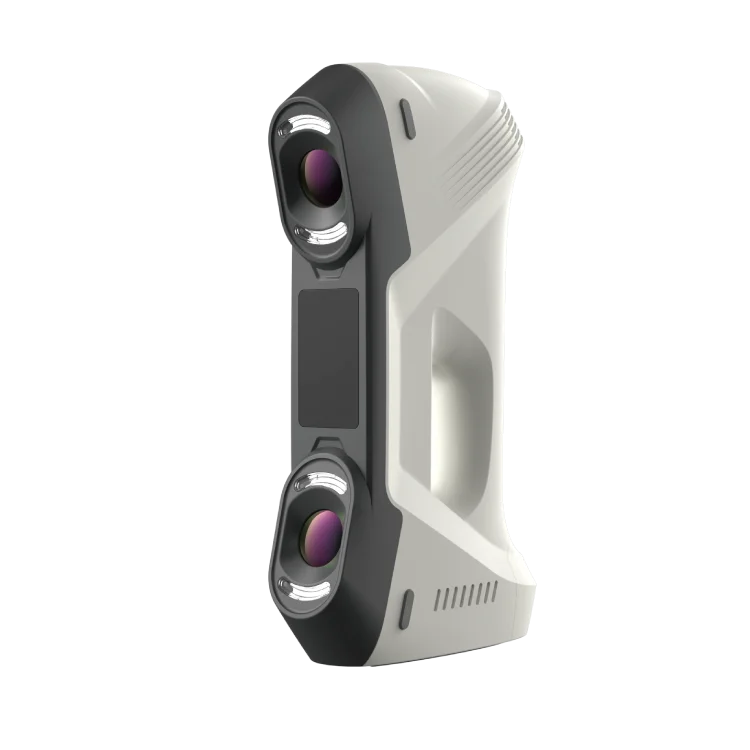 The device quickly switches from one mode to another, works with objects of complex geometry, does not depend on an external light source.
Source: 3d-scantech.com
As a result, an accurate model of the part was created.
Source: 3d-scantech.com
Based on the finished project, you can analyze and correct the object.
Top 3D Shop Case: Part Reconstruction with Reverse Engineering The customer's challenge for Top 3D Shop was to recreate a damaged plastic part.
The process used a RangeVision Pro 3D scanner, reverse engineering and 3D printing.
Stage 1. The size of the part determined the choice of equipment. The length of 300 mm did not allow placing an object in the chamber of a desktop device with a multi-axis platform. Medium-precision 3D scanners for working with large objects were also not suitable for solving this problem. Of the options remained high-precision hand-held scanners or optical desktop models.
Stage 2. Evaluate the geometry of the object. Difficulty level - medium, respectively, requires a scanner with an accuracy of 0.04 - 0.06 mm.
In the photo: models after restoration work.
Stage 3. It is known that the price directly depends on the functionality of the 3D scanner. Models from different manufacturers, such as Scantech, Solutionix, ZGOM, were suitable for solving the problem. Within the budget of the customer, we used the RangeVision Pro scanner, which has proven itself in working with small objects with an accuracy of 0.04 mm.
After digitizing the part, we processed the model and prepared it for 3D printing.
Recommendations for choosing a 3D scanner for reverse engineering
First of all, the choice is influenced by the size of objects. Depending on this parameter, you should determine the type of device and scanning technology.
- For larger items larger than 10,000 mm on either side, TOF scanners are suitable.
 Handheld scanners based on structured illumination or lasers will not cope with the task. Also in this case, to improve the accuracy of the data, you can use photogrammetry.
 - For digitizing objects in the range of 500 to 3000 mm, portable scanners are best suited: laser or optical.
- For scanning objects 100 - 500 mm, the best option is floor-standing (on a stand) or desktop laser and optical devices. Laser models are more expensive than optical counterparts. Some mobile 3D laser scanners are suitable for fast scanning.
- Small objects are best scanned with stationary optical devices. They are of two types: universal and dental.
Universal devices are usually equipped with a multi-axis turntable, or the devices themselves are loosely mounted on axles. This type of device copes well with embossed surfaces.
Dental scanners are equipped with swivel platforms that can be used to mount impression stands and occluders. The devices are characterized by high resolution and accuracy.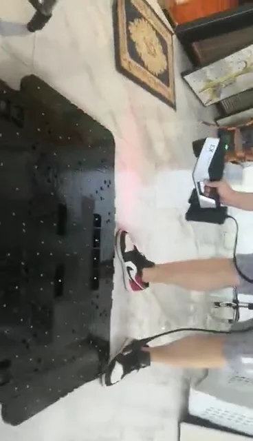
Cases where mobile 3D laser scanners can be used to digitize small objects (from 100 to 500 mm):
- regular scan;
- it is not possible to deliver the object to the location of the stationary device;
- workstation too small for tabletop or floor standing unit;
- the surface of the object is black or highly reflective, making it difficult to grasp with optical instruments.
After selecting equipment depending on the size of objects, it is important to determine the accuracy, tolerances and the need for a metrological device.
The video shows an example of using a Faro Quantum ScanArm HD 3D laser scanner and a Stratasys Dimension 1200es 3D printer to reverse engineer automotive parts.
PO for creating 3D models and reverse engineering
software for obtaining a polygonal model
Source: All3dp. com
com
Most of the programs that are included points and polygonal models. Some software developed for digitizing objects and reverse engineering is compatible by default with models of 3D scanners from well-known manufacturers.
software for transformation of data into solid -state model
GEOMAGIC Essentials
Source: Einscan.com
GEOMAGIC Essentials - partner product of well -known manufacturers of shining 3D and 3D SSTEM import into computer-aided design systems. The software is designed to work with images acquired with Shining 3D EinScan Pro 2x.
The software works in the field of reverse engineering and metrological control. Allows you to create cross sections, restore and align meshes, adjust elements. The program optimizes the work of specialists working with a large amount of information.
Video above: Demonstration of Geomagic Essentials by Gregory George.
Geomagic Design X
Source: 3dsystems.com
Geomagic Design X is a professional software product designed for scanning and designing. The software creates solid models with the ability to edit. Thanks to specially developed algorithms, it is possible to design components that fit perfectly with existing parts.
Point cloud processing, surface fitting to 3D scans with high accuracy and mesh editing, as well as convenient and easy tools for using these functions, allow you to quickly optimize the 3D model received from the scanner, smooth its surfaces, fill holes and prepare it for full comparison with original.
Autodesk Meshmixer
Source: All3dp.com
Autodesk Meshmixer - a popular free set of tools for working with polygonal nets. The software capabilities include automatic analysis and correction of the received images, preparation of models for printing, as well as the calculation of the necessary supports.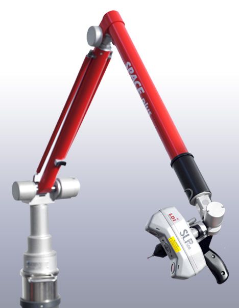 Meshmixer has a clean interface and a large number of free tutorial videos.
Video footage from software developer AutoDesk.
Programs for working with solid-voltage models
SolidWorks
Source: Blog.trimech.com
Solidworks for 3D modeling and reverse design. The standard set of computer-aided design functions is supplemented with tools for modeling molds, weldments and sheet metal parts. Users have access to a large library of parts and components, a lot of analytical capabilities. SOLIDWORKS is recognized as one of the most powerful 3D design software products.
Video: SolidWorks software tutorial.
Solid Edge
Source: youtu.be
Solid Edge Premium can be used free of charge for a year if the project meets certain requirements.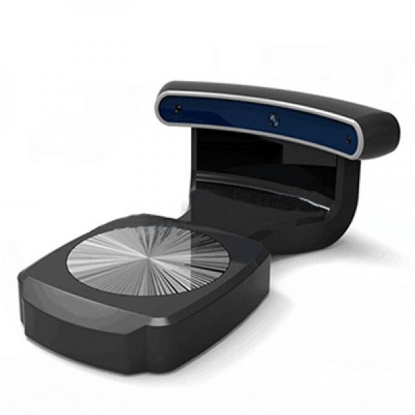 The developer regularly updates the software, creates tutorials, offers help from experts and members of the user community.
On the video: Siemens Software introduces the Solid Edge 2021 software capabilities.
Autodesk Fusion 360
MODAL MODALS. The program and additional modules are free.
In the video: an example of working with a part in Fusion 360.
IP law and reverse engineering
Source: scantech.com
Reverse engineering is closely related to the issue of copyright. The availability of digital equipment and technology makes it possible for unauthorized access to manufacturers' projects, the development of which could have taken a huge amount of effort and investment.
Manufacturers are forced to experiment with intellectual property protection options. For example, equipping products with authentication barcodes.
In the video: digitization and reverse engineering of a car using Creaform Go!SCAN SPARK.
Results
Source: ductim-x.com
Reverse engineering technology is firmly established in modern production. Developers are looking for more process automation, which increases the share of scanning and data processing. Reverse engineering helps to optimize the work of specialists in many areas. Successful experience in the use of 3D scanners expands the scope of their application.
Choose and buy 3D scanners and software for reverse engineering in Top 3D Shop! Only original equipment, official warranty, technical support and quality service.
Read about reverse engineering of parts and subsequent 3D printing
rare details of complex geometric shape. In this article, we will analyze the entire process of reverse engineering (reverse engineering), as well as ways to print the resulting models using the example of automotive parts.
There are two ways to reverse engineer: precise measurements of the original part followed by 3D CAD modeling and 3D scanning. The first method is suitable for parts with a relatively simple shape, and in cases where it is impossible to take accurate measurements with standard measuring instruments, a 3D scanner should be used.
Genuine Part
Scanned objects often have a glare reflective surface, so most parts should be treated with an anti-reflective matte spray before scanning to obtain accurate model geometry.
Parts treated with anti-reflective spray
When scanning large objects, portable hand-held 3D scanners are used, for the use of which, in addition to an anti-reflective spray, it is necessary to apply control marks-stickers for precise positioning of different areas of the part.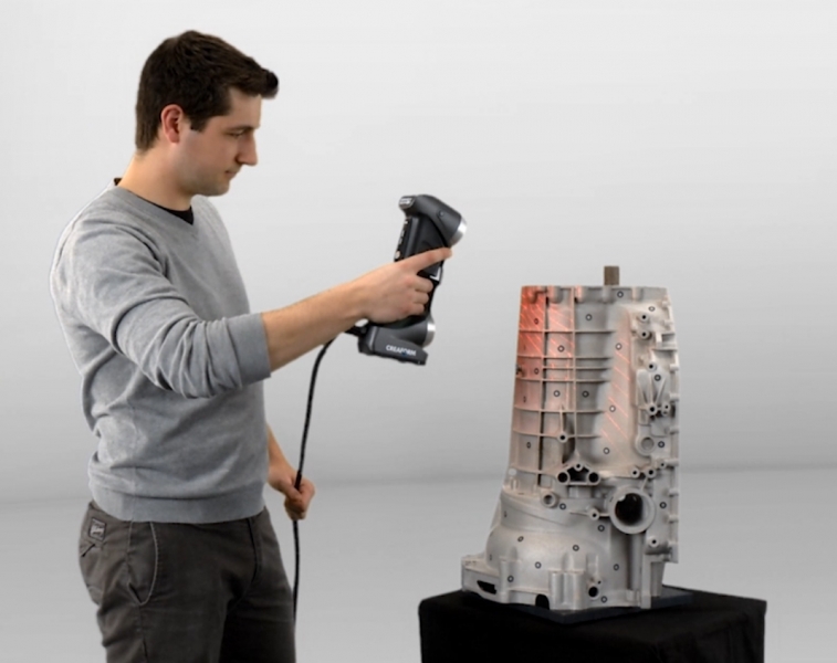 After scanning is completed, a point cloud is formed, it is generated by the scanner program into a polygonal mesh that forms the planes of the 3D model.
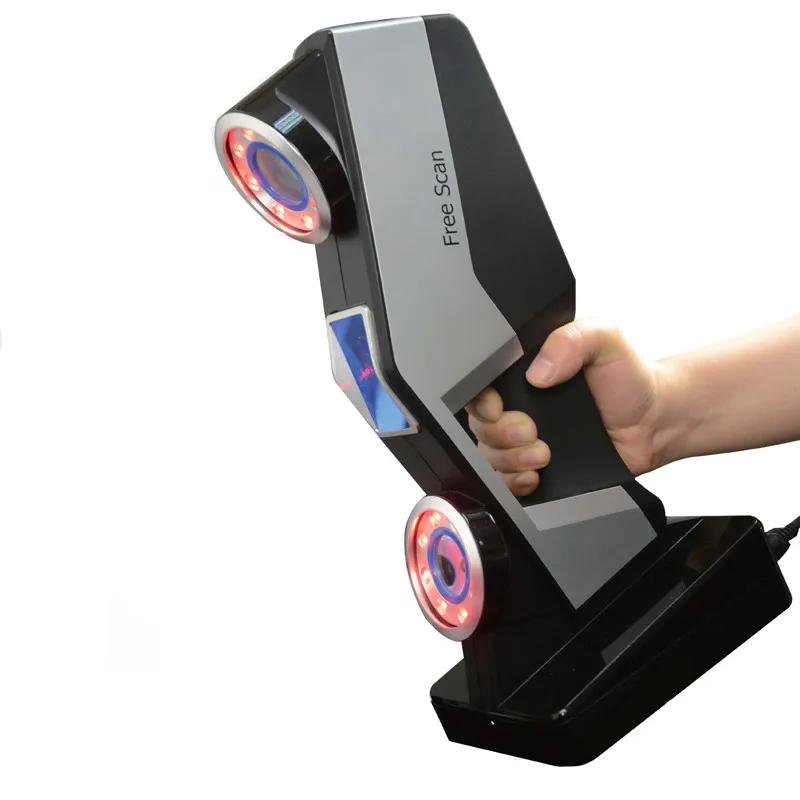
Example of a 3D handheld scanner
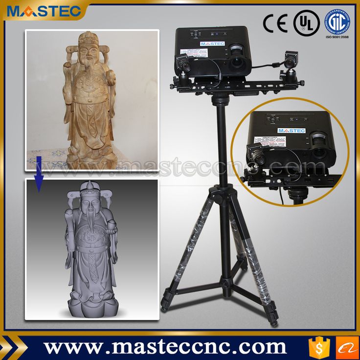
There is also a variety of stationary scanners that are used when working with medium-sized objects. The part is installed on a turntable, which already has position marks, which greatly speeds up the scanning process.
Example of a stationary 3D scanner
A turntable lab scanner is suitable for scanning small items. When installing a part, the scanner creates a laser or optical positioning grid, after which the part is automatically scanned in just 10-15 seconds.
Example of a laboratory 3D scanner
But even with the highest quality 3D scanning, post-processing of the resulting model in CAD systems with tools for reverse engineering is required.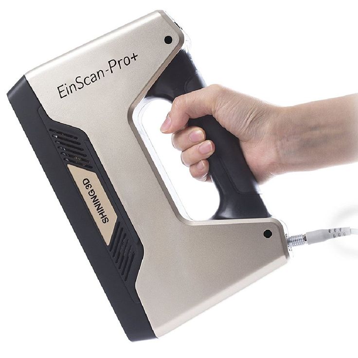 Only after removing excess polygons and adding the missing ones, you can get a complete model ready for 3D printing.
Raw 3D scan
Finished 3D part model
To date, 3D printing is the most appropriate solution for creating single unique parts, as well as for organizing small-scale production, given the high cost and complexity of creating molds for casting.
The choice of 3D printing technology depends mainly on the level of detail required, since FDM plastics and resins for photopolymer printing are comparable in their variety and physical characteristics. Separately, it is worth noting the growing popularity of metal printing using D&S and SLM technologies, which are used as an alternative to expensive metal injection molding.
Printing with metal filament on a Forge1 printer
The main requirement for printing the presented models of automotive parts is resistance to medium physical stress, so we decided to print two sets of parts using FDM and LCD technologies.
For FDM printing, a professional FlashForge Creator 3 Pro printer was chosen, and Esun ABS + was used as a material. The total printing time was 23 hours at a speed of 50 mm/s. The layer height is 0.2 mm, the filling density is 100%.
Installing models in the slicer
FlashForge Creator 3 Pro
Parts made from Esun ABS+ turned out to be strong and at the same time with a high modulus of elasticity, which allows for high bending loads.
3D printed models FlashForge Creator 3 Pro
Phrozen Sonic Mega 8K with Phrozen ABS-like resin was used for LCD printing. Layer height 0.05mm, printing time was 6.5 hours.
Phrozen Sonic Mega 8K with printed parts
Phrozen ABS-like parts have a harder structure and high bending stiffness, and thanks to Phrozen Sonic Mega 8K high-precision printing, the layers on the parts are not visible, which makes this manufacturing method an alternative to plastic injection.