Fix stl for 3d printing
How to Repair STL Files for 3D Printing With the 5 Best (Free) STL Repair Tools
Designers and engineers often need software to adapt, repair, and finalize 3D models for 3D printing. Luckily, the era of manual mesh programming is long gone.
Today, there is a range of dedicated tools available offering both automatic and manual STL repair functions. Automatic wizards will suffice for most models and fix small errors such as holes and loose shells, but models with more critical errors will require a standalone solution.
In this guide, we describe the workflow for repairing STL files and walk through the process with five of the best STL repair software tools for fully repairing models towards 3D print-readiness.
Advanced print preparation tools like PreForm software from Formlabs include an automated repair function. PreForm is free, try it now.
Video Guide
Having trouble finding the best 3D printing technology for your needs? In this video guide, we compare FDM, SLA, and SLS technologies across popular buying considerations.
Watch the Videos
3D designers typically construct models using elaborate surfacing methods. This results in mathematically ‘perfect’ geometry defined by curves and splines. For 3D printing, surfaces are converted to a mesh format that describes geometry as a cloud of connected triangular faces and vertices.
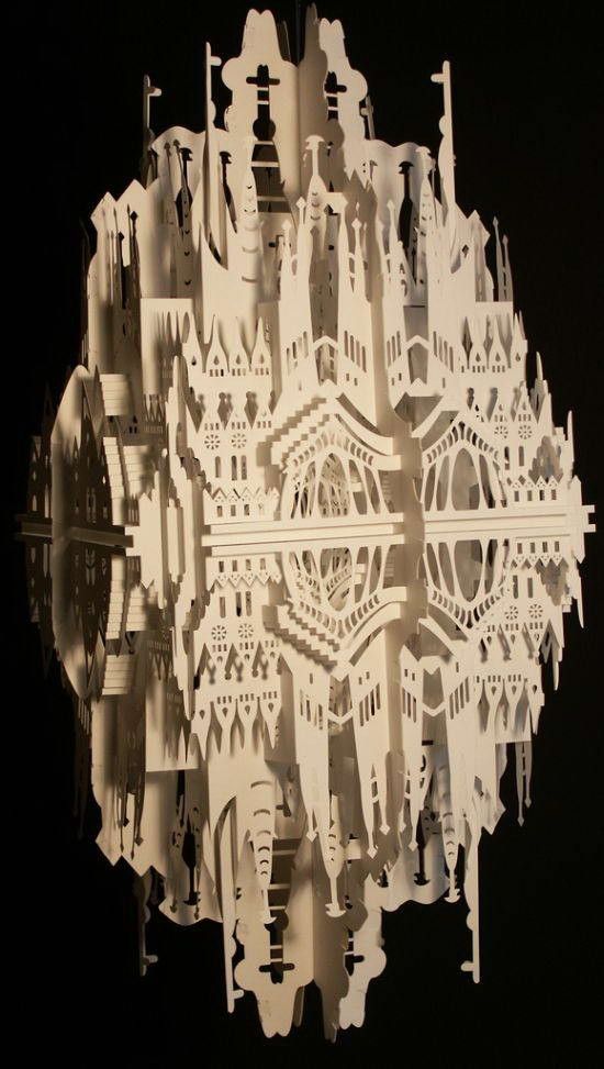
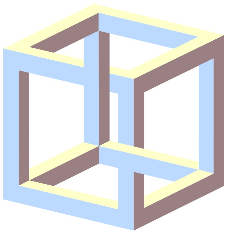
Mesh conversion is like smashing a perfectly smooth mirror, then gluing back together all the bits and pieces to make it look like the original. Done badly, the result is a model with all kinds of edges, holes, and floating parts, as well as areas with many intersecting triangles that do not belong there. Done well, the 3D print is a manifold mesh without holes, indistinguishable from the original design.
A 3D model mesh with various flaws.
A typical STL file repair workflow contains the following steps:
-
Auto-repair. The STL repair software’s wizard will attempt to fix all major errors, including holes, separate shells, and intersections.
-
Separating shells. A mesh consists of collections of connected triangles. It can contain multiple continuous surfaces that ideally are joined together while obsolete ones need removal.
-
Closing holes, bridging gaps. Some comprehensive STL repair programs allow different ways of hole filling, such as planar, tangent, ruled, or freeform.
-
Resolving overlaps and intersections. This typically requires recalculating entire portions of the mesh.
-
Filtering out double faces, double vertices, inverted normals, and sharp, narrow triangles.
-
Stitching open edges and remaining holes.
-
Manual repair by deleting and creating triangles.
-
Remeshing to optimize triangle count.
-
Exporting to the chosen mesh format.
The most popular and storage-friendly format is STL (StereoLiThography), which we will use for this article. We recommend saving the .STL files in a Binary format since it further reduces file size. As described in our Meshmixer tutorial, there are several other useful formats such as AMF, Collada, OBJ, and PLY, with specialized qualities for storing material, color, rendering, 3D scanning, and 3D printing information.
Note: Several software packages contain mesh repair functionalities, such as FreeCAD, SketchUp, 3D Studio Max, and Rhinoceros, as well as online services such as Willit 3D Print, MakePrintable, 3DPrinterOS, SculptGL, and Shapeways. For Formlabs customers, PreForm print preparation software already has Autodesk Netfabb’s automated repair and part packing functions embedded to prepare 3D models upon import. This typically guarantees model integrity, so use additional tools only when requiring more advanced functions.
Sample part
See and feel Formlabs quality firsthand. We’ll ship a free sample part to your office.
Request a Free Sample Part
| Effectiveness | Efficiency | UI | Versatility | Remeshing | Auto-Fixing | Top Features | Who is it for? | Cost | |
|---|---|---|---|---|---|---|---|---|---|
| Meshmixer | ★★★★ | ★★★ | ★★★★ | ★★★★ | ★★★★★ | ★★★★ | UI, Remesh, & Auto-Fix | 3D Artists | Free |
| Netfabb | ★★★ | ★★★ | ★★★ | ★★★★ | ★★★ | ★★★ | Infill & Supports | Engineers | Free (edu) |
| Magics | ★★★ | ★★★ | ★★★ | ★★★★★ | ★★★★ | ★★★ | Manual Repairs | Engineers | Paid |
| Blender | ★★★★ | ★★ | ★★ | ★★★ | ★★★★ | ★ | CG Artists | Free | |
| Meshlab | ★★ | ★ | ★ | ★★★★ | ★★★★★ | ★ | 3D Scanning | Free |
Based on our explorations, the best STL repair tool is Meshmixer. It combines a user-friendly interface with all the options needed to repair complex mesh errors. Its additional possibilities and free availability make it a clear number one. Meshmixer is also a useful tool to edit STL files, resculpt entire sections, as well as optimize and finalize 3D models. Read our Meshmixer tutorial with 15 pro tips for editing STL files for 3D printing.
Autodesk’s Netfabb distinguishes itself by being geared towards engineers with its advanced 3D printing preparation capabilities.
Magics is a professional STL editor solution and offers an enormous variety of STL file repair functions, yet, it often takes more manual repair work. Therefore Magics enters the list in third place.
While Blender is geared more towards 3D modeling and has a complex interface, it still offers most of the required functionalities for successful mesh repairs.
Lastly, Meshlab is a must-have lightweight mesh viewer and editor that makes up for what it lacks in file repair capabilities and user-friendliness with its advanced remeshing scripts.
The following section puts the five STL repair tools to the test using a complex 3D model of a coat hook that has several major errors including holes, gaps, intersections, and floating triangles. The hook needs to be combined with a mounting cylinder to result in a single watertight mesh.
Read on to walk through the step-by-step repair process with the five best STL repair programs.
- Meshmixer
- Meshlab
- Magics
- Blender
- Netfabb
White Paper
In this white paper, learn how 3D scanning paired with 3D printing can be effectively applied to multiple applications across industries, from reverse engineering, restoration, digital dentistry, replication, and more.
Download the White Paper
Meshmixer is a versatile and user-friendly mesh editing program. It is not only possible to optimize a triangle mesh, but also to resculpt entire sections, stylize the model, or add useful features to it.
When loading the coat hook into Meshmixer and initiating Analysis → Inspector we find that indeed, it shows all the mesh errors. Under Shaders, choose the X-ray mode for better visibility. Make sure to select the right Hole Fill Mode before either fixing individual errors by clicking on the dot indicators or running Auto Repair All that in most cases does the job sufficiently.
Use the X-ray shader in the Inspector to view all errors.
An alternative hole repair process is to select the area surrounding the hole and use the Edit → Erase and Fill (F) operation from the popup menu. Setting Type to Smooth MVC produces a good continuous fill. Edit → Make Solid or Edit → Replace and Fill are other alternatives that result in a closed mesh. An additional pass with the RobustSmooth sculpting brush will blend the improved area completely into the model.
In case the model consists of separate shells, go to Edit → Separate Shells and open the Object Browser (Ctrl + Shift + O). Now, progressively select two shells at a time and hit Boolean Union from the popup window. In the newly opened submenu, Precise or Max Quality mode will maintain the intersection curve between both objects, while Fast Approximate is much quicker and usually suffices.
If the Boolean operation fails it results in two red colored objects. In that case, turn the Search Depth parameter up and lower the Target Edge Scale to increase the chance of success. Checking Use Intersection Curves also improves quality. If all else fails, moving one of the shells by a few hundredths of a millimeter in the Edit → Transform section will do the trick.
Auto Repair All will remove floating sections and patch up all boundary loops. In this case, we want to manually connect the gap in one of the struts. This is where the Bridge tool comes in. It works best on straight sections and since this is a gap between circular loops it is best patched up in sections. Choose Edit → Select and highlight the triangles on both sides to be connected. Then hit Edit → Bridge (Ctrl + B) from the popup menu and set the Refine parameter high enough for a smooth connection. Repeat the Bridge command for a few areas around the perimeter of the gap, then use the Inspector to fill the remaining holes. A good error prevention practice is to use Edit → Remesh before repairs in order to increase and homogenize the triangulation in the area concerned.
Connecting a cylindrical gap requires several bridging, remeshing and hole filling operations in Meshmixer.
Meshlab is a software suite that specializes in mesh operations related to 3D scanning data and provides many retriangulation and advanced repair algorithms. A useful one is Filters → Remeshing, Simplification and Construction → Simplification (Quadratic Edge Collapse Decimation) because it recalculates a mesh towards a target number of faces. Checking Planar Simplification will preserve flat surfaces best. An alternative triangle reduction method is Filters → Cleaning and Repairing → Merge Close Vertices.
Floating elements can be detected by right-clicking on the part in the project window and selecting Split in Connected Components. Separate shells can then be individually deleted or combined back with CSG Operation using a Union operator.
Basic repair utilities in Meshlab: Close holes, Boolean, and brush selection.
It is possible to do basic mesh repairs as well with Meshlab. For example, Filters → Cleaning and repairing → Select Self Intersecting Faces → Apply will select all intersecting triangles which can then be removed by pressing Delete. Filters → Cleaning and repairing → Remove Duplicated Faces and Remove Duplicated Vertex are always useful actions to perform. The next step is healing up holes using Filters → Remeshing, Simplification and Construction → Close Holes. The Compute Geometric Measures operation under Filters → Quality Measure and Computations will indicate when a mesh is not watertight. If not, detect the involved areas with Render → Show Non Manif Edges and Show Non Manif Vertices.
For bridging gaps, groups of triangles can be deleted using the Select Faces in a Rectangular Region tool from the toolbar. Hold the Alt key to leave backfaces out of the selection, use Shift + Ctrl + D to deselect. For selecting individual triangles, click the Z-Painting tool on the toolbar and select the red brush icon. Left click to select triangles, right click to erase the selection and hit delete to remove triangles. Because Meshlab does not implement any triangle creation functions, we reside to the surface generation method under Filters → Remeshing, Simplification and Construction → Surface Reconstruction: VCG. With a low enough setting for Voxel Side and high enough value for Geodesic Weighting and Volume Laplacian Iterations, it will result in a smooth manifold mesh.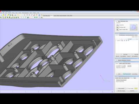 This method is usually recommended over Filters → Remeshing, Simplification and Construction → Screened Poisson Surface Reconstruction. Another alternative method is to generate an Alpha Complex then generate an Alpha Shape which sometimes works with the right values. For remesh operations, Meshlab offers a voxeliser under Filters → Remeshing, Simplification and Construction → Uniform Mesh Resampling which results in a manifold mesh and offers an offset parameter useful for creating hollow parts.
Note: Save meshes after every important operation! Meshlab does not have an Undo function and will require reimporting the original mesh.
Advanced surface reconstruction functions in Meshlab, some more successful than others.
Materialise Magics is a professional 3D print data preparation tool that allows extensive manual control over meshes, including wall thickness analysis, hollowing, remeshing, smoothing, Boolean, and cutting operations, as well as fixing holes, bad edges, and the most complicated triangle errors.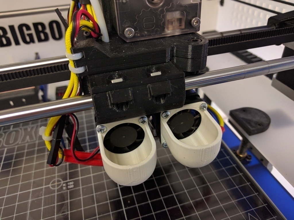
Fixing errors is typically done using the Fix Wizard under the red cross icon. Click on Go to Advised Step opens a diagnostics table to check for different errors to be repaired. For large meshes, it is recommended to uncheck Overlapping triangles and Intersecting triangles and fix the major errors first. After selecting Update, again click Go to Advised Step and then on Automatic Fixing–this will fix most errors.
In case the fix wizard fails to repair bad edges and overlapping triangles, the Stitch function under Stitching in the Fix Wizard menu often proves useful with a high enough tolerance setting. For remaining overlapping triangles, either run the Fix Wizard again or choose Detect Overlapping from the Overlaps section in the Fix Wizard menu. This selects all overlaps that will then be removed by hitting Delete Marked. Similarly, this can be done for intersecting triangles under Triangles → Detect Intersecting. If stitching the remaining gaps does not complete the repair, the Create button now allows filling up the remaining gaps manually. Mesh sections can also manually be marked under the Marking tab on the main menu. Floating sections can be removed under the Noise Shells section. For large non-planar holes, manually filling these using the Freeform option under Holes in the Fix Wizard menu will result in the smoothest fill patch. The Ruled option allows specifying a direction for the hole to follow and is in this case used to bridge the cylindrical gap in one of the flower’s stamens after manually creating a few bridging triangles.
Sometimes the Fix Wizard will not merge different shells in the mesh. To fix that, right click on the part in the Part Pages → Part List menu on the main screen and choose Shells to Parts. This creates separate meshes that when checked can now be combined using the Tools → Boolean (Ctrl + B) function.
Advanced hole filling functions for organic and cylindrical shapes in Magics.
Blender is a free and open-source mesh creation environment, including 3D modeling, rigging, rendering, and animation. Several STL repair functions are available in Edit Mode on the Mesh menu on the lower toolbar. The CellBlender add-on provides a Mesh Analysis tool to check manifoldness and to look for manifold errors. Before commencing any repair scripts, make sure to have the relevant mesh or section selected.
Mesh → Normals → Recalculate Outside (Ctrl + N) flips any triangles with inverted normals. Check the info pane on top for results, in case quads are generated, these can be converted to triangles with Mesh → Faces → Triangulate Faces (Ctrl + T). Mesh → Degenerate → Dissolve removes edges and faces with no area. Remove duplicate vertices to weld edges together with Mesh → Vertices → Remove Doubles.
Bridging, hole filling, and Boolean functions are all represented in Blender.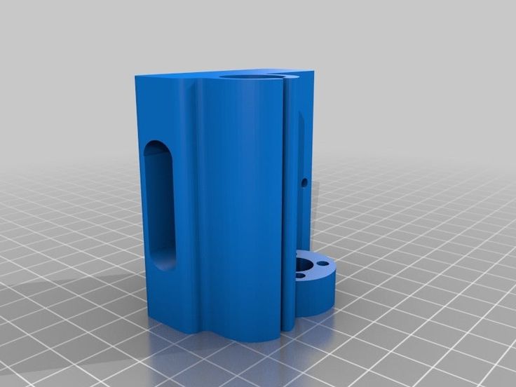
The simplest way to fill a hole in Blender is to first select the boundary loop with Select → Select Boundary Loop or select all non-manifold edges with Select → Select All by Trait → Non Manifold (Shift + Ctrl + Alt + M) and then hit Mesh → Faces → Make Edge/Face (F) or Mesh → Faces → Fill (Alt + F) for an improved fill. Individual triangles can be created by right-clicking an edge or vertex, Shift + right-clicking the second one and pressing F. It is helpful during editing to switch between Vertex Select, Face Select, or Edge Select modes that are indicated by three icons at the bottom toolbar. Selecting a particular area can be done with Select → Circle Select (C) which works similar to brush selection. Change the brush size with the mouse wheel or the numerical plus/minus buttons, deselect holding the Shift key. Mesh → Faces → Beautify Faces (Shift + Alt + F) sometimes works to improve mesh quality in the selected area. Individual boundary loops can be selected using Alt + Right click. With two open boundary loops selected, choose Mesh → Edges → Bridge Edge Loops and the two areas will be smoothly connected.
Choosing Mesh → Vertices → Separate → By loose parts will create one object per shell in the project browser. This makes it possible to delete unwanted mesh objects. Separate shells can be joined together with a Boolean Modifier. If all else fails, implement a Remesh Modifier and increase the octree depth to around 8 or until results are satisfactory. For increasing wall thickness in certain areas, go to Sculpt Mode and use the Inflate brush from the lower menu Brush → Sculpt Tool.
Autodesk Netfabb is an advanced 3D print file preparation tool and its automated repair function is embedded in software such as Formlabs PreForm. It is offered in a Standard, Premium and Ultimate version of which the first two are freely available for educational use.
Netfabb offers additional mesh editing procedures such as hollowing, custom support building, and the Lattice Assistant and Lattice Commander which are great aids in developing lightweight parts. The Ultimate version offers an Optimization Utility that structurally optimizes parts based on applied loads using FEA analysis.
With the File → Import CAD File as Mesh function it is possible not only to import mesh models in various formats, but also native files from Catia, Siemens NX, SolidWorks, SolidEdge, Rhinoceros, ProE, Sketchup plus support for STEP, IGES, SAT, and Parasolid XT files. To import a mesh click File → Add part and check Extended Repair in the dialog. This resolves most errors resulting in a 3D printable file.
Before starting the repair job it is useful to analyze parts. Under the Analysis icon in the taskbar or after right click on the part under Parts → Analyse → New Analysis → Add part it is possible to rapidly check wall thickness. Right-click the part then choose Analyse → New Measurement or pick the ruler icon from the taskbar which allows linear, radius, angular, and wall thickness measurements at specific points.
Advanced Netfabb functions: wall thickness analysis and lattice structures.
Open the Part Repair section by clicking the red Repair icon from the taskbar. If the automated repair script did its job well upon import, the Mesh is Closed and Mesh is Oriented items in the Status tab should be checked in green. In the Actions tab, it is possible to further optimize the file in case intersections pertain to exist. Under Self Intersections, choose Detect and then either opt for Trivial which does a default hole repair, Stitch Triangles, Remove Double Triangles, Remove Degenerate Faces, or Split Off and then Remove the intersections. Wrap Part Surface works similar to voxelisation procedures and leaves only a manifold outer skin. Also, make sure that no noise shells exist under the Shells tab.
Netfabb offers a advanced STL repair capabilities.
When attempting to bridge gaps, Netfabb will rather fill the open holes which require further manual repairs. Tap the Select Surfaces icon on the main toolbar and select the entire hole, then hit Delete. Alternatively, use the Brush Selection tool and use Ctrl + Scrollwheel and the Plus/Minus buttons to alter brush size and selection. With the triangles selected, choose the Remove Selected Triangles icon and manually add missing triangles as well as a few bridging triangles with the Add Triangles button. The Repair → Close all Holes operation will complete the mesh repair task. Finally, we can opt to refine the mesh using the Mesh Edit → Remesh command which recomputes the model based on a Target Edge Length parameter. Check the Maintain Edge option to optimize model integrity around sharp edges.
Looking for the right tool to turn your designs into reality? High-resolution stereolithography (SLA) and selective laser sintering (SLS) 3D printers are fast and cost-effective tools to produce high detail models with a smooth surface finish.
Learn more about 3D printers and see the quality firsthand by requesting a free sample part printed on a Formlabs 3D printer.
Learn More About SLA 3D PrintingLearn More About SLS 3D Printing
Online STL model repair tool for free
Repair your source STL files for printing.
Powered by aspose.com and aspose.cloud
Drop or upload your file
Enter Url
*By uploading your files or using our service you agree with our Terms of Service and Privacy Policy.
STL repairing app is used for 3D printing, it can detect and repair defects from uploaded STL files, like incorrect normal vectors, missing normal vectors, model does not have thickness, unexpected holes, you can also preview before deciding which issues to be fixed. You do not need to install specialized software to open a STL document, just open this application using a web browser, and drag your document into the upload area, and click the view button, your document will open in the browser regardless of whether you are using Windows, Linux, MacOS, Android or even a mobile device.
Aspose.3D STL model repairing
- Support various 3D formats.
- Automatically detect model errors.
- One click to fix all errors.
- Save as AMF, OBJ, STL for printing.
Try other repairing tool: 3DS 3MF AMF ASE DAE DXF DRC FBX GLTF GLB JT OBJ PLY PDF RVM STL U3D VRML X MA USD USDZ
How to use STL repairing app to repair your STL file.
- Click inside the file drop area to upload a file or drag & drop a file.
- Your file will be uploaded and we'll show you file's defects with preview.
- Select the issues we can fix for you, and click the repair button
- Download link of repaired file will be available instantly after repaired.
Stereolithography
STL, abbreviation for stereolithrography, is an interchangeable file format that represents 3-dimensional surface geometry. The file format finds its usage in several fields such as rapid prototyping, 3D printing and computer-aided manufacturing. It represents a surface as a series of small triangles, known as facets, where each facet is described by a perpendicular direction and three points representing the vertices of the triangle.
Read More
-
1
❓ How can I repair 3D file?
First, you need to upload a file for repairing, drag & drop your 3D file or click inside the white area for choose a file. Then click the "REPAIR NOW" button. Our app will list issues we found, choose what issues you want us to repair for you, then you can download your repaired file.
-
2
⏱️ How long does it take to repair 3D?
This repairing app works fast.
 You can repair 3D file in a few seconds.
-
3
🛡 Is it safe to repair 3D file using free repairing app?
Of course! The download link of result files will be available instantly after repaired. We delete uploaded files after 24 hours and the download links will stop working after this period. No one has access to your files. File repairing is absolutely safe.
-
4
💻 Can I repair 3D file on Linux, Mac OS or Android?
Yes, you can use free repairing app on any operating system that has a web browser.
 Our 3D repairing app works online and does not require any software installation.
Other supported repairings
You can also repair into many other file formats. Please see the complete list below.
- 3DS model repairing (3D studio mesh file format)
- 3MF model repairing (3D manufacturing file format)
- AMF model repairing (Additive manufacturing file)
- ASE model repairing (Aseprite sprite file)
- DAE model repairing (Digital asset exchange file format)
- DXF model repairing (Autodesk drawing exchange file format)
- DRC model repairing (Google Draco)
- FBX model repairing (Filmbox interchange file)
- GLTF model repairing (GL transmission format)
- GLB model repairing (Binary glTF file)
- JT model repairing (JT file format)
- OBJ model repairing (OBJ file format)
- PLY model repairing (Polygon file format)
- 3D PDF model repairing (3D PDF)
- RVM model repairing (RVM file format)
- STL model repairing (Stereolithography)
- U3D model repairing (Universal 3D file format)
- VRML model repairing (Virtual reality modeling language)
- X model repairing (DirectX model file)
- MA model repairing (Autodesk Maya)
- USD model repairing (Universal scene description)
- USDZ model repairing (Universal scene description zip archive)
Free Online STL Model Repair Tool
Restore original STL files for printing.
Powered by aspose.com and aspose.cloud
Drag or drop your file
Enter URL
*By uploading your files or using our service, you agree to our Terms of Use and Privacy Policy.
STL repair application is used for 3D printing, it can detect and fix defects from loaded STL files, such as wrong normal vectors, missing normal vectors, model has no thickness, unexpected holes. You can also preview before deciding which issues to fix. You don't need to install any special software to open STL document, just open this application with web browser, drag the document to the download area and click the view button, your document will open in the browser no matter you are using Windows, Linux, MacOS, Android or even mobile device.
Aspose.3D STL Model recovery
- Support for various 3D formats.
- Automatic detection of model errors.
- One click to fix all errors.
- Save as AMF, OBJ, STL for printing.
Try another recovery tool: 3ds 3MF AMF ASE DAE DXF DRC FBX GLTF GLB JT OBJ PLY PDF RVM STL U3D VRML X MA USD USDZ
How to use the STL repair application to repair an STL file.
- Click inside the file drop area to upload a file, or drag and drop a file.
- Your file will be uploaded and we will show you the file defects with a preview.
- Select the issues we can fix for you and click the Fix button.
- The download link for the restored file will be available immediately after the restoration.
Stereolithography
STL, short for Stereolithography, is an interchangeable file format representing 3D surface geometry. The file format finds its way into several areas such as rapid prototyping, 3D printing, and computer-aided manufacturing. It represents a surface as a series of small triangles known as faces, where each face is described by a perpendicular direction and three points representing the vertices of the triangle.
Read more
-
1
❓ How to recover a 3D file?
First, you need to upload a recovery file, drag and drop the 3D file or click inside the white area to select the file.
 Then click the FIX NOW button. Our application will list the issues we have found, select which issues you want us to fix for you and then you can upload the corrected file.
 -
2
⏱️ How long does a 3D repair take?
This repair app is fast. You can recover a 3D file in a few seconds.
-
3
🛡 Is it safe to recover 3D file with free recovery app?
Of course! The link to download the result files will be available immediately after the restoration.
We delete downloaded files after 24 hours and download links stop working after this period. Nobody has access to your files. File recovery is absolutely safe.
-
4
💻 Is it possible to recover a 3D file on Linux, Mac OS or Android?
Yes, you can use the free recovery app on any operating system with a web browser. Our 3D recovery app works online and does not require any software installation.
Other supported repairs
You can also restore to many other file formats. Please see the full list below.
- 3DS Model Recovery (3D Studio Mesh File Format)
- 3MF Model Recovery (3D Production File Format)
- AMF Model Recovery (Additive Manufacturing File)
- ASE Model Recovery (Aseprite Sprite File)
- DAE Model Recovery (Digital Asset Exchange File Format)
- DXF Model Recovery (Autodesk Drawing Interchange File Format)
- DRC Model recovery (Google Draco)
- FBX Model Recovery (Filmbox Exchange File)
- GLTF Model Recovery (GL Transfer Format)
- GLB Model Recovery (GlTF Binary)
- JT Model Recovery (JT File Format)
- OBJ Model recovery (OBJ file format)
- PLY Model Recovery (Polygon File Format)
- 3D PDF Model restoration (3D PDF)
- RVM Model Recovery (RVM File Format)
- STL Model restoration (Stereolithography)
- U3D Model Recovery (Universal 3D File Format)
- VRML Model Recovery (Virtual Reality Modeling Language)
- X Model Recovery (DirectX Model File)
- MA Model Restore (Autodesk Maya)
- USD Restoration of the model (Description of the universal scene)
- USDZ Model restoration (Universal scene description Zip-archive)
Top 10 STL File Healing Features
If you are into 3D design and 3D printing, you know how important it is to fix errors in a model file after it has been converted from CAD to STL format. The project will look perfect, but things can go wrong when printed.
The error may not be noticed, and therefore the software for editing STL files will avoid problems with printing and ensure a successful result. The tools for fixing STL files described in the article will allow you to create a sealed, ready-to-print 3D model.
1. Flip inverted normals
Each 3D model has two sides: an outer side, which is visible after printing, and an inner side, which can only be seen if a side hole is made in the object being designed. The triangles that make up the model (hereinafter referred to as polygons) also have an inner and outer side. The outer side is called the normal.
If the normal is inadvertently rotated by the opposite side (after which it will be directed inward), the 3D printer will not be able to read the model and will determine that the inside of the model needs to be filled, since with this direction of the normal, the inside of the model can now also be considered as the outside .
In general, the printer will not be able to determine when to stop printing and what parts to leave hollow.
Become a qualified 3D technician! Take training courses on working with 3D hardware and software products at the iQB Technologies training center.
2. Fill holes (fill holes)
Sometimes there are not enough polygons, and mesh gaps remain in the model. As in the previous case, due to the lack of information, the 3D printer will not be able to print the model. The machine treats these gaps in the same way as inverted normals: it will not be able to determine the start and end points of the projected object and will either print only the outline (ignoring the inner sides of the layers) or continue printing when it needs to stop. It should be noted that it is possible to intentionally leave holes in the designed object when printing, but for their proper designation it is necessary to correctly place the polygons.
3. Rebuild areas of conflicting polygons (avoid overlapping triangles)
When building complex models, it may be necessary to combine two shapes or extract part of the model (that is, perform Boolean operations), due to which the internal geometry of the model will no longer be optimal, and then you need to remove the conflicting polygons. Such an error is not critical, but printing the model will require more time and material. Conflicting polygons are very difficult to detect because layers can overlap in the finished model.
4. Stitch bad edges (stitch bad edges)
If several polygons are not connected to each other, so-called isolated polygons are formed. In theory, they can be considered as model breaks, since the polygons surrounding such a break cannot be merged with any edge. If there are isolated polygons at the designed object, its model will not be airtight. To create a topologically correct, print-ready model, such polygons must be aligned.
Another variation of this phenomenon is called bad edges ( near bad edges ) and occurs when two polygons are next to each other but have edges that do not touch completely. Such edges are not always visible on the screen, and you need to use STL editing software to identify them. A set of bad edges is called a bad contour ( bad contour ). On the left - a tool for rebuilding areas of conflicting polygons, on the right - merging the sides of isolated polygons
⠀⠀⠀
5. Remove noise shells
In 3D printing, a shell ( shell ) is a group of connected polygons that forms a single 3D object in a file. Shells can either overlap or be separated by a break. One common difficulty with shells is having inverted polygons, or having touching polygons with one side pointing the wrong way in intersecting shells.
It happens that the size of the shell is so small that it becomes redundant within a particular model. Such shells are called areas of artifacts or spatial noise ( noise shells or orphaned shells ) because they have practically no volume. Imagine a crease in a piece of fabric that needs to be smoothed out to get a completely flattened material.
The easiest way to remove such shells is to rotate the inverted polygons to the opposite side, and at the final stage fulfill the requirement that the remaining regular shells in the object you design must be combined into a single solid volume structure. Having multiple shells in a model is not always a bad thing, but it will significantly increase the print time.
Let's explain this situation visually: imagine drawing the outline of a figure on a sheet of paper. If you trace the outline again, it will become thicker. Likewise, more shells means a thicker printed object. When printing a hollow design object (the most common approach, since the model will be lighter and its printing is more profitable), the best way is to print the outer shell (contour) and the inner shell (insert).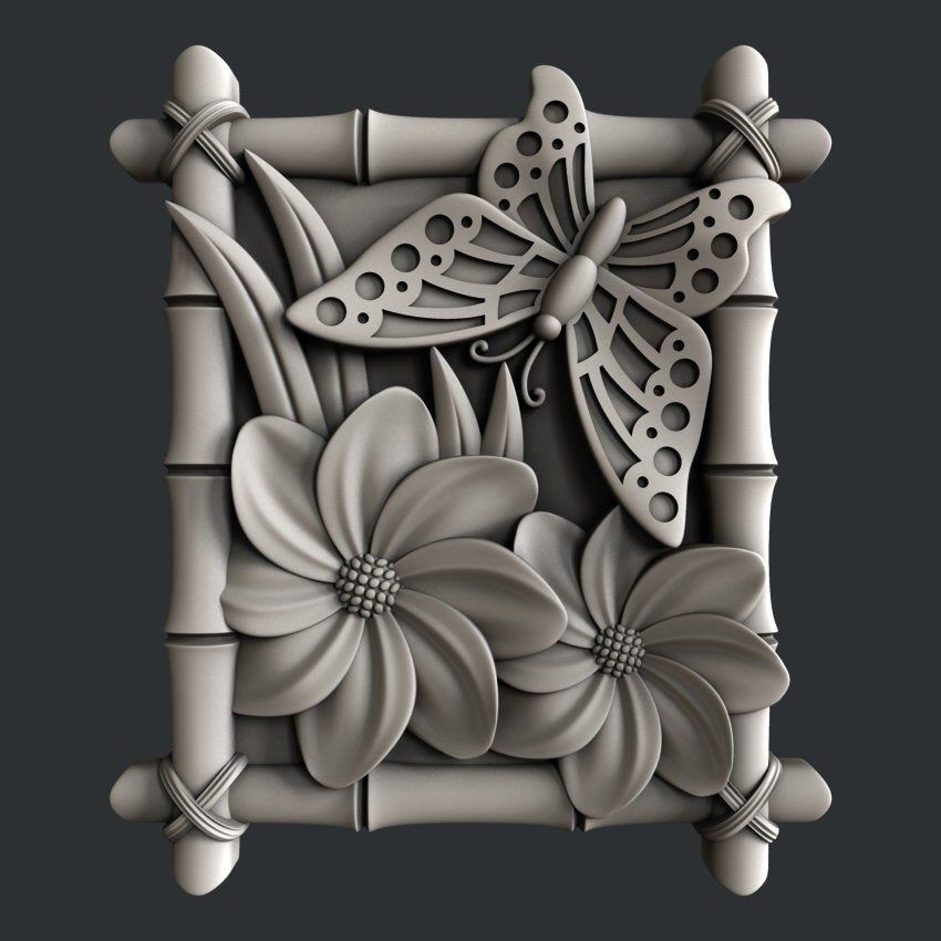 The inner layer consists of inverted normals: from them the computer determines that it is necessary to print a hollow model. In addition, a model with one shell will not be strong enough, and printing will be difficult. At the same time, too many shells will also worsen the model. The recommended number of shells is no more than five.
ShrinkWrap Tool
When working with low quality files, automatic correction of inverted polygons, problematic contours, holes and rough surfaces may not be enough. Materialize's effective repair tool, ShrinkWrap, will come to the rescue. This complex algorithm will cover the model with a thin layer, then peel off this layer and correct serious errors without affecting the detail itself.
Recommended article: Preparing Models for 3D Printing: The Ultimate Guide to Magics
6. Trim or unify intersecting and overlapping triangles
Another problem that novice 3D printers often face is polygon intersection. In this case, you will need to trim the sharp edge and the polygons themselves to get a unified model. Otherwise, the 3D printer will confuse the inside and outside of the model and will not be able to determine how much of the bounding box needs to be filled.
Polygons can also conflict, that is, overlap each other. In this case, the edge of the polygon is shared by two or more faces, as a result of which the 3D printer cannot calculate the print path. So, the printer will separate the model into layers so that the laser or extruder will continue to print the model with the same ribs on top of each other. The program removes duplicate elements on conflicting polygons, which simplifies the calculation process and creates a single solid model.
7. Check wall thickness
It's funny but true: one in five 3D printing orders received by service providers have to be canceled due to incorrect wall thicknesses. This error is very common, which means that it is very important to determine the desired wall thickness.
When working with 3D modeling software, you can design a surface without specifying a wall thickness. However, the 3D printer will need information about the required wall thickness of your object. And here it is necessary to find a compromise: on the one hand, this parameter should be large enough to successfully print a strong part, but at the same time small enough to save material as much as possible.
On the left - the function of trimming / merging intersecting and conflicting polygons, on the right - checking the wall thickness
⠀⠀⠀
Each triangle in the model consumes computer memory. Accordingly, processing STL files with a large number of triangles requires more computing power. Moreover, often a 3D printer cannot print a file that has too many polygons, which means that reducing the number of triangles - an operation also called quantitative optimization of polygons, or mesh decimation - becomes a crucial part of the whole process.