Fix 3d printer
🔥 The definitive guide to solving 3D printing problems by Bitfab
🤬Having problems with your 3D printer? You’ve come to the right place.
In Bitfab we have prepared the definitive guide to solve all your 3D printing problems. Thousands of hours of professional 3D printing behind our back to help you with the setbacks you have with your printer.
And we not only give you the keys to diagnose your printing errors but also the best tips to prevent them from reappearing, fix your printer and calibrate. Pictures, videos and our best tips in a mega article.
👇 Enjoy the guide and use the index if you want to go to directly to the part that interests you.
📖 What do you want to read?
🤬 The most common defects and problems in 3D printing
We have put together a collection of the most common problems that arise when using our 3D printer. They are the same problems that we commonly encounter in our online 3D printing service, and so we have quite a bit of experience dealing with and solving them.
A well calibrated printer, correct lamination and an experienced operator are key to avoiding these problems. By having that you will be able to solve any printing problem.
If you experience any of these issues, follow the instructions we give you and if you still can’t solve them, you have the comment box at the end of the article to tell us your doubts.
❌ Warping, the first layer peels off and the parts bend
Warping is a decreasingly common problem, as the vast majority of modern printers have hot beds. In any case, warping can be caused by the following factors:
- Lack of adhesion to the bed: this can occur due to incorrect height of the nozzle in relation to the base, or poor leveling; but also lack of adhesion to the printing surface.
- Thermal contraction of the upper layers, which when “shrinking” pull on the lower layers. If this occurs, the print surface may even break if it is a BuildTak type, as the sticker will be torn off the bed.
 This can also happen with glass. This happens mostly with materials such as ABS or Nylon, and it is very difficult for it to happen when printing PLA.
Depending on our problem we can look for a solution accordingly:
For the lack of adhesion there are several solutions. If we are using a glass base, it is highly recommended to use some adhesive to increase the fixation of the part. Some known adhesives are the famous Nelly hairspray, or its more professional version 3Dlac. If we are using ABS we can apply a layer of the mixture known as ABS slurry which we can make ourselves by dissolving ABS in a container with acetone.
If your problem is related to thermal contraction, increasing the adhesion will not help you too much since, as we have said, the ABS when deformed can even break our printing base. To solve this problem we can simply cover the printer with whatever we have at home. A large box can work, as well as a more professional enclosure made in a closet.
The idea in this case is to enclose the heat generated by the bed, so that there is not much difference between the temperature of the first layers and the temperature of the upper layers, which are farther away from the heat of the bed.
Here’s an article that we made explaining this problem more in depth: How to avoid warping and cracking in my 3D prints.
❌ Cracking or delamination
Following on from the above problem is cracking or delamination. We talk about cracking when the layers of a part are not well joined, resulting in these layers being separated (hence the name delamination). This problem can be caused by two different reasons:
- Poor adhesion between the layers: the layers do not stick properly to each other.
- Thermal shrinkage: the layers stick together well, but a difference in temperature between different sections of the part causes it to deform, which can cause some layers to separate.
If the problem is lack of adhesion, it is usually due to low of temperature. Most filaments have a temperature range in which they can be printed.
Within this range, lower values will give us a better aesthetic appearance, since the deposition will be “cleaner”. Conversely, higher values will give us better layer adhesion. Printing materials such as ABS at less than the proper temperature often leads to cracking when trying to bond two layers without applying enough heat.
To check if our part is cracking due to lack of adhesion between the layers, we can try to raise the temperature and/or reduce the speed of the layer fan, as excessive cooling can also affect it negatively. Some materials, like ABS, will always be prone to cracking and will be more difficult to control; others like PLA are very easy to print without cracking.
On the other hand, if our problem is thermal contraction the solution is more complicated, as we must manage to create a warmer environment in our printing area. The optimal solution would be to cover our printer, as indicated in the previous point. This can result in some problems, since an excessive temperature can lead to failures in the electronics: missing steps or losing printing artifacts… it can also cause clogging, since there is not enough difference in temperature between the cold zone and the hot zone of the hotend.
In general, avoiding draughts (and the consequent temperature variations) and covering our printer will help, but we must be careful to avoid the problems mentioned.
❌ Layer shift
Layer shifting is a problem that occurs in the form of a displacement on some axis at a certain height. It can occur in the X-axis, the Y-axis or even both simultaneously. The most common causes of layer shifting are:
- Excessive temperature in the motors, or drivers: the electronics in general are not designed to operate continuously at a very high temperature.
- Lack of power in the motors, usually caused by a very low voltage value in the drivers.
- Mechanical failure: it can happen that we have some of our belt’s teeth broken, or there is some debris on the shafts that can cause a jam in the movement of our printer.
 Sometimes a wrongly tightened component can also cause layer displacement defects when the whole shaft moves freely.
A general advice would be to put heatsinks, and if possible ventilation, to the drivers of our board. These components basically take care of sending all the necessary air flow to the motors, so they tend to heat up. Likewise, if our printer operates in very hot environments it would be appropriate to add some heatsink to the X and Y axis motors as well. If the drivers are very hot, you will usually hear a knock, knock, knock on the motors when the drivers are briefly disconnected to give them time to cool down.
Additionally, you can check if your printer has drivers with adjustable voltage, and if so, you can increase this voltage slightly by carefully turning the potentiometer on each driver. Be careful when doing this, and always do it with the printer turned off or using a ceramic screwdriver to avoid short-circuiting with a metal screwdriver. If you turn up the power on the motors too much you risk falling into the overheating problem again.
Finally, check that the shafts of your printer are clean and free from obstructions. Also check that the belts and bearings are not too tight (if the bearings are tightened with flanges or screws). Shafts that do not move well, over-tightened belts… cause motors to work harder and may lose steps.
❌ Z-wobble
This problem can be difficult to identify, as it is often not easy to distinguish it from a simple inconsistency in the extrusion. To identify it we must look at whether this inconsistency is repeated on a regular basis. If it seems random, or just noise in general, your problem is probably not z-wobble but an extrusion problem. Conversely, if there seems to be a pattern that repeats periodically such as waves on the surface, you may well have a problem with your Z-axis.
This problem is mostly due to structural failures in the construction of the machine, and is difficult to solve without making major modifications to our machine chassis. First of all check that all the parts are properly assembled, maintaining the perpendicularity and making sure that there are no loose screws.
Try to tighten all the screws on the couplers that connect the z-axis motors to the spindles. Also check that there is no wobble between the spindle and the trapezoid nut. It is complicated to give a correct solution, because the axis needs some freedom to move to compensate small errors in the chassis, such as corners that are not perfectly perpendicular.
A good solution that is not too expensive is to replace the motor-coupler-spindle assembly with a motor with a built-in spindle. We can also add reinforcements to our printer so that the frame of the printer does not wobble at the top.
❌ Stringing
Stringing is one of the most common problems in novice parts in the world of 3D printing, so if your parts have a lot of strings don’t worry, it’s totally normal and quite easy to solve.
Stringing appears when, as the hotend moves between two sections of our print, a small amount of plastic drips off and sticks to both sections, leaving a small thread in between.
This problem can be caused by the use of a bad quality hotend, but usually the machines have a hotendsn of sufficient quality, so the problem almost always comes from bad lamination in the slicer.
The most important parameters you should check in your slicer to minimize the stringing are the following:
- Temperature
- Retraction distance
- Retraction speed
Temperature is a vital factor and probably one of the 5 most important settings in your profile. If you have a lot of stringing you are almost certainly melting at too high a temperature. Remember that all materials have a range of temperatures in which they can be printed, so try lowering the temperature and bringing it closer to the lower limit recommended by the manufacturer. If you are already using a very low temperature and still have stringing, check the following points.
While it is not possible to “suck” plastic out of the nozzle, as no negative pressure can be created, it is possible to minimize the pressure on the nozzle by pulling the filament out of the hot zone of our hotend. The shrinkage distance is very dependent on our printer, as both the melter and extruder and the type of extrusion (direct or bowden) must be considered. Most bowden printers perform well with a shrinkage value between 3mm and 6mm, and direct extrusion printers between 0.5mm and 2mm.
The speed of retraction is another important factor, as the higher the speed the lower the stringing. This speed will depend on the motor of our extruder and also on the type of extrusion (1:1 vs 3:1 like the Titan extruder). Generally values between 40 mm/s and 60 mm/s usually work, but if you have any doubt, please ask in a forum or group dedicated to your specific printer.
Additionally, almost all slicers or laminators have different more advanced settings that can help reduce the stringing, but these will only be of importance if the three previous ones are well adjusted. This is a very broad topic and we could make an exclusive guide about this problem, so if you want to see it, leave us a comment!
❌ Overheating, curling
One of the easiest problems to diagnose is overheating.
As we can see in the image, melting our plastic at an excessive temperature will cause the parts to look deformed, with the center of the layer sunken. This is because when melted at too high a temperature, the material does not have time to cool down, and that is why the layers can collapse or sag.
These deformations will be much more pronounced in small areas, such as small peaks of our part, where instead of a clean figure, a deformed churro will remain.
The solution to this problem is simple: lower the temperature. We must also play with the values of the layer fan, since a high temperature can favor a more fluid extrusion and we can compensate this temperature with a good cooling. In this way the material will be cooled down quickly and we will be able to obtain optimal results.
❌ Elephant’s foot
The elephant foot is a defect consisting of the expansion in the horizontal plane of the first layers of our part. It can occur due to two things or, normally, a combination of both: the nozzle is too close to the bed or the temperature of the bed is too high.
If the nozzle is too close to the bed, it is obvious that the first layers will be more flattened and therefore expand in the XY plane. To solve this problem we must correctly level our first layer, as indicated in a previous section of this article.
An excessive bed temperature (say, 90 or 100 degrees for PLA) can cause the newly deposited plastic to expand and deform, causing this very characteristic effect.
❌ Ghosting, ringing
The best article on this topic on the internet is the 3D Campy post by 3DSpana about ghosting, because he dedicated himself to try different combinations and components, taking pictures of the results, so you can see how decreasing the weight of the axes affects ghosting. If you prefer it on video, here’s the summary:
😍 Keys to print correctly with your printer
You’ve seen the list of problems we’ve collected. Now you have to know how to DO things.
Knowing your printer and laminator is the key to error and defect-free printing, so here are some tips to avoid problems and help you diagnose and fix them:
✅ Printing speeds
One of the most common mistakes we find on beginners is wanting to print too quickly on their first parts.
The printing speed is one of the most important printing parameters to obtain the best printing quality and an excess of speed affects the part very negatively for many reasons: vibration, extrusion problems, overheating, loss of steps…
One of the first things you have to do when you encounter a problem is to reduce the printing speed to see if it is solved. We usually print almost all parts between 40 and 60mm/s, no more is needed for most cases. In a printing service the most important thing is reliability and when you are looking for reliability it is best to print at reasonable speeds so you don’t have to throw the parts away.
It is not necessary to print your parts at 100mm/s, especially the first ones. Yes, we all know someone who does it and gets it done, but it’s not the best way to make sure they come out right.
✅ Bed adjustment and leveling
Learning to set the bed correctly level and the extruder at the right height is one of the first steps we take with a new 3D printer.
Here’s what a properly adjusted bed looks like: the height of the first layer has to be correct across the entire surface of the bed.
First layer too close
If your first layer is too close to the printing surface, you can cause jams, scratches on the bed, parts with the wrong dimensions, elephant foot…
Correct first layer
When the first layer is correct, the threads deposited by the extruder touch each other and are not too flat against the bed.
First layer too separate
A very separate first layer can be noticed by the separate threads.
Parts printed in this way are usually detached from the bed or warp.
And how do you properly level a hot bed? Our preferred technique is paper in the corners. It is not necessary to have a printer with self-leveling, the best thing is to have a reliable and well calibrated printer to print with quality.
✅ How to prevent and fix extruder clogging
Extrusion jams are the number one cause of failure on a farm like ours. You may have mastered your printer but the jams are always going to be there, so it’s critical to understand them and be able to prevent and fix them.
If you don’t yet understand how a 3D printer extrusion works and what the common terms for referring to them are, you can first check out our guide to 3D extruders.
Causes for clogging
Clogs arise from many different causes, sometimes in conjunction with each other. I believe the best way to solve them is to first understand all those causes and then try a series of techniques that can help fix them.
- Contamination at the tip and print canal. Impurities that are deposited in the print canal or at the tip of the nozzle and hinder or completely block the flow of the filament.
- PTFE/teflon degraded. Teflon hotends in the hot zone require maintenance of the Teflon, which when degraded clogs the filament flow.
- Extruder problems. Maybe your extruder is not working properly:
- Too much tension or too little tension in the dock
- Low voltage in the driver that does not give enough power to the motor
- Dirty thrust wheel, with teeth covered with filament debris
- Any loose or broken parts
- Scratching the filament. This is very, very important to understand. When we see the scratched filament, nibbled by the extruder wheel, it is not always the cause of the clogging. All printing clogs, whatever the cause, end up scratching of the filament. And only those clogs that are due to spring tension and excessive shrinkage are the root cause of the clog itself.
- Tip scratching the base. If the first layer is too low, it can interrupt the flow of the melted plastic and quickly cause a clog in the extrusion system.
- Watch out for shrinkage. A part with a lot of very fast retractions can end up scratching the filament. And long, slow retractions can overheat the cold zone of the extruder and cause clogging as well. In general, retractions won’t cause your clogs, but you should always keep an eye on them.
- Poor cooling. Cooling is a fundamental variable in all-metal hotends. If your extruder is 100% metal like the E3D V6 you have to be very careful with this and with excessive shrinkage.
Unclog the nozzle with acupuncture needles
The technique of passing an acupuncture needle through the printhead is most useful if the real cause of your clog is an impurity. The nozzles themselves last many hundreds or even thousands of hours of use, so you will almost never have to change them.
Most likely a particle has been deposited in the nozzle and you should be able to get it out with the needle. We heat the head and stick the needle while hot, and then pull out the filament with the particles that might be causing the clogging embedded in the molten filament.
Repeat this process until the plastic comes out of the nozzle again easily.
Hot and cold pulling
The pulling takes a little longer to do than using the acupuncture needle, but it cleans the impurities better and also takes away the filth not only from the tip, but from the whole interior of the hotend.
They are easier to explain with a video like the one below:
Teflon switching
In hotends with Teflon liner it is necessary to change this component, in general, every several hundred hours. The Teflon or PTFE liner is a small tube that goes in the hot zone of your hotend to guide the filament in the last centimeters of run, and that is degraded due to the temperature it reaches. Changing it is a job that you will have to learn to do to properly maintain your printer.
Before the tube degrades completely, you will notice that your printer is having more and more trouble printing, the filament thread that comes out is thinner and it’s harder for it to deposit material on the parts that you print faster.
In every printer the change of Teflon is different, but here is the example of the Hephestos 2 from BQ to help you understand it better.
Adjusting the printing parameters
There are clogs that can occur because our laminate is not well adapted to the type of part and printer we are going to use.
To allow your printer to extrude more easily you can try:
- Printing slower
- Printing at a higher temperature
- Printing thinner layers
- Reducing the flow rate if you have more than 100%
These are all tricks that reduce the requirements on the extruder and melter because they require less flow through the hotend and heat the plastic to make it more fluid.
Retractions can also influence extrusion problems:
- Too many or too fast retractions can result in scratching of the filament in the extruder.
- Too long or too slow retractions can cause cooling problems in your melter (especially if it is all-metal) or end up clogging the plastic in the cold zone of the melter.
If you don’t know how to fix it, dissasemble the extruder and hotend
The best way to attack a mechanical problem that you don’t know how to solve is to proceed to disassemble what you want to fix. Taking apart a hotend and an extruder is quite simple and will allow you to see inside what is happening and reflect on the problem.
When you dismantle your extruder you will notice that there are some broken parts, dirt somewhere, some loose screws…
If you disassemble the hotend you will be able to see the state of the Teflon, the tension of the hotend threads and if there is print residue deposited in the filament canal.
In either case, take the opportunity to clean the parts to prevent errors in the future.
👋 That’s it for the 3D printing troubleshooting guide by Bitfab
Thank you so much for getting this far.
If you have any doubt or a different problem just put it in the comments and we will help you solve it, or maybe even add it to the rest of the problems 😁
👋 Greetings and thanks again!
How to Repair STL Files for 3D Printing With the 5 Best (Free) STL Repair Tools
Designers and engineers often need software to adapt, repair, and finalize 3D models for 3D printing. Luckily, the era of manual mesh programming is long gone.
Today, there is a range of dedicated tools available offering both automatic and manual STL repair functions. Automatic wizards will suffice for most models and fix small errors such as holes and loose shells, but models with more critical errors will require a standalone solution.
In this guide, we describe the workflow for repairing STL files and walk through the process with five of the best STL repair software tools for fully repairing models towards 3D print-readiness.
Advanced print preparation tools like PreForm software from Formlabs include an automated repair function. PreForm is free, try it now.
Video Guide
Having trouble finding the best 3D printing technology for your needs? In this video guide, we compare FDM, SLA, and SLS technologies across popular buying considerations.
Watch the Videos
3D designers typically construct models using elaborate surfacing methods. This results in mathematically ‘perfect’ geometry defined by curves and splines. For 3D printing, surfaces are converted to a mesh format that describes geometry as a cloud of connected triangular faces and vertices.
Mesh conversion is like smashing a perfectly smooth mirror, then gluing back together all the bits and pieces to make it look like the original. Done badly, the result is a model with all kinds of edges, holes, and floating parts, as well as areas with many intersecting triangles that do not belong there. Done well, the 3D print is a manifold mesh without holes, indistinguishable from the original design.
A 3D model mesh with various flaws.
A typical STL file repair workflow contains the following steps:
-
Auto-repair. The STL repair software’s wizard will attempt to fix all major errors, including holes, separate shells, and intersections.
-
Separating shells. A mesh consists of collections of connected triangles. It can contain multiple continuous surfaces that ideally are joined together while obsolete ones need removal.
-
Closing holes, bridging gaps. Some comprehensive STL repair programs allow different ways of hole filling, such as planar, tangent, ruled, or freeform.

-
Resolving overlaps and intersections. This typically requires recalculating entire portions of the mesh.
-
Filtering out double faces, double vertices, inverted normals, and sharp, narrow triangles.
-
Stitching open edges and remaining holes.
-
Manual repair by deleting and creating triangles.
-
Remeshing to optimize triangle count.
-
Exporting to the chosen mesh format.
The most popular and storage-friendly format is STL (StereoLiThography), which we will use for this article. We recommend saving the .STL files in a Binary format since it further reduces file size. As described in our Meshmixer tutorial, there are several other useful formats such as AMF, Collada, OBJ, and PLY, with specialized qualities for storing material, color, rendering, 3D scanning, and 3D printing information.
Note: Several software packages contain mesh repair functionalities, such as FreeCAD, SketchUp, 3D Studio Max, and Rhinoceros, as well as online services such as Willit 3D Print, MakePrintable, 3DPrinterOS, SculptGL, and Shapeways. For Formlabs customers, PreForm print preparation software already has Autodesk Netfabb’s automated repair and part packing functions embedded to prepare 3D models upon import. This typically guarantees model integrity, so use additional tools only when requiring more advanced functions.
Sample part
See and feel Formlabs quality firsthand. We’ll ship a free sample part to your office.
Request a Free Sample Part
| Effectiveness | Efficiency | UI | Versatility | Remeshing | Auto-Fixing | Top Features | Who is it for? | Cost | |
|---|---|---|---|---|---|---|---|---|---|
| Meshmixer | ★★★★ | ★★★ | ★★★★ | ★★★★ | ★★★★★ | ★★★★ | UI, Remesh, & Auto-Fix | 3D Artists | Free |
| Netfabb | ★★★ | ★★★ | ★★★ | ★★★★ | ★★★ | ★★★ | Infill & Supports | Engineers | Free (edu) |
| Magics | ★★★ | ★★★ | ★★★ | ★★★★★ | ★★★★ | ★★★ | Manual Repairs | Engineers | Paid |
| Blender | ★★★★ | ★★ | ★★ | ★★★ | ★★★★ | ★ | CG Artists | Free | |
| Meshlab | ★★ | ★ | ★ | ★★★★ | ★★★★★ | ★ | 3D Scanning | Free |
Based on our explorations, the best STL repair tool is Meshmixer. It combines a user-friendly interface with all the options needed to repair complex mesh errors. Its additional possibilities and free availability make it a clear number one. Meshmixer is also a useful tool to edit STL files, resculpt entire sections, as well as optimize and finalize 3D models. Read our Meshmixer tutorial with 15 pro tips for editing STL files for 3D printing.
Autodesk’s Netfabb distinguishes itself by being geared towards engineers with its advanced 3D printing preparation capabilities.
Magics is a professional STL editor solution and offers an enormous variety of STL file repair functions, yet, it often takes more manual repair work. Therefore Magics enters the list in third place.
While Blender is geared more towards 3D modeling and has a complex interface, it still offers most of the required functionalities for successful mesh repairs.
Lastly, Meshlab is a must-have lightweight mesh viewer and editor that makes up for what it lacks in file repair capabilities and user-friendliness with its advanced remeshing scripts.
The following section puts the five STL repair tools to the test using a complex 3D model of a coat hook that has several major errors including holes, gaps, intersections, and floating triangles. The hook needs to be combined with a mounting cylinder to result in a single watertight mesh.
Read on to walk through the step-by-step repair process with the five best STL repair programs.
- Meshmixer
- Meshlab
- Magics
- Blender
- Netfabb
White Paper
In this white paper, learn how 3D scanning paired with 3D printing can be effectively applied to multiple applications across industries, from reverse engineering, restoration, digital dentistry, replication, and more.
Download the White Paper
Meshmixer is a versatile and user-friendly mesh editing program. It is not only possible to optimize a triangle mesh, but also to resculpt entire sections, stylize the model, or add useful features to it.
When loading the coat hook into Meshmixer and initiating Analysis → Inspector we find that indeed, it shows all the mesh errors. Under Shaders, choose the X-ray mode for better visibility. Make sure to select the right Hole Fill Mode before either fixing individual errors by clicking on the dot indicators or running Auto Repair All that in most cases does the job sufficiently.
Use the X-ray shader in the Inspector to view all errors.
An alternative hole repair process is to select the area surrounding the hole and use the Edit → Erase and Fill (F) operation from the popup menu. Setting Type to Smooth MVC produces a good continuous fill. Edit → Make Solid or Edit → Replace and Fill are other alternatives that result in a closed mesh. An additional pass with the RobustSmooth sculpting brush will blend the improved area completely into the model.
In case the model consists of separate shells, go to Edit → Separate Shells and open the Object Browser (Ctrl + Shift + O). Now, progressively select two shells at a time and hit Boolean Union from the popup window. In the newly opened submenu, Precise or Max Quality mode will maintain the intersection curve between both objects, while Fast Approximate is much quicker and usually suffices.
If the Boolean operation fails it results in two red colored objects. In that case, turn the Search Depth parameter up and lower the Target Edge Scale to increase the chance of success. Checking Use Intersection Curves also improves quality. If all else fails, moving one of the shells by a few hundredths of a millimeter in the Edit → Transform section will do the trick.
Auto Repair All will remove floating sections and patch up all boundary loops. In this case, we want to manually connect the gap in one of the struts. This is where the Bridge tool comes in. It works best on straight sections and since this is a gap between circular loops it is best patched up in sections. Choose Edit → Select and highlight the triangles on both sides to be connected. Then hit Edit → Bridge (Ctrl + B) from the popup menu and set the Refine parameter high enough for a smooth connection. Repeat the Bridge command for a few areas around the perimeter of the gap, then use the Inspector to fill the remaining holes. A good error prevention practice is to use Edit → Remesh before repairs in order to increase and homogenize the triangulation in the area concerned.
Connecting a cylindrical gap requires several bridging, remeshing and hole filling operations in Meshmixer.
Meshlab is a software suite that specializes in mesh operations related to 3D scanning data and provides many retriangulation and advanced repair algorithms. A useful one is Filters → Remeshing, Simplification and Construction → Simplification (Quadratic Edge Collapse Decimation) because it recalculates a mesh towards a target number of faces. Checking Planar Simplification will preserve flat surfaces best. An alternative triangle reduction method is Filters → Cleaning and Repairing → Merge Close Vertices.
Floating elements can be detected by right-clicking on the part in the project window and selecting Split in Connected Components. Separate shells can then be individually deleted or combined back with CSG Operation using a Union operator.
Basic repair utilities in Meshlab: Close holes, Boolean, and brush selection.
It is possible to do basic mesh repairs as well with Meshlab. For example, Filters → Cleaning and repairing → Select Self Intersecting Faces → Apply will select all intersecting triangles which can then be removed by pressing Delete. Filters → Cleaning and repairing → Remove Duplicated Faces and Remove Duplicated Vertex are always useful actions to perform. The next step is healing up holes using Filters → Remeshing, Simplification and Construction → Close Holes.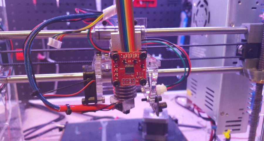 The Compute Geometric Measures operation under Filters → Quality Measure and Computations will indicate when a mesh is not watertight. If not, detect the involved areas with Render → Show Non Manif Edges and Show Non Manif Vertices.
For bridging gaps, groups of triangles can be deleted using the Select Faces in a Rectangular Region tool from the toolbar. Hold the Alt key to leave backfaces out of the selection, use Shift + Ctrl + D to deselect. For selecting individual triangles, click the Z-Painting tool on the toolbar and select the red brush icon. Left click to select triangles, right click to erase the selection and hit delete to remove triangles. Because Meshlab does not implement any triangle creation functions, we reside to the surface generation method under Filters → Remeshing, Simplification and Construction → Surface Reconstruction: VCG. With a low enough setting for Voxel Side and high enough value for Geodesic Weighting and Volume Laplacian Iterations, it will result in a smooth manifold mesh. This method is usually recommended over Filters → Remeshing, Simplification and Construction → Screened Poisson Surface Reconstruction. Another alternative method is to generate an Alpha Complex then generate an Alpha Shape which sometimes works with the right values. For remesh operations, Meshlab offers a voxeliser under Filters → Remeshing, Simplification and Construction → Uniform Mesh Resampling which results in a manifold mesh and offers an offset parameter useful for creating hollow parts.
Note: Save meshes after every important operation! Meshlab does not have an Undo function and will require reimporting the original mesh.
Advanced surface reconstruction functions in Meshlab, some more successful than others.
Materialise Magics is a professional 3D print data preparation tool that allows extensive manual control over meshes, including wall thickness analysis, hollowing, remeshing, smoothing, Boolean, and cutting operations, as well as fixing holes, bad edges, and the most complicated triangle errors.
Fixing errors is typically done using the Fix Wizard under the red cross icon. Click on Go to Advised Step opens a diagnostics table to check for different errors to be repaired. For large meshes, it is recommended to uncheck Overlapping triangles and Intersecting triangles and fix the major errors first. After selecting Update, again click Go to Advised Step and then on Automatic Fixing–this will fix most errors.
In case the fix wizard fails to repair bad edges and overlapping triangles, the Stitch function under Stitching in the Fix Wizard menu often proves useful with a high enough tolerance setting. For remaining overlapping triangles, either run the Fix Wizard again or choose Detect Overlapping from the Overlaps section in the Fix Wizard menu. This selects all overlaps that will then be removed by hitting Delete Marked. Similarly, this can be done for intersecting triangles under Triangles → Detect Intersecting. If stitching the remaining gaps does not complete the repair, the Create button now allows filling up the remaining gaps manually. Mesh sections can also manually be marked under the Marking tab on the main menu. Floating sections can be removed under the Noise Shells section. For large non-planar holes, manually filling these using the Freeform option under Holes in the Fix Wizard menu will result in the smoothest fill patch. The Ruled option allows specifying a direction for the hole to follow and is in this case used to bridge the cylindrical gap in one of the flower’s stamens after manually creating a few bridging triangles.
Sometimes the Fix Wizard will not merge different shells in the mesh. To fix that, right click on the part in the Part Pages → Part List menu on the main screen and choose Shells to Parts. This creates separate meshes that when checked can now be combined using the Tools → Boolean (Ctrl + B) function.
Advanced hole filling functions for organic and cylindrical shapes in Magics.
Blender is a free and open-source mesh creation environment, including 3D modeling, rigging, rendering, and animation. Several STL repair functions are available in Edit Mode on the Mesh menu on the lower toolbar. The CellBlender add-on provides a Mesh Analysis tool to check manifoldness and to look for manifold errors. Before commencing any repair scripts, make sure to have the relevant mesh or section selected.
Mesh → Normals → Recalculate Outside (Ctrl + N) flips any triangles with inverted normals. Check the info pane on top for results, in case quads are generated, these can be converted to triangles with Mesh → Faces → Triangulate Faces (Ctrl + T). Mesh → Degenerate → Dissolve removes edges and faces with no area. Remove duplicate vertices to weld edges together with Mesh → Vertices → Remove Doubles.
Bridging, hole filling, and Boolean functions are all represented in Blender.
The simplest way to fill a hole in Blender is to first select the boundary loop with Select → Select Boundary Loop or select all non-manifold edges with Select → Select All by Trait → Non Manifold (Shift + Ctrl + Alt + M) and then hit Mesh → Faces → Make Edge/Face (F) or Mesh → Faces → Fill (Alt + F) for an improved fill. Individual triangles can be created by right-clicking an edge or vertex, Shift + right-clicking the second one and pressing F. It is helpful during editing to switch between Vertex Select, Face Select, or Edge Select modes that are indicated by three icons at the bottom toolbar. Selecting a particular area can be done with Select → Circle Select (C) which works similar to brush selection. Change the brush size with the mouse wheel or the numerical plus/minus buttons, deselect holding the Shift key. Mesh → Faces → Beautify Faces (Shift + Alt + F) sometimes works to improve mesh quality in the selected area. Individual boundary loops can be selected using Alt + Right click. With two open boundary loops selected, choose Mesh → Edges → Bridge Edge Loops and the two areas will be smoothly connected.
Choosing Mesh → Vertices → Separate → By loose parts will create one object per shell in the project browser. This makes it possible to delete unwanted mesh objects. Separate shells can be joined together with a Boolean Modifier. If all else fails, implement a Remesh Modifier and increase the octree depth to around 8 or until results are satisfactory. For increasing wall thickness in certain areas, go to Sculpt Mode and use the Inflate brush from the lower menu Brush → Sculpt Tool.
Autodesk Netfabb is an advanced 3D print file preparation tool and its automated repair function is embedded in software such as Formlabs PreForm. It is offered in a Standard, Premium and Ultimate version of which the first two are freely available for educational use.
Netfabb offers additional mesh editing procedures such as hollowing, custom support building, and the Lattice Assistant and Lattice Commander which are great aids in developing lightweight parts. The Ultimate version offers an Optimization Utility that structurally optimizes parts based on applied loads using FEA analysis.
With the File → Import CAD File as Mesh function it is possible not only to import mesh models in various formats, but also native files from Catia, Siemens NX, SolidWorks, SolidEdge, Rhinoceros, ProE, Sketchup plus support for STEP, IGES, SAT, and Parasolid XT files. To import a mesh click File → Add part and check Extended Repair in the dialog. This resolves most errors resulting in a 3D printable file.
Before starting the repair job it is useful to analyze parts. Under the Analysis icon in the taskbar or after right click on the part under Parts → Analyse → New Analysis → Add part it is possible to rapidly check wall thickness.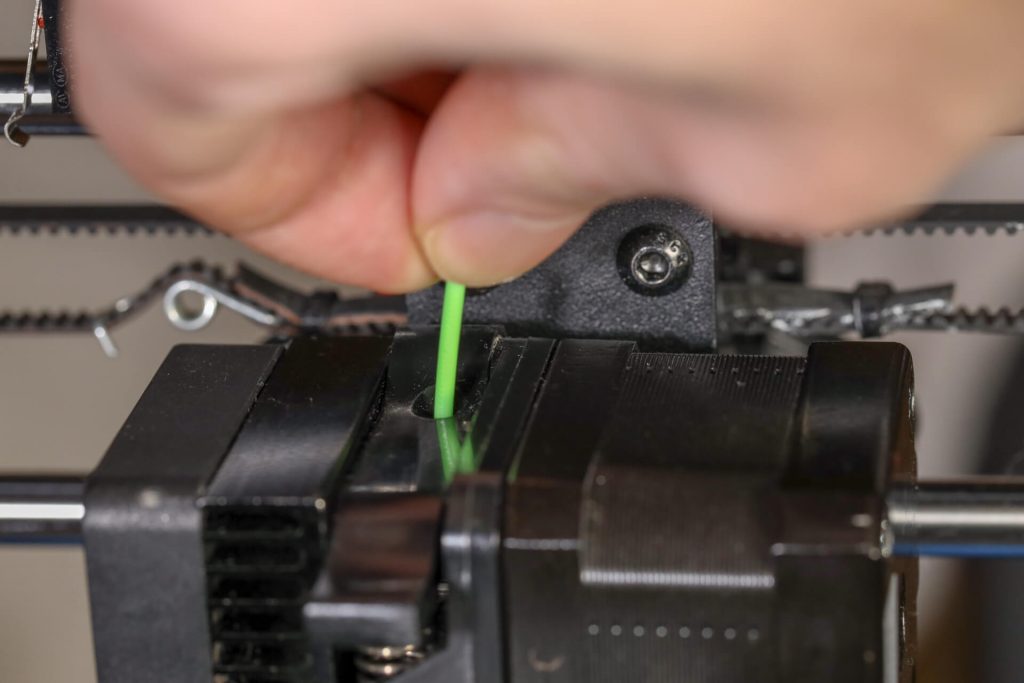 Right-click the part then choose Analyse → New Measurement or pick the ruler icon from the taskbar which allows linear, radius, angular, and wall thickness measurements at specific points.
Advanced Netfabb functions: wall thickness analysis and lattice structures.
Open the Part Repair section by clicking the red Repair icon from the taskbar. If the automated repair script did its job well upon import, the Mesh is Closed and Mesh is Oriented items in the Status tab should be checked in green. In the Actions tab, it is possible to further optimize the file in case intersections pertain to exist. Under Self Intersections, choose Detect and then either opt for Trivial which does a default hole repair, Stitch Triangles, Remove Double Triangles, Remove Degenerate Faces, or Split Off and then Remove the intersections. Wrap Part Surface works similar to voxelisation procedures and leaves only a manifold outer skin. Also, make sure that no noise shells exist under the Shells tab.
Netfabb offers a advanced STL repair capabilities.
When attempting to bridge gaps, Netfabb will rather fill the open holes which require further manual repairs. Tap the Select Surfaces icon on the main toolbar and select the entire hole, then hit Delete. Alternatively, use the Brush Selection tool and use Ctrl + Scrollwheel and the Plus/Minus buttons to alter brush size and selection. With the triangles selected, choose the Remove Selected Triangles icon and manually add missing triangles as well as a few bridging triangles with the Add Triangles button. The Repair → Close all Holes operation will complete the mesh repair task. Finally, we can opt to refine the mesh using the Mesh Edit → Remesh command which recomputes the model based on a Target Edge Length parameter. Check the Maintain Edge option to optimize model integrity around sharp edges.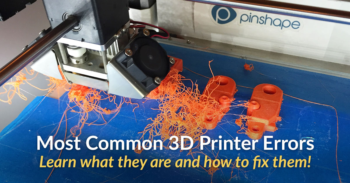
Looking for the right tool to turn your designs into reality? High-resolution stereolithography (SLA) and selective laser sintering (SLS) 3D printers are fast and cost-effective tools to produce high detail models with a smooth surface finish.
Learn more about 3D printers and see the quality firsthand by requesting a free sample part printed on a Formlabs 3D printer.
Learn More About SLA 3D PrintingLearn More About SLS 3D Printing
Repair of 3D printer AnyCubic I3Mega
Technician
doing. I would like to share my experience, firstly - it is interesting for me personally, and secondly, this information can help someone.
Well, let's start.
Anycubic i3 Mega came in for repair with a complaint about the lack of heating of the table. The first thing that surprised me when I saw the printer was the presence of two power plugs. Unfortunately, I did not take a photo, but oh well. The owner of the printer claimed that the printer had already taken the BU. Let's go further. The printer was already partially disassembled, we turn the table over and here it is - the reason. Smoked silicone heating pad 220 V.
We start the printer - there is no temperature indication.
The reason for burning was as follows: The previous owner of the printer decided to leave the original thermistor, which was soldered to the textolite table and stuck out a couple of millimeters instead of using a silicone heating pad thermistor. over time, it peeled off in the center, an air bubble formed, which led to incorrect feedback on the temperature of the heating pad and its overheating! The place of formation of the bubble, by the way, can be determined by the black outline.
By the way, even the heads of the cogs under the table are rusty, due to the fact that their coating has evaporated from overheating.
Definitely a heating pad replacement.
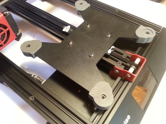
With difficulty, I dug out the old silicone, cleaned the table of glue and soldered all the protruding elements. (Thermistor in the center and two LEDs.) Mega's print area is non-standard, 210x210 mm. Heating element 200x200. I had to leave a 5 mm gap at the edges. Next, we isolate the heater so that the movements of the dry table do not cause excessive temperature disturbances.
I walked around the perimeter with an aluminum high speed to keep the thermal insulation stronger. Native glue seemed not very reliable. Well, that's it, you can put the table in place. It's up to you. We connect the solid state relay. Now it’s normal, to the power supply, and not to a separate plug :) I won’t dwell on the connection diagram, there are a lot of them on the Internet. The relay case was without a protective cover, but the printer was still metal. To avoid shaking, I insulated with a wide electrical tape. It will not float, if suddenly someone has questions)) The normal operating temperature of the TTR is 40-50 degrees. Yes, and the tape is not easy.
I checked the work of the table - everything works. Of course, I would like to adjust the PID, but PIDBEDTEMP is blocked in native firmware. Yes, and not a problem, in general. Temperature fluctuations are amplitude only at the beginning (2 degrees), then they converge to the set value.
The printer has been restored.
What conclusions can be drawn? Installing a silicone heater is a responsible matter. Still, 220V is no joke. The contact surface must be flat and free of grease. Well, be more attentive to the heating elements in general, when smoke / burning smell appears, stop work and find the cause.
Subscribe to the author
Subscribe
Don't want
20
1️⃣ Repair of 3D printers Astana (Nur-Sultan)
Free diagnostics
and departure of the master within an hour!
- Diagnostics
Free - Departure Masters
Free - Warranty
from 365 days - In 1 day
- Experience of masters
more than 10 years - Personal
Manager56
The manager will call you back within 30 seconds
Repair of all kinds of 3D printers
FDM 3D printers
↑
SLA and DLP 3D printers
↑
SLS 3D printers
9002
Popular failures of 3D printers
Will not turn on
Errors on the panel
Excessive noise
002
Printer stops by itself
Extruder clogged
Filament worn off
Nozzle close to platform
show more
Didn't find your breakdown?
Our specialists will consult you free of charge and answer all your questions by phone +7 (778) 096 59 61 or
Repair of 3D printers in Astana
Maintenance of 3D printers requires constant attention of the owner. The technique is characterized by a complex design. Small breakdowns cause printing defects; in advanced situations, the device completely refuses to turn on. Experts recommend immediately disconnecting the equipment from the electrical network, contacting the masters of our service center for help.
Urgent repair of the 3D printer is performed due to the following reasons:
- wear of nodes, bolted connections;
- accumulation of dust, dirt on fan blades, electronic components;
- loosening the normal tension of the belts;
- self-repair attempts;
- the presence of dirt on the guides, running pins;
- lack of regular maintenance;
- incorrect printer setup;
- use of inferior materials;
- electrical problems;
- use of poor quality spare parts;
- manufacturing defect.

First, we perform free diagnostics to identify the source of the problem. We have our own warehouse of spare parts, which are recommended for installation by manufacturers of high-tech equipment.
Our service center offers to order professional repair of 3D printers Astana. The use of modern equipment and the experience of employees helps to cope with malfunctions of varying complexity. You can apply online, by phone. Managers will prompt the current cost of services in Nur-Sultan.
Repair prices for 3D printers
| Cost. | |
| Diagnosis and visit of the master | free |
| Re-flashing and tuning electronics | from 5500 tenge. |
| Electrical repair (wiring replacement) | from 4000 tenge. |
| Mother board replacement | from 5000 tenge. |
| Motor driver replacement and tuning | from 6000 tenge. |
| Replacement/installation of heating table | from 9000 tenge. |
| Stepper motor replacement | from 8000 tenge. |
| Thermistor replacement | from 7000 tenge. |
| Display Replacement/Installation | from 9000 tenge. |
| Replacement of thermal barrier | from 11000 tenge. |
| Nozzle replacement | from 7000 tenge. |
| Thermistor replacement | from 7000 tenge. |
| Heating element replacement | from 7000 tenge. |
| Heating block replacement | from 8000 tenge. |
| Replacement / installation of a new extruder | from 7000 tenge. |
| Prevention (fastening, lubrication) | from 5000 tenge. |
| Mechanical repair | from 8000 tenge. |
| Drive Belt Replacement | from 7000 tenge. |
| Replacing guides | from 8000 tenge. |
| Replacement pulleys | from 7000 tenge. |
| DIY kit assembly | from 10000 tenge. |
show more
Specialists of the 3D printer repair department
ANTON KLUNOV
Repairman
- Experience: 11 years
- Ratings: 127
4.9
SULTAN KOMPYSHEV
Repairman
- Experience: 13 years
- Ratings: 89
4.9
ARSEN IZYKENOV
Head of Department
- Experience: 9 years
- Ratings: 50
4.8
Dastan Baishekeyev
Department manager
- Experience: 13 years
- Ratings: 92
4. 9
ILYA SEVASTYANOV
Repairman
- Experience: 17 years
- Ratings: 87
5.0
Do you want to ask the master a question?
Our experts will be happy to advise you and give recommendations, call +7 (778) 096 59 61 or leave a request
We repair 3D printers of all brands
- Prusa
- wanhao
- Anet
- Creality 3D
- goofoo
- XYZprinting
show more
We are distinguished by three advantages
Low price guarantee
Our prices are based on average market prices because we buy parts directly from manufacturers.
Repair in 1 day or at our expense
Even if after the diagnosis you decide to postpone the repair or refuse it altogether, in any case, the service will be provided free of charge!
Free departure of the master
The specialist will come to the call within 40 minutes after the application is made. Departure will be free even if you refuse to repair!
Own spare parts warehouse
allows you to store a large number of spare parts, which reduces the repair time to a few hours!
No need to go anywhere,
courier will arrive at a convenient time for you!
The on-site service is free of charge, even if after the diagnosis you decide not to repair. All expenses are covered by the company!
Repair stages and pricing
Consultation
You can leave a request or call yourself for a detailed consultation
Meeting with a specialist
The master comes to the place or you yourself come to our service center.
Device diagnostics
A technician will carefully examine your gadget and test it on modern equipment.
Cost negotiation
We will offer several options to solve your problem so that you meet your budget.
1 year warranty
After checking the device by the client, we will issue a warranty card, under the seal of the company.