Dust 3d printer
Solutions for dust and fume extraction in a 3D printing work environment
The popularity of 3D printing, or additive manufacturing, has increased greatly in the past few years. Because of this, it is important to raise awareness of the potential health hazards associated with using the technology. In this blog article, you will learn more about this as well as get an insight into how we provide Swerea IVF with fume and dust extraction solutions for their 3D printing research laboratory.
A rapidly growing industry characterized by innovation
The possibilities of creating customized products with minimal waste and low manufacturing costs have led the 3D printing industry, and the technologies behind it, to grow and develop rapidly. Previously, 3D printers were mostly used for creating smaller quantities of prototyping parts. Today, engineers are 3D printing everything from bone replacements to aircraft and houses, with new possibilities presenting themselves constantly.
Increased awareness of hazardous fumes and combustible dust from 3D printing processes
As more and more companies use 3D printing in their operations, questions have been raised regarding associated health and safety issues. There is a concern about the fumes, dust and odors created during the printing and post processes. With 3D printing being a relatively young industry, scientists have only recently begun to investigate this. And there are studies indicating potential health risks associated with using the technologies. This is the case regardless if you are using the printing process of, for example, material extrusion, binder jetting or powder bed fusion. Study results show that printers emit a significant amount of ultrafine particles (UFPs) and hazardous volatile organic compounds (VOCs). Post processes of gluing, grinding and painting the product have also been shown to generate potentially hazardous pollutants.
Depending on which material and printing process you are working with, the pollutants can be both combustible and cause various health problems if inhaled.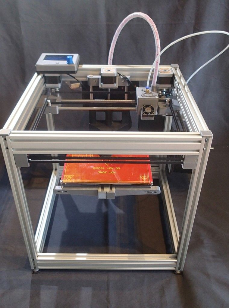 This applies especially in cases of large-scale manufacturing where several machines run simultaneously. Good ventilation and customized fume and dust extraction systems are therefore important to ensure a safe work environment.
Additive Manufacturing Research Laboratory at Swerera IVF
As a provider of clean air solutions, Nederman is participating in the construction of an additive manufacturing research laboratory at Swerea IVF. The Swedish research institute conducts research for industrial renewal and sustainable development. One of their current projects is to set up a production line for additive manufacturing of metallic materials. The aim is to facilitate the industrialization of additive manufacturing by creating a platform for innovative products, materials and processes. In addition, the research laboratory will function as a showroom to display 3D printing applications to interested parties.
Providing extraction solutions for desktop 3D printers and large-scale manufacturing
The Additive Manufacturing Research Laboratory includes desktop 3D printers as well as a system for large-scale manufacturing.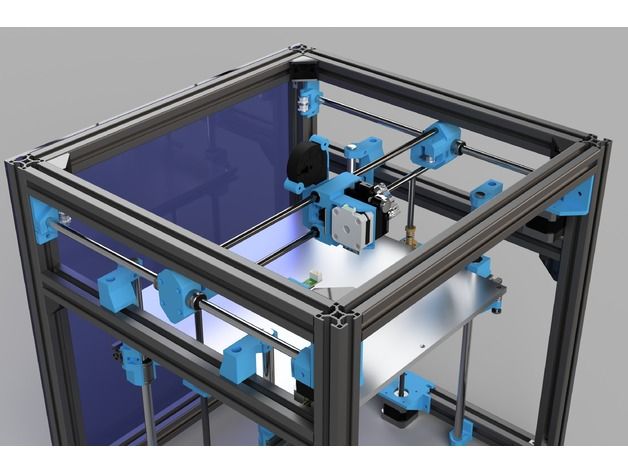 Nederman is providing air filtration and fume extraction solutions for both of these areas. As for now, we have installed benchtop extraction kits for the desktop 3D printers. The kits include a fan, filter, fan speed controller, hoses, table brackets and connectors. Next, we will provide a fume and dust extraction solution for the large-scale manufacturing system. Our solution will extract fumes during the printing process and dust during the machining process. This is done using the same vacuum unit.
In all of the applications described, ultrafine particles, volatile organic compounds, and dust are captured at the source of pollution, before they reach the operator’s breathing zone. The result is a safe and clean work environment where several 3D printers can run simultaneously without causing health risks.
We are excited about being a part of this project together with Swerea, and to see where 3D printing technologies will take the manufacturing industry in the future!
At Nederman, we continually develop our solutions for fume and dust extraction to keep up with the progressions in the market.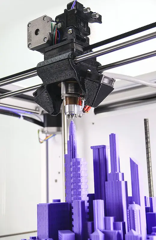 Are you using 3D printing in your workplace? We can help you create a safe and sustainable working environment by recommending suitable equipment and routines. Contact us if you have any questions!
Photo: Swerea IVF.
3D Printing Dust Explosions | Tips
on August 12, 2020 (last updated: April 25, 2022) in Manufacturing, Vacuums
By now, there’s no doubt that you’ve heard and read about 3D printing. Maybe it’s the neighbor down the road making little parts with their system, or you’ve seen a YouTube video on how it works, or perhaps you’ve heard of it in manufacturing rapid prototyping. Well, 3D printing is all of that and more and is one of the fastest-growing areas in global manufacturing.
Additive manufacturing, also known as 3D printing, has been gaining traction over the past decade as a preferred method of part and product production for both hobbyists and industrial manufacturing companies. It is a very cost-effective way to rapidly produce both simple and complex shapes in a prototyping environment. The materials used range from flexible to rigid and from metals to plastics, with new materials created regularly. 3D printing has given inventors and engineers the ability to move through concepts to create a finalized product in a fraction of the time. In years past, prototyping may have included developing expensive wooden models, or handcrafted resin versions. However, 3D printing is proving to be a more cost-effective method for low-volume manufacturing than standard molding practices, and the sky’s the limit in terms of what you can make as there are many shapes you can make on a 3D printer that would not be feasible to make otherwise.
The Three Most Common 3D Printing Methods:
- FDM (Fused Deposition Modeling): melted plastic is extruded through a hot nozzle to create very thin layers that are printed one at a time to create a 3D print.
- SLA (Stereolithography): the part is created by an ultraviolet laser that draws each printed layer into a bath of liquid thermoset resin that solidifies once the laser hits it.
 The build plate recedes further into the liquid bath to create room for the next layer to be printed.
 - SLS (Selective Laser Sintering): the part is created by a high-power laser that sinters either powdered metal or plastics together. The build plate recedes further into the liquid bath to create room for the next layer to be printed.
As promising and safe as this technology sounds, there are still some inherent dangers, with the largest being dust explosions. All 3D printing methods produce dust and other small particles that can become airborne quickly, and remain airborne for some amount of time.
Many materials are combustible that may not seem like it at first, such as metals and some plastics, but when those materials are small enough, it does not take a lot to cause them to ignite. For any sort of combustion to take place, there needs to be a fuel source, an ignition source, and oxygen, all of which are often very present in a manufacturing environment.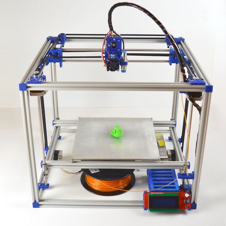 To become explosive, a cloud of dust and some sort of confinement of that dust need to be present. One of the most effective ways to reduce the risk of a dust explosion is using a dust collection system that recirculates the air through filters specifically designed to remove dust. By removing the dust, you have eliminated the fuel source for a dust explosion to take place.
Additionally, and most importantly, is to eliminate the risk of open electrical sparking or exposed electrical current. This is generally accomplished by using specific industrial vacuum systems that remove static and is certified for use with hazardous and explosive materials. In the USA, businesses use the National Electric Code (NEC) designations to identify what systems are approved for what type of flammable materials. It is best to familiarize yourself and your safety personnel with these NEC codes before investigating your specific vacuum options. Goodway Technologies offers a quick review of NEC codes that you can refer to here and a variety of wet and dry industrial vacuums certified for hazardous and flammable material pickup, in electric and air-powered models.
Here are some practical tips for collecting explosive dust powders from your 3d printing operations.
- Identify the right industrial explosion-proof vacuum for your needs. Talk with your safety manager or other industry resources to understand the classification of industrial vacuum you need. This is vital to your safety.
- Explosion-proof vacuums can play a big part in providing a safer environment for additive manufacturing. It is also essential to listen to manufacturer recommendations, especially when concerning safety, and
- Use only certified accessories. Anti-static vacuum accessories designed for certain classifications of industrial vacuums should not be mixed. This can cause sparking and ignition points.
- Follow all OSHA guidelines to create a safe working environment for the employees in the additive manufacturing industry. This includes proper cleaning procedures being followed every day to prevent an accumulation of dust.
To give an example of a dust explosion that has happened in an additive manufacturing facility, we will look at the Powderpart Inc. dust explosion in 2013. This dust explosion resulted in the third-degree burn of an employee, one willful, and nine serious violations of workplace safety standards. This explosion occurred due to several reasons including ignoring manufacturer safety instructions, locating ignition and fuel sources too close together, unsuitable electrical equipment and wiring for a high explosion risk location, lack of employee training in explosion dangers, and a general lack of awareness of the risks at hand. Accidents usually happen when several mistakes are made, so it is essential to make sure that safety standards are being adhered to. Ensure to identify all hazards, train all personnel in the dangers present, and identify danger correctly.
Additive manufacturing has opened a whole new world of possibilities for the manufacturing industry. Still, like all manufacturing, there are risks involved, and it is essential to take the necessary steps to reduce the likelihood of those risks coming to light.
Next Steps:
Check out Goodway Explosion Proof Vacuums.
Use our Vacuum Buying Guide to find the vacuum for your needs.
Need a HEPA Vacuum? See Goodway’s Guide to Selecting a Top Quality HEPA Vacuum
© Goodway Technologies, 2022. All rights reserved. Just Venting is powered by Backbone Media, Inc.
Fine dust and VOC emitted by 3D printers when printing with various filaments (translation) / Sudo Null IT News
Dear forum users, I welcome you again! In the previous translation [1], the bias was made primarily on the data on fine dust emissions when printing with ABS and PLA plastics. This article presents more complete material on research led by the same University of Illinois professor Brent Steffens [2] on the release of fine dust and a whole range of volatile organic substances (VOCs) in the 3D printing process with an expanded range of used types of filament (nine pieces instead of two specified), as well as a range of models of 3D printers (five instead of two). The translation of this article is published with the consent of the author. Thank you for your attention and feedback! nine0003
Abstract
Previous studies have shown that 3D printers can emit significant amounts of fine dust (particles less than 100 nm) as well as some potentially harmful volatile organic compounds (VOCs) during the printing process, and a small amount of circle of filaments and 3D printers. In this article, we determined the composition of fine dust emissions and a small range of volatile compounds when printing with five different affordable 3D printers, using up to nine different types of filament in a hermetically sealed fume hood. The average values of fine dust emission rates were in the range from ~10 8 to ~10 11 h/min (ppm) using all possible combinations of 3D printer model and filament used, and platen temperatures (had the least impact). The analysis showed that among the VOCs released in the highest concentrations, there are gases such as caprolactam when printing with nylon, as well as plastics that imitate wood and brick (in the range of 2-180 μg / min. ), Styrene - ABS and high-impact polystyrene ( 10-110 µg/min.), and finally lactide-PLA plastic (4-5 µg/min.). The results of the analysis of the most concentrated substances in a small office indicate a potential hazard to human health when printing with various plastics in poorly ventilated or not equipped with filtration systems. nine0003
1. Introduction
Nowadays, 3D printers (three-axis printers) are rapidly gaining popularity. This is facilitated by a widely developed sector of low-cost models, mainly designed for the average consumer. The workflow of these additive devices using thermoplastic extrusion with plastics is as follows: an initially hard filament is pushed through a heated extruder, melted and laid in thin layers on an axially moving table. A solid 3D printed model is formed layer by layer as the heated plastic cools and solidifies. It is known that printing in this case can be done with a fairly wide range of filament types: ABS (acrylic-butadiene-styrene), PLA (polylactide resin), PVA (polyvinyl), PC (polycarbonate), hard-pressed PE (HDPE), high-impact PS ( high-impact polystyrene, HIPS), nylon and many other polymers, metals, ceramic mixtures, etc. Depending on the selected filament, the printing temperature of the extruder and the printing table varies, in addition, the choice of the optimal temperature (recommended temperature range) for printing is influenced by recommendations for operation of 3D printer manufacturers when printing with specific materials and the diameter of the print nozzle. Among all plastics, ABS and PLA are considered the most used in printing, other plastics are slightly less popular. nine0003
It is now well known that thermoplastic extrusion of plastics emits both fine dust and gases. However, there is no information about the scale and chemical composition of these precipitates, as well as how their character changes depending on the selected type of filament and 3D printer model. In 2013, we published data on fine dust (particles less than 100 microns in diameter) produced during the printing process of ABS and PLA plastics. These measurements played a major role in the further study of the possible toxic effects of 3D printing volatile products, for example, the poisoning effect of emissions from thermoplastic extrusion in animal experiments was shown, and other sources reported the detrimental effect of emissions from 3D printing on human performance. organs. So far, we are familiar with only one study published by scientists Kim and others, also devoted to the analysis of the composition of fine dust emissions and total concentrations of volatile substances: aldehydes, phthalates, benzene, toluene, ethylbenzene and P-xylene vapors during 3D printing by two closed ABS printers and PLA filaments. The results of this study confirmed twice the emission of fine dust and VOC when printing with the first plastic compared to the second. nine0003
To date, with the exception of data published in these two studies, the known data on the issue of emissions during the printing process is limited. It should be added to this that only a narrow range of 3D printers and types of filaments was analyzed for fine dust and VOC emissions (i.e., only ABS and PLA). Moreover, it is possible that the authors of the research by Kim and others missed some of the volatile compounds released during the 3D printing process, since the group of scientists focused on fixing only substances already known and available for study with a gas mass spectrometer. In addition, we do not have information about the characteristics of the used filaments, as well as the design features of 3D printers (for example, the presence of outlet holes in the design that contributed to the release of volatile substances from the working area to the outside). nine0003
Therefore, in this article we will try to complement the research of the group of Kim and others, expanding the range of investigated substances released during the printing process and the range of printers used to five instead of two, choosing the most popular models of 3D printers today and using up to nine different types filaments when printing standard test patterns in a medium sized fume hood. Based on the data obtained, we also compared the data on the release of fine dust and VOCs depending on the type of filament used and the characteristics of the 3D printer model, as well as the effect of the geometry of the printed object on the concentration of emitted substances. nine0003
2.
 Experimental methods
 2.1. Excretion fixation methods
All measurements were taken inside a 3.6 m 3 stainless steel fume hood with a small metal fan (illustrated in the supporting instructions (Figure S1). All 3D printers were connected to a desktop computer outside the cabinet. Before experiment, the fume hood was pre-equipped with an air filtration unit with a variable operating mode of one hour for eight hours until complete air purification - the starting point of the research.Print tables were also pre-treated with isopropyl alcohol, and if necessary, depending on the model used, 3D- printer and filament type and other adhesives to prepare the print bed for the printing process in accordance with the recommendations of the manufacturers, after which printing of a small model was started.0003
During all stages of the study, except for one, a model was printed, taken from the resource base of the National Institute of Standards and Technology (NISIT), with dimensions of 10×10×1 cm (shown in Figure 1). This model is specially designed for testing and evaluating existing additive technologies, in addition, it has a number of features that allow you to capture dynamic changes in selections during 3D printing due to the complexity of the geometry: thin protrusions, holes and depressions. Also, we repeated the test with the printer when printing with a combination of filaments, printing a cube of size 195 cm 3 , practically no different from the original from the same NISiT resources (taking into account that the geometry of the printed part significantly affects the nature of emissions). The heating period of the nozzle and the print bed took an average of 5-10 minutes depending on the printer model and the filament used, the printing time varied from 2.5 to 4 hours with the variation of the used additive devices, filaments and 3D printed models.
2.2. Air Sample Analysis
Fine dust concentration data was obtained using a TSI Model 3007 Condensing Particle Counter with 1-minute trigger intervals inside a laboratory cabinet on the exhaust side. The particle counter was installed inside an exhaust hose 0.9 m long and 0.6 cm in diameter. This dust counter is capable of measuring total particle concentrations in the range of 0.01-1 µm with an upper limit of particle counting capability of 105 ppm 3 and a maximum flow rate of 0.7 l/min. Measurements were carried out during all stages of the study, starting with the last 45-60 minutes of background concentrations, then 2.5-4 hours of printing models (including the warm-up time of 5-10 minutes of the nozzle and printing table) and the final 3 hours, when dispersion of air compounds until the return to the previous level of background concentrations.
To reiterate, the particle measurement range of the TSI 3007 dust counter is from 0.01 µm to 1 µm, in the same range is the vast majority of detected particles (as shown in the preliminary data section in the Reference Material (Figure S4). Therefore, it can be said with confidence that the obtained data reliably reflect the total concentrations of fine dust, they were later used in the calculation of concentrations. We periodically calibrated the dust counter inside the laboratory cabinet by conducting joint measurements with a dust meter that scans the dynamics of particle sizes, TSI Model 3910 which has been adjusted by the factory manufacturer. We had no doubts about the accuracy of the last device, but it was not possible to use it throughout all stages. Therefore, it was necessary to resort to the calibration of the dust meter through regression with polynomial coefficients, using data from these few stages of joint measurement by both devices. The synchronism of obtaining data on the total number and concentrations of particles for a long time was almost not disturbed in the range of recommended throughput values, taking into account the manufacturer's recommendations (up to 105 h/cm 3 ), but subsequently decreased exponentially for particles larger than the size range of ultrafine dust, which is typical for such equipment. This had to be taken into account due to several large jumps in total concentrations, exceeding the throughput of 105 h/cm 3 in a fume hood.
Air sampling was also carried out inside the cabinet and during VWO analysis using Tenax-GR sorbent tubes over two periods: the first ~45 minutes before printing (i.e. with the printer turned off in the chemistry cabinet) and the second during the same length of printing time until the equilibrium state of the air is established. We used the concentration difference between these two steps to record values for the ten most concentrated gases individually and collectively with the TSI-Q-Trak Model 7575 Air Quality Monitor coupled with a Model 9 Photoionizing Sample Detector.82. This was necessary for several reasons: firstly, to ensure that the mass balance equation for the total concentrations of VOCs during air sampling was valid, secondly, to ensure that the gas mixture had reached equilibrium after two hours from the start of printing, and finally that the function of total allocations has the form of a constant (reflected in Figure S3). Therefore, we consider the process of taking air samples for subsequent BWO analysis in the last ~45 minutes of printing of each object as reasonable for the equilibrium state. nine0003
The technology for sampling and analysis of adsorbent tubes used in these studies, with some modifications, is based on the TO-17 method developed by the US Environmental Protection Agency. The adsorbent tubes were placed in the small outlet of a fume hood, connected to a low power Buck VSS-1 air pump at an operating speed of ~20 ml/min. Air flow rates were measured at the end of each study period using the Gilian Gilibrator 2 and then used to obtain the total volume pumped. Subsequently, all tubes were immersed in freezers for onward transport to the University of Texas at Austin, where they were analyzed by thermal desorption followed by gas chromatography with 4-bromofluorobenzene as an internal standard and electron mass spectroscopy. Subsequently, the composition and concentrations of VOCs were determined based on the base of volatile compounds of NISiT, as well as the mass of absorbed gases based on the reaction with an internal standard with a relative response factor of 1. Under these conditions, the relative response factor in the interval is usually approximately from 0.75 to 1.25 for the majority of possible BWOs, therefore, when determining the calculation errors, we took 25% as an approximation coefficient. For some gases, this value may not exist, but this only indicates the correctness of the calculations of VOC concentrations. nine0003
We also measured VOC concentrations outside the fume hood during the entire printing process to ensure that no gases could escape into the fume hood. For this, adsorbent tubes were also used, but this time without connection to air pumps. Finally, we measured temperature and relative humidity, using the Onset HOBO U12, at 1-minute intervals, as well as the ventilation coefficient with carbon dioxide as the trace gas (described in more detail in the Reference Information) throughout all phases of the study. The last gas was vented from a small gas cylinder into a fume hood at the beginning of each sampling period, the concentrations of the gas already dispersed recorded by a PP Systems SA-5 carbon dioxide monitor paired with the previously mentioned Onset HOBO U12 also at 1 minute intervals. nine0003
2.3. Fixation of fine dust emissions
Due to the significant scatter of fine dust concentrations, we initially decided to smooth the graphs of the obtained functions in the MATLAB 2015a software package (reflected in the Supplementary Material). We subsequently used these smoothed functions to determine the time-based concentrations for each combination of printer and filament type in the mass balance equation for the total dust concentrations measured inside a chemical fume hood (shown in Equation 1 and Supplementary Material). nine0003
, where:
E UFP is the dependence of the concentration of fine dust from time to minute,
V - the volume of the exhaust cabinet M
3 9000,∆t - the time of the measurement step (interval in the interval in 1 minute),
L UFP - total concentration loss per minute,
C UFP,bg - average background concentrations of fine dust inside the fume hood before measurements,
L UFP - was taken as a logarithmic regression with the values of the first 60 minutes of the final stage after the completion of printing, which is also shown in the Reference Information. It should be noted that when compiling Equation 1, many assumptions were made that could lead to significant errors in determining the concentrations of fine dust, firstly, the dynamics of particle size and coagulation were ignored, and secondly, the loss of particle concentrations was assumed to be constant. The most potential impacts due to these assumptions have been detailed in the Background Paper. Also, we calculated the error in calculating the time dependence of concentrations - about 45% (reflected in the Reference Material). nine0003
Time-based fine dust concentrations were also used to calculate the total concentrations of fine dust emitted during the printing process per weight of filament used, as shown in Equation 2:
where:
E particles emitted during printing based on the mass of used filament,
N - total number of time intervals (in minutes),
m object is the weight of the used filament (i. e. the weight of the printed model).
Notes for Table 1. a For all experiments except for one, we printed a model taken from NISiT resources. b Studies with repetition of VOC measurements. c Repeated measurements of fine dust. d Studies with additional measurements outside the fume hood. e Research with the replacement of the printed model from the NISiT resource base by ~195 cm 3 cube.
2.4. VOC concentrations
As a result of gas chromatography and electron mass spectroscopy, carried out in the period before the start of printing and the last ~45 minutes inside the fume hood, concentrations of up to fifty different VOCs were determined. Equation 3, by which the concentrations of all the indicated VOCs were determined, contains several assumptions. Firstly, ventilation was only a mechanism for removing the particles under study, secondly, the concentrations of the ten most concentrated emitted VOCs outside the fume hood were so insignificant (experimentally verified) that they were further neglected, thirdly, at the final stage of sampling VOC concentrations returned to background levels. More details about these assumptions can be found in the Reference Information. nine0003
, where:
E VOC,i is the constant emission rate (µg/min),
C VOC,i,print during the last ~45 minutes of printing (µg/m 3 ),
C VOC,i,bg — individual background VOC concentrations inside the fume hood before printing (µg/m3). We have calculated that the errors in these calculations are approximately 36%, as described in the Reference Information. nine0003
Total emissions of all ten most concentrated VOCs ( ΣVOC) were obtained by adding all individual VOC values inside the fume hood over the last ~45 minutes of printing. We decided to limit the number of the most concentrated gases to exactly ten, since the subsequent VOCs in the table make up a very insignificant fraction of the total concentration of gases ΣVOC i . In addition, the total discharge rate per gram of filament used in printing was also calculated, which is reflected in Equation 4:
, where:
E σVOC - Total discharge speeds of the ten most concentrated gases,
ė σvoc - the total discharge rate per grams of the reference reference.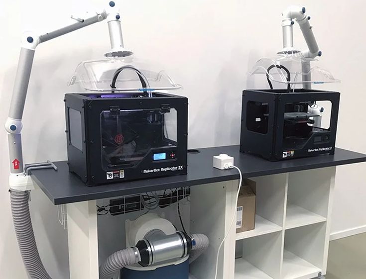
2.5. Description of printers and filaments used
We analyzed fine dust and VOC emissions data on sixteen different combinations of five popular home printers and nine different commonly used filaments. Among the first five models: FlashForge Creator with dual extruder, compatible with ABS and PLA (both plastics were used in research), Dremel 3D Idea Builder, only compatible with PLA, XYZprinting da Vinci 1.0, only compatible with ABS, MakerBot Replicator 2X, compatible only with ABS and LulzBot, in combination with the most common filaments ABS, PLA, HIPS, translucent nylon, Laybrick (imitation sandstone), Laywood (imitation wood composite), transparent polycarbonate, translucent thermoplastic nylon-based polyamide (PCTPE) and transparent polyester resin (T-Glase). Three of these printers, Dremel, XYZprinting, and MakerBot, are open type printers, while FlashForge and LulzBot are hermetically sealed. Of course, this list of printers is far from exhaustive, but it still allows you to cover a fairly large segment of today's most popular models of 3D printers, taking into account all sorts of existing distinguishing characteristics, such as the type of filament used, the temperature of the heated nozzle and print bed during printing, the presence or lack of additional structural elements. Table 1 summarizes all the experiments performed. nine0003
15 out of 16 combinations of printers and filament types were printed by NISiT test model, with the exception of one (LuilzBot-ABS) - a cube model. In addition, the MakerBot that printed ABS was also used twice: the first time when printing with an additional restrictive element provided by the manufacturer, and the second time without. We also presented individual data on VOC and fine dust emissions for these four combinations in order to assess the discrepancy between the data. nine0003
3. Results and conclusions
Figure 2. (a) The function of the obtained sample, as well as the smoothed function of fine dust concentrations and (b) time-based fine dust concentrations when printing LuizBot Mini 3D printer ABSOM3.1. Fine Dust Emissions
Figure 2a illustrates the graph of fine dust concentration over time when printing with LuizBot Mini ABS, as well as the sum function of fine dust concentrations. On the left image, the thick line shows the moment of warming up the printers before printing, which we also considered as one of the research stages. Figure 2b shows the time function of fine dust concentrations described by Equation 1. Pictures S6-S23 show similar time dependences of fine dust concentrations and dust levels for all sixteen combinations tested. nine0003
The results in Figure 2a almost coincide with most of the experiments, in which the concentrations of fine dust usually begin to rise rapidly immediately after the start of printing and persist for 10–20 minutes, immediately after which they fall to the bottom mark, not lower than the values of background concentrations. In several tests with other combinations of printers and filament types, fine dust concentrations again reached their peak around the end of the print period, due to the formation of ridges on the printed model. On the other hand, the dynamics of fine dust concentrations directly depends on the 3D printer model used, the type of filament, the geometry of the printed object, the temperature of the nozzle and the printing table, and the printing time. In the two scenarios considered (depicted in Figure 2a), fine dust concentrations approximately reach the equilibration level by the end of the printing period. We used data from these periods to verify the validity of the mass balance equation for fine dust concentrations described in the Reference Information for describing time-based experimental values of fine dust concentrations. The values obtained by both methods do not diverge during the described periods of research, on the basis of which it can be concluded that the dynamic mass equation for determining the concentrations of emissions is correct in this case. nine0003
Figure 3 illustrates the time dependence of fine dust concentrations for all sixteen combinations of printers and filaments, divided into groups: (I) ABS, (II) PLA, (III) other filaments.
Fine dust concentrations are highly dependent on operating conditions and 3D printer model, filament used, nozzle and platen print temperatures, and print time. The highest concentrations occur when printing ABS plastics with average values ranging from ~2∙10 10 to 9∙10 10 h/min. among all ABS printers, regardless of the presence of additional designs. The lowest values occur with the three 3D printers using PLA plastics due to factory specifications and 3D printer model, with average values being 10 8 h/min. This is noticeably lower than in our previous study, where there were slightly different experimental conditions, including a 3D printer model. Record average values of fine dust concentrations were recorded on the LuIzBot Mini printer when printing with polycarbonate (~4∙10 10 hrs/min), next in decreasing order PCTPE (~2∙10 10 hrs/min), T-Glase (~5∙10 9 hrs/min), HIPS ( ~4∙10 9 hrs/min), Nylon (~2 10 8 hrs/min), Laywood (~8 10 7 hrs/min) and Laybrick (~6 ∙10 7 h/min).
Replacement of the NISiT research model with the ABS cube model with LuIzBot plastic printer did not particularly affect the dynamics of fine dust concentrations and, accordingly, the curve function of concentrations versus time. It is noteworthy that the presence of an additional design only slightly reduced the concentrations of fine dust when printing the MakerBot - ABS combination, the average values decreased by ~35% (also this discrepancy along with the error). Larger discrepancies were not considered, if only because the 3D printer was not hermetically sealed during the studies. During additional research data on how the geometry of the printed model and the lack of tightness can affect the concentrations of fine dust from the 3D model, no other definite conclusions are able to describe the presented data set. Finally, the data obtained during additional studies (Figure 6, 7, 17, 18) with and without structural elements also clearly demonstrate the significant influence of this factor: the average concentrations were 57% versus 48%, respectively. nine0003 Picture 3. Total concentrations of fine dust for 16 combinations of 3D printers and filament types. Each dot represents the data in one minute intervals, and the combination represents the entire print period (usually between 2.
 5 and 4 hours). Bold lines imply 25 and 75 percent values (50 percent median). The thin lines are the upper and lower adjacent values, the circles stand out sharply.
3.2. VOC concentrations
Figure 4 shows the concentrations of VOCs studied individually as well as in total, using data from 16 different combinations of printers and filament types used. Only the three gases with the highest concentrations were targeted for VOC concentrations in each test carried out, the remaining ten VOCs were listed as Remaining VOCs. The total value of these Remaining VOCs is characterized by ΣVOC . In addition, these ten VOCs with the highest concentrations during printing were compiled for all sixteen combinations inside the fume hood, as well as 4 additional studies (the results are shown in Table S2), Table S3 reflects the data outside the fume hood.
The choice of the type of filament affected the concentrations and nature of the emitted gases, while the change in the design features and model of the 3D printer had a greater impact on the total concentrations of emissions when using the same filament. Total concentrations ( E ΣVOC ) ranged from ~3 µg/min. for polycarbonate up to 200 µg/min. for the same nylon (both values are fixed when printed by LuIzBot). The three most concentrated gases accounted for up to 70% of the total VOC emissions E ΣVOC in all studies. For most combinations of printers and filament types, these gases were in overwhelming quantities compared to the rest of the VOCs.
The most key gas among all VOCs released in all six combinations with ABS and only one with HIPS was styrene. The rate of release of this gas during printing with the specified filaments varied from ~12 to ~113 μg/min, depending on the model of the 3D printer used and its design features. It is noteworthy that both the lowest and highest concentrations were obtained when printing with a non-hermetically sealed design (XYZprinting and MakerBot). Both the concentrations of styrene separately and the total concentration values obtained in this case turned out to be somewhat less than when printing with the combination LuIzBot - ABS of the cube model compared to the NISiT model, however, it is noticeably higher than when printing with the MakerBot - ABS combination with additional structural elements, in contrast to the data, printed without them. nine0003
First of all, among all the VOCs released when printing with nylon, PCTPE, Laybrick and Laywood, caprolactam should be highlighted. All plastics were used in conjunction with a LuIzBot 3D printer. All of the listed filaments during the printing process became serious sources of VOCs (shown in Figure 4b), among which the highest release rate for caprolactam reaches 180 µg/min. when printed with nylon. Caprolactam was also released during the printing process with polycarbonate and T-Glase filaments on the LuIzBot, although in much smaller quantities (Figure 4a). Finally, lactide (3,6-dimethyl-1,4-dioxane-2,5-dione) turned out to be the most concentrated gas released during PLA printing, albeit in relatively lower concentrations - from 4 to 5 µg/min. when printed with three different models of PLA 3D printers. We are convinced of the strong dependence of the spectrum of VOCs emitted on the type of filament used for most of the tests carried out and even for tests where printing adhesive was used. Since the main derivatives of the latter were also measured separately (propylene glycol and glycerol, as shown in Table S2), only one combination was found (shown in Figure 4). nine0003 Picture 4. Emission values for the three most concentrated VOCs, or less, that is, the remaining ten gases when printed in sixteen different combinations. For visual clarity, the data are divided into two groups: (a) weak sources with a release rate of up to 40 µg/min. and (b) strong - more than 40 µg/min. When compiling the tables, errors were not taken into account, for each gas it amounted to ~36%, which is reflected in the Reference Information.
3.3. Nozzle and Platen Heat Effect
In the next step, we examined the data on fine emissions and total VOC emissions as a function of nozzle and platen temperature (Figure 5). The data were divided into three groups according to the temperature of the printing bed: less than 45 ֯С, in the range of 60–65 ֯С and in the range of 100–110 ֯С, a graph was also built depending on the temperature of the nozzle (in the range of 190–270 ֯С, as illustrated in Table 1).
An increase in nozzle temperature had almost no effect on the concentrations of fine dust released during printing in the study of the data of the first and last groups. However, the opposite result was observed at medium table temperatures, when a significant increase in fine dust concentrations was recorded. In a separate study, the change in the temperature of the printing bed (without changing the temperature of the nozzle) showed a significant increase in the concentrations of fine dust. Most combinations of 3D printers and filaments in the upper temperature range had large concentrations of fine dust, while lower concentrations were observed in the lower temperature range. On the other hand, no relationship was found between total VOC concentrations and changes in platen or nozzle temperatures. The study of other combinations of 3D printers and types of filament may give a different result, but here we are talking about a small sample. nine0003 Picture 5. Influence of printing temperatures of the nozzle and printing table on the concentrations of fine dust and VOC.
3.4. Dependencies between the total concentrations of fine dust VOC per unit mass of filament
Figure 6 illustrates the data of the total concentrations of fine dust (reflected in Equation 2) and VOC (reflected in Equation 4) per unit mass of filament during printing for all sixteen combinations of 3D printers and types of filament.
The total concentrations of fine dust per unit mass of the filament vary in the range from ~2∙10 8 U/g with LuizBot - Laybrick combination up to ~2∙10 11 for most ABS printers. The total concentrations of VOCs per unit mass of filament range from ~6 µg/g for the LuizBot-polycarbonate combination to 800 µg/g for nylon printing with the same 3D printer model. Moreover, when printing with ABS, PCTPE and HIPS filaments, the highest values for the total concentrations per unit mass of both fine dust and VOC appeared, while when printing with PLA plastic, there were relatively low values for both the first and second concentrations. It is also noteworthy that printing with both T-Glase and polycarbonate (both filaments were used in conjunction with LuizBot) gave low VOC emissions, but high fine dust emissions. In contrast, printing with Laywood and Laybrick filaments (also used in conjunction with LuizBot) gave high VOC releases, but low fine dust releases. Similar results should probably also not be extended to other combinations of 3D printers and filament types not considered in these studies. nine0003 Picture 6. Fine dust concentrations per gram of filament
3.5. Effects of human exposure to printing products
Published data on concentrations of fine dust and individual VOCs carry considerable weight in the study of the effects of products released during the printing process on the human body. For example, styrene, according to the International Agency for Research on Cancer (IRCA), is a carcinogen (IRCA group 2B), turned out to be the most concentrated VOC in 3D printing by all types of ABS and one type of HIPS. Caprolactam, also detected in large quantities when printed with nylon, PCTPE, Laybrick, and Laywood, is not considered a human carcinogen, however, the California Environmental Hazards Authority defines the gas as a source of acute, sustained (over eight hours) irritation at extreme permissible concentrations 50.7 μg / m 3 and 2.2 µg/m 3 single and daily, respectively. For polylactide resin vapors, the most concentrated gas among all products emitted during 3D printing of PLA with plastic, there was no information confirming its harmfulness.
In order to draw a more or less clear line when analyzing the allowable concentrations, as well as the possible potential harm caused by volatile products in the process of 3D printing in a small enclosed space, in the study we used data from the conducted experiments on the concentrations of fine dust and VOCs. Of course, our attempt cannot be called a complete detailing of the impact of a whole range of harmful substances released during the printing process, rather, it is a preliminary review of the most concentrated volatile substances that have an impact on the human body. It is also worth taking into account the errors in obtaining these concentrations, which may have led to an overestimation of the concentrations of fine dust and VOC under various experimental conditions. nine0003
In this study, the 3D printer ran smoothly in a well-ventilated 45 m 3 office space (i.e., the same office used in previous studies by Steffens et al., with fine dust concentrations of ~10 11 h/min and 183 µg/min for caprolactam, 113 µg/min for styrene and 5 µg/min for lactide, assuming an air mass mixing level of 1 h -1 without any loss for of the three listed gases (probably a conservative estimate), as well as the rate of fine dust settling in 1.3 h. -1 ). Taking these assumptions into account, the background concentrations for all studied steel components are ~58000 cm -3 for fine dust, ~244 µg/m 3 for caprolactam, ~150 µg/m 3 for styrene, and ~6 µg /m 3 - for lactide.
The reported concentrations of caprolactam (244 µg/m 3 ) exceed all three acceptable limits, according to the California Research Center, even with significant errors (caused by the previously listed assumptions) when printing with nylon and other nylon-containing plastics, which is fraught with unpleasant consequences for health (in particular, for people with reduced immunity). It should be noted that exceeding the norms of caprolactam concentration can cause irritation of the mucous membranes of the eyes and respiratory tract, and can also adversely affect the nervous system (according to the Center for Disease Control and Prevention). nine0003
Calculated concentrations of styrene (~150 µg/m 3 ) under the same conditions are approximately twenty times higher than background concentrations in offices (according to studies conducted by the Environmental Protection Agency) and more than twenty times greater than average concentrations in the home environment. There are also articles reporting that such an excess of styrene concentrations is fraught with poor health. For example, high levels of styrene can increase the risk of cancer (considered in one study as one of the natural factors in the development of cancer), and is also a major source of lung disease in infants (i.e., exceeding as little as 2 µg/m 3 ).
We are not aware of maximum allowable fine dust limits, however note that concentrations of ~58000 cm -3 would be approximately ten times the background dust concentrations in an office building, laboratories and schools. Also, these values are slightly higher than average dust concentrations in houses. However, this is still less than in other similar environments.
Given all the data given, we can make certain recommendations. First, it is necessary to supplement the presented data on fine dust concentrations and individual gas concentrations for their more accurate assessment, studies should take into account the proximity effect. Second, 3D printing filament manufacturers should focus on developing or refining existing 3D printing filaments that release as few harmful products as possible during the printing process. Thirdly, in view of the possible lack of such plastics at the moment, 3D printer manufacturers should pay attention to the tightness of 3D printer cases or start introducing air filtration systems. Until emissions issues are resolved, we strongly discourage the use of 3D printers in poorly ventilated areas or without the use of air filtration systems. This is partly true for styrene/nylon-containing plastics as well, based on studies performed on a sample of sixteen combinations of filament types and 3D printers. nine0003
Link to referenced literature [3].
Thank you all for your feedback and comments!
Moon dust 3D printer
AstronauticsTechnology
09/08/2019
3,831 2 min read
Building a moon base is a real challenge. To avoid the transfer of heavy materials from the earth, scientists are developing the possibility of using lunar dust in special 3D printers. They should be able to print building blocks directly on the spot - the so-called additive manufacturing. nine0003
Ross Friel, senior lecturer at Halmstad University, leads a team of researchers working on autonomous additive manufacturing (also called 3D printing) that can be used on the moon.
Earth's resources are limited, so our continued existence requires that we look beyond our planet. There are endless resources in space. To be able to explore, both inside and outside, our solar system, a lunar base is needed that can serve as a "springboard" for space travel. According to Ross Friel, it is economically and technically advantageous to use the Moon as a launch pad because of its low gravity, extremely thin atmosphere and clear skies, and the ability to use hydrogen and oxygen from lunar ice for rocket fuel. nine0003
The task of building a moon base
Building a moon base is not an easy task. The building material must withstand and protect people and scientific instruments from harmful cosmic radiation and meteoroids. It is impossible to transport heavy concrete from the Earth to the Moon - it is too expensive. Therefore, being able to use materials already on the Moon to create building blocks and other useful components such as spare parts could be a better solution.
Lunar dust, i.e. fine gravel on the Moon called lunar regolith, is a natural ceramic material - much like volcanic ash on Earth. In our study, we used material from the earth with properties similar to moon dust. Real dust is hard to come by, says Ross Friel.
3D printer on the moon
By melting moon-like material from the earth, various types of structures can be printed on a specially designed 3D printer, such as cubes, filter elements and screws, directly on the surface of the moon. nine0003 By melting material from the earth, which has properties similar to moon dust, various types of textures can be printed using a specially designed 3D printer.