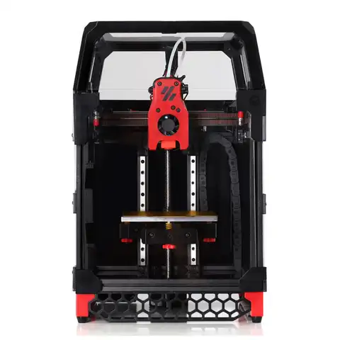
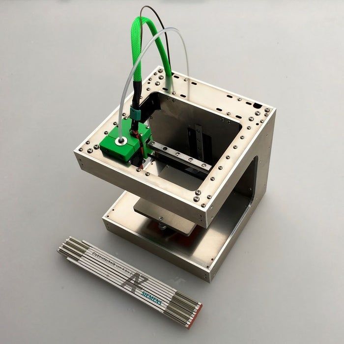
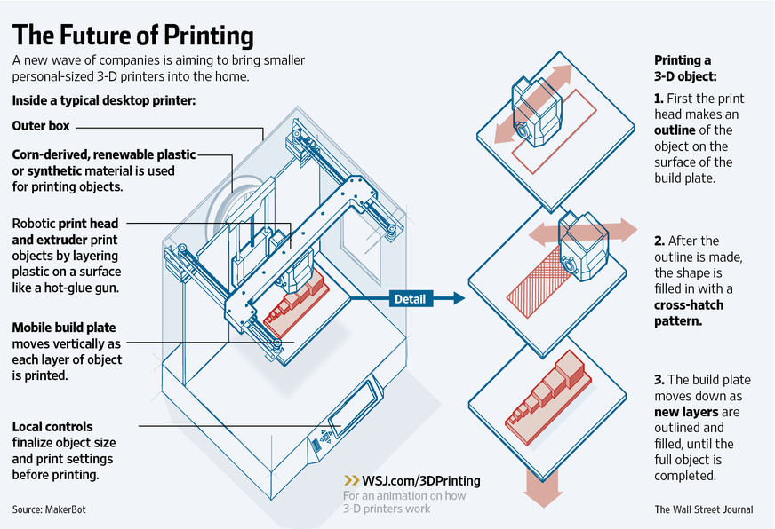
Diagram of 3d printer
3D Printing, Tactiles and Haptics
New technologies for creating tactiles and tactile experiences offer revolutionary ways of conveying spatial information. The work described below represents the DIAGRAM Center’s ongoing exploration of these technologies, including 3D printing and haptics.
3D Printing in Schools | Printing of Braille with 3D printers | SVG and 3D Printing | 3D Printed Teaching Aids
3D Printing National Forum | General Info on 3D Printing | Decision Tree
Tactile Graphics Project | Tactile Graphics Webinar | Imageshare | Haptics
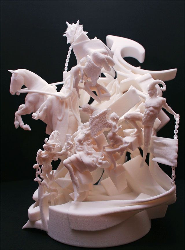
3D models add another dimension of depth to traditional images and open doors for multimodal learning. With revolutionary implications for education, medicine, and more, 3D printing offers a low-cost alternative to creating 3D models that increases opportunities for customization and experimentation. The DIAGRAM Center is exploring 3D printing technology as a way to increase access to curriculum and learning. For students, 3D-printed models can offer better ways of understanding spatial concepts for things that would otherwise be too large, too small, too valuable/rare, or too dangerous to hand to a student. They can be customized, created by non-specialists in accessibility, and shared with all students in a classroom.
Printing of Braille with 3D printers
The introduction of 3D printers in education has created a new opportunity for people to create tactile materials for students who are blind. This document seeks to inform object creators about the best way to add braille to 3D objects.
Based on testing with braille reading users and many different types of printers (Makerbot, MakerGear, TypeA, Ultimaker, and more) we found that ‘vertical braille’ is the best method of printing braille with a 3D printer (see below). Testing was conducted by the Lighthouse for the Blind and Visually Impaired in San Francisco, Texas School for the Blind and Visually Impaired, DIAGRAM Symposium on 3D Printing.
Download Word Version of Document
3D Printing for Accessible Materials in Schools
In 2013, researcher and TVI (Teacher of the Visually Impaired), Yue-Ting Siu (UC Berkeley & San Francisco State University) conducted a one-year research project about 3D printing in education. The main advantages of using 3D printing are: bringing imagined creations to life, ability to customize devices, enhancing the learning of all students in a classroom, and use of the technology by anyone to create an accessible environment. While there are still some challenges, Ting provided some recommendations that include:
- Collaboration between technology, computer programming, general education teachers, and community supports
- Simplify implementation of 3D printing to the acquisition and maintenance of a 3D printer as the technology gets more affordable and usable
- Cultivate open access repositories that offer curated selections of files for easy download and printing as aligned with academic curricula
- Provide training to promote understanding of 3D printing’s capabilities and how it fits into the larger set of tools for providing accessible materials for students with visual impairments.
Read the full report here (Word document): 3D Printing for Accessible Materials in Schools (final version). See also a closed-caption recording of Ting’s DIAGRAM webinar on this topic, along with handouts and a written summary of the Q & A for the webinar: 3D Printing for Accessible Educational Materials.
SVG and 3D Printing Report
In the DIAGRAM-sponsored report “Assessments of Raster-to-Vector (SVG) Conversion software and 3D Printers for Tactile Graphics” National Braille Press assesses SVG software to find a version that is affordable, and easy to use for publishers and individual content providers. Beyond the DIAGRAM Center’s interest in SVGs for publishers, SVGs also provide a number of digital conversion options for tactile graphics like 3D printed objects, when description alone is inadequate. 3D printers may provide one method for these solutions that can provide perfect proportioning, detailed resolution, and reduce the labor time required compared to the collage methods of creating tactile graphics, especially with complex images.
Download PDF Version of Report
Download Word Version of Report
Stanford Student Research Paper: “3D-Printed Teaching Aids for Students with Visual Impairments”
In the spring of 2014, three Stanford University undergraduates became interested in the work Benetech and DIAGRAM were doing to support accessibility in STEM for students with visual impairments.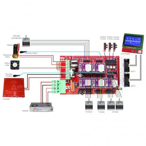 They set out to first determine what instruments already existed for these students and evaluate the need for 3D printed education tools. They then worked to address the lack of learning aids by designing and printing a variety of objects to be used in STEM classrooms. The results of their work indicated that 3D printed models fill a hole in available learning aids for visually impaired students, but determined it wasn’t feasible for them to design and print individual objects. They hope to work with Benetech and other members of the assistive technology community to build a repository of 3D designs that can be standardized for large scale general use in classrooms.
Download Word Doc
3D Printing National Forum
In October 2014, with numerous DIAGRAM community members joining, Benetech kicked off a 3D Printing for Accessible Education grant from the Institute of Museum and Library Sciences. Our deliverables include a National Forum to discuss topics and issues around 3D printing in education, a quick-start guide for 3D printing and a collection of STEM objects available for educators. We hope that our work will contribute to the field of accessible tactile objects for education. On June 17-19, 2015, we conducted a forum that brought together museums, libraries, educators, end users, technologists, and publishers to discuss the implications of 3D printing technology for education. Hear the presentation from the post-forum recap webinar (or download the slides from the recap webinar here: 3D Forum Recap Webinar 8415 (NN)) to learn more about the outcomes of the forum.
3D printed objects
quick-start guide for accessible printing (online PDF)
quick-start guide for accessible printing (word document)
For more general information about 3D printing and education see:
- Exciting Developments in Uses of 3D Printing in Education
- 3D Printing Industry (Education)
- 3D Printers in the Classroom
- 3D printers in schools: uses in the curriculum
- 3D printing in schools: The next industrial revolution?
- Horizon Report
For more information about any of the DIAGRAM 3D printing projects or to contribute to our growing collection of research on 3D printing for education, please email 3D(at)benetech(dot)org.
Decision Tree
Developed by Touch Graphics, Inc., the Decision Tree (report in Word) is a tool for choosing which print images need tactiles and which need descriptions. A digital decision tree allows the creation of tools that will expedite the work of making textbooks accessible by allowing non-specialists to make good decisions about which images need what kind of treatment to make them accessible. The tool was found to be a successful method for novices to categorize images (mean 66% correct). Future improvements to the tool’s success will come with better understanding and agreement among experts as to whether certain images need verbal or tactile treatment. The open-source image sorting tool was built using Lime Survey. The related survey questions and the xml are freely available. A flow chart is also available (Word version here) that shows how the decision process was captured in the sorting rubric.
Tactile Graphics with a Voice
The Tactile Graphics Project at the University of Washington has created the TGV (Tactile Graphics with a Voice), a QR-code reading app that allows text within images to be read and voiced by a mobile device such as an iPhone or Android phone. For those who are interested in creating tactile graphics that include QR-codes for embedded text in images, there is a revised Tactile Graphics Assistant Manual (PDF version here) that includes information about how to include QR-codes. The TGV Design Document is available for boththe iOS (PDF version) and for the Android (PDF version). The open source code is available for both the iOS version and the Android version of TGV as well. See the published paper about this work, which won Best Student Paper at the October 2014 ACM SIGACCESS conference on computers and accessibility.
Webinar: Tactile Graphics with a Voice
Imageshare
Developed by the DIAGRAM Center, Imageshare is a shared, open source platform for educators and consumers to explore and find alternative resources (modalities) related to key STEM concepts. As more accessible alternatives for images, such as tactile graphics and 3D object are produced, the benefit of having a centralized location where contributors and consumers can reference and discover accessible content also increases. Imageshare is that centralized collection that’s curated for accessibility. It not only eliminates redundancies within and across organizations, but also allows sharing of costly, time-intensive, and limited resources involved in the production of alternative content.
Prior to the adoption of the current name, “Imageshare,” this platform was also referred to as the Registry-Repository of Accessible Images (RRAI) and the Accessible Image Repository-Registry (AIRR).
Try Imageshare (alpha)!
Integrating Haptic Feedback for Image-based STEM Content within HTML and eTextBooks
-Mark Hakkinen, ETS
Summary:
Haptic technology, already present on some tablets and smart phones, is emerging as an innovative way to augment visual information with effects such as vibration or “feelable” textures. The implications for accessibility are exciting and this project explored using vibrotactile feedback to augment visual information in EPUB and HTML content. A sample EPUB with haptic enabled SVG shapes was developed and is available for download. Additionally, instructions and source code for adding haptic effects to EPUB and HTML content is provided. Finally usability issues with haptic interfaces are discussed along with the results from a usability study with students with visual impairments.
Introduction:
Consumer tablet devices, such as the Apple iPad and Google Android products, are making significant inroads in education as a platform for delivering eBooks, instructional material, and assessments. Accessibility of the devices, and the content presented using them is an important consideration, especially for students with visual impairments, where access to graphical and spatially presented information essential to the study of science, technology, engineering, and mathematics (STEM) can pose significant challenges.
A new class of technology – tablet-based haptics – may enable an effective mechanism for presenting graphical information to students with visual impairments.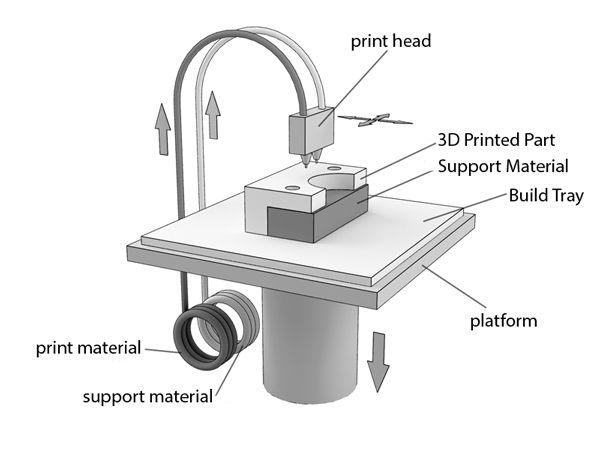 As tablets with haptic capability increase their foothold in the classroom, and in the hands of students at school (and home), there is the potential for significant advances in how students with visual impairments are enabled to independently interact with STEM content. This DIAGRAM Center funded research project examines the use of haptic feedback as a means to provide access to graphical information in HTML and EPUB, using widely available vibrotactile feedback. Sample content, source code, and a discussion of usability issues is included.
Learn More About Haptics
3D Printing Evolution Functional Block Diagram
This 3D Printing Evolution Functional Block Diagram shows the process flow of 3D printing in the X direction and the evolution of the functional blocks in the Y direction.
Extruder
Dual/Multi extruder
The first improvement to the extruder, that several 3D printers have now, is the dual extruder capability.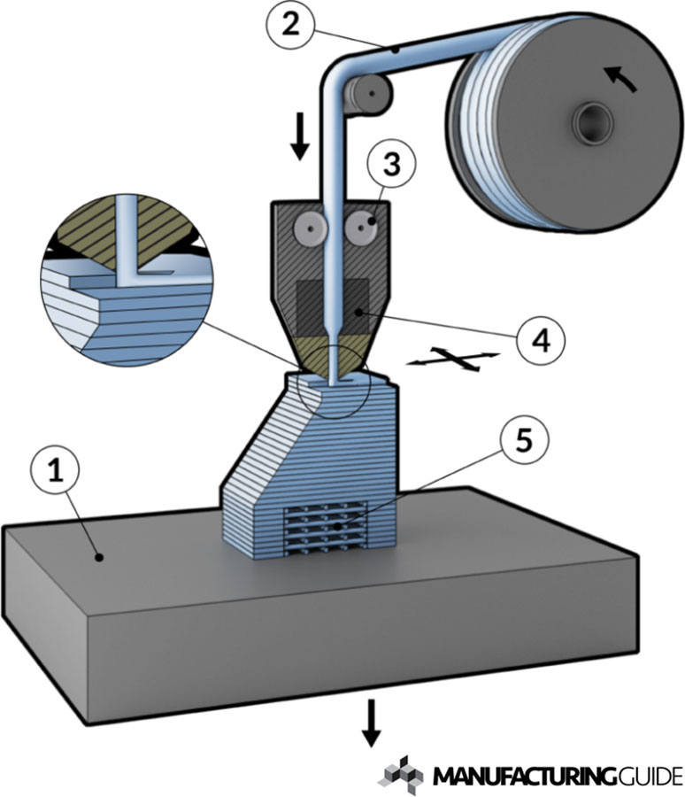 Printers with a single extruder can perform multi-color and multi-material operations but it is faster and easier to perform these operations with multiple extruders.
3D printing and multi-material functionality has spark a huge interest in material science; people have invented wood, ABS like PLA, nylon, flexible PLA, stone, carbon fiber, and other special filaments. Not only has 3D printing material undergone significant material research, but MIT found a way to enforce spider webs with carbon fiber to make it a stronger. It is also going to be interesting to see special blends of materials in creating objects. Multi-material functionality allows for optimized design: strain issues can be addressed with more flexible material and stress issues can be addressed with more rigid material. Currently this can be done if each part is done in different and distinct areas, but in the next five to ten years design software will allow for objects to be designed for a blend of materials.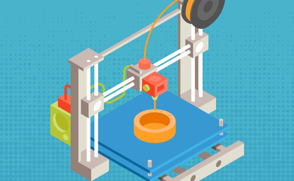 While the FFM printer have a wide range of available filaments, there is not a huge range of different resins available for SLA printing so it will be interesting to see what resins may be developed in the years to come.
Cooling extruder
One way to decrease the overall print time would be to increase the rate at which the filament is coming out of the extruder; however, the layer before must be fully solidified before the next layer of plastics is placed. One possible solution to this problem would be to add a special cooling head that would trail the hot print head to the hot plastic solidify faster.
Movement
Different 3D printers have different ways to move the extruder. A lot move the extruder in the Cartesian coordinate system or in the X, Y, and Z direction and the most common ways of doing it is by moving the extruder in the X and Y direction while the bed moves in the Z direction or have the extruder move in all three directions around a stationary bed.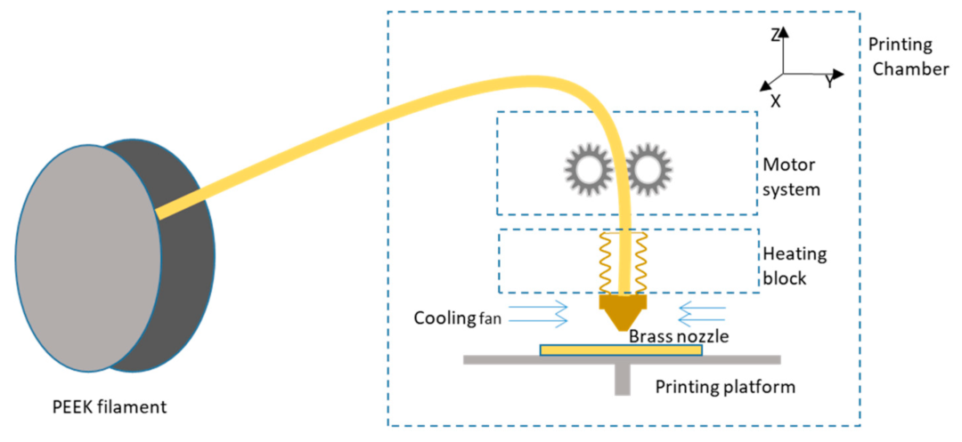 Having both the bed and extruder move in the X, Y, and Z direction could be a way to minimize the travel time.
Special nozzles
The extruder might be able to change the print head diameter at different times during the print similar to how cake frosting have special decorative tips.
Video Camera
Equipping 3D printers with a video camera–or a pair for stereoscopic view–will enable real time monitoring of the printing process either by algorithmic control or remote monitoring by human operators. The print job could be aborted and restarted, preventing wasted time and material. Depending upon what other postprocessing capabilities are available, or in a printer that supports both additive and subtractive manufacturing, a complex part could be reworked and completed.
Bed
Hot Bed
Many printers already have the functionality of heating the bed to improve print quality and protect against the warping during the print job.
Movement
As mentioned above, both the bed and extruder could move in the X, Y, and Z direction to minimize the travel time. As for the delta 3-D printers, they could have their circular base to rotate to make the travel time faster of the print head.
Auto-leveling
As someone who has used a variety of 3D printers, the leveling of the bed is one of the most annoying thing in 3D printing and even the slight height difference could stop print jobs from being completed. The Creatbot is the only 3D printer that I know of that has an auto-leveling bed and other great features.
Post Processing
Current methods for post processing include deburring, sanding, priming, airbrushing, and application of acetone. One of the biggest misconceptions with 3D printing is that the 3D printer can print out objects just as nice as store bought items.
There might an effective trade off between a very high resolution print with no post processing and a lower quality print and some post processing to make it smoother. The two major factors to be considered in these processes is speed vs structure integrity. If the goal is to achieve a faster time while not worrying so much about the strength of the object then the low resolution with the post processing seems to be better choice; however, if it is a functional part then the first option is a safer choice.
Missing Dimension: Information & Modeling
The CAD model development and related data flows are an important dimension of 3D printer functionality. Scanners, CAD design system, design rule checks, model repair tools, and other software that creates, modifies, or verifies the models needed for an object to be printed are undergoing as significant a rate of evolution as the functional blocks identified here. A truly complete functional block diagram would include them.
About the Author
Max Murphy is Mechanical Engineering student in his Junior year at California Baptist University. He is interested in the implications of 3D printing or positive manufacturing for mechanical design. He is currently an intern at Soundfit, one of the companies that is part of the Bay Area Advanced Manufacturing Hub (BAAM), where he is gaining hands on experience with a 3D printer and scanner and an intern at Neodyne Biosciences working with the R&D and Q&A departments.
About The Functional Block Diagram For 3D Printer
The 3D Printer Functional Blog Diagram is an original composition by Max Murphy. It is available for use under a Creative Commons Attribution-NonCommercial-NoDerivatives 4.0 License
Related Blog Posts
- 3D Printing IP Issues
- The Next Best Thing But Not Yet
- Chris Yonge on 3D Printing: Past, Present, Future
- Bay Area Maker Faire 2015
3D printing for the newest ones. From A to Z. Kinematics.
In this article, we will understand what 3D printing is and what the kinematics of 3D printers are.
1. 3D printing. What does she taste like?
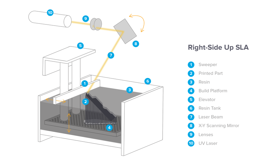
There are a lot of printing technologies, from FDM (FFF), which is used by more than 90% of printers on this portal, to SLA / DLP / LCD (with photopolymers) and SLS / SLM (powder sintering using powerful lasers)
At the initial stage, we are interested in FDM - layer-by-layer deposition of a molten rod.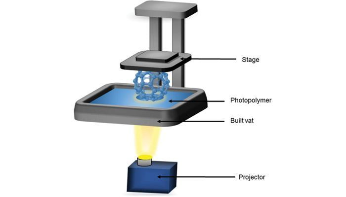 The picture below shows the hot end (Hot end) - that part of the 3D printer extruder where the rod is melted.
The plastic rod is fed through the Teflon tube and radiator into the thermal barrier, and through it into the heating block. It melts there and exits through the nozzle. The nozzle has a certain diameter, which is marked on it.
It is often made of brass, as the material is inexpensive and easy to process. The accuracy of printing depends on the nozzle. The smaller the nozzle, the more threads fit into one mm.
Heater and thermistor provide feedback for temperature control and regulation. That is, the voltage supply to the heater depends on what temperature the thermistor shows, and the processor compares it with the set one.
Next we see the heating block. A nozzle is screwed into it on one side, and a thermal barrier on the other.
The thermal barrier is used to minimize the heating of the plastic above the thermoblock.
[IMG]http://3d-makers.nethouse.ru/static/img/0000/0002/6151/26151635.2ofdbr37y8.W665.jpg[/IMG]
Most often made of stainless steel. It has a lower thermal conductivity than conventional, unalloyed steel. To prevent the rod from melting above the thermal block, a radiator is screwed on top of the thermal barrier and blown by a cooler. Everything is quite simple.
It is very common for melted plastic to leak through threads.
This means that the nozzle has not pressed the thermal barrier in the heater block. Therefore, when disassembling and assembling the hot end, we first screw the thermal barrier into the heating block, and then press it with a nozzle. If, when you twist the nozzle, there is a gap between the end of the nozzle and the heating block, then this is normal, the gap in order to press the thermal barrier with the nozzle.
In order to feed the bar at the right time and in the right place, a feeder is needed, that is, a bar feeder.
Sometimes it is performed combined with a hot end, and then this type of extruder (this is all together a hot end + feeder) is called a direct (direct), that is, a direct feed, without tubes.
The same feeder is made separately, and the bar is fed through a fluoroplastic tube. Such a system is called bowden.
This is to lighten the moving part. As for the positive aspects and disadvantages - each design undoubtedly has them.
Direct extruder:
1. Advantages:
a) More reliable due to fewer plastic feed connections;
b) Less picky about the materials it prints on, in particular rubber-based rubber is problematic to print on bowden extruders;
2. Disadvantages:
a) Large weight, due to this, during acceleration / deceleration, small ripples can be observed on the surface of the part;
b) Dimensions.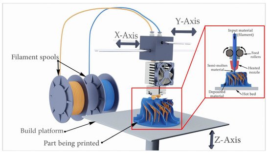 They greatly affect the plot area. Let's say, like in the picture above, a direct with 4 colors would be very huge. And for Bowden, this is just right.
Bowden extruder:
1. Advantages:
b) The coil does not twitch after the model, otherwise, when the coil turns with the direct are entangled, we will get a skip of steps, since the carriage will pull the coil along with it.
2. Disadvantages:
a) Retract settings (pulling the rod back during idle movements so that the molten plastic does not ooze out of the nozzle while expanding) is more difficult, since the rod is smaller than the inner diameter of the tube, it tends to stretch;
b) It is more difficult than on direct to select all gaps in order to print with various flexible plastics. Everyone who says that printing on Bowden is impossible with flexible plastics is blatantly lying. I am typing. And quite successfully.
Now we go directly to the mechanics and its calibration.
Part 2. Mechanics. What, how and what pulls?
There is a very limited number of kinematic schemes for which the firmware is written, and which work out movements quite tolerably.
Consider everything, from the most common:
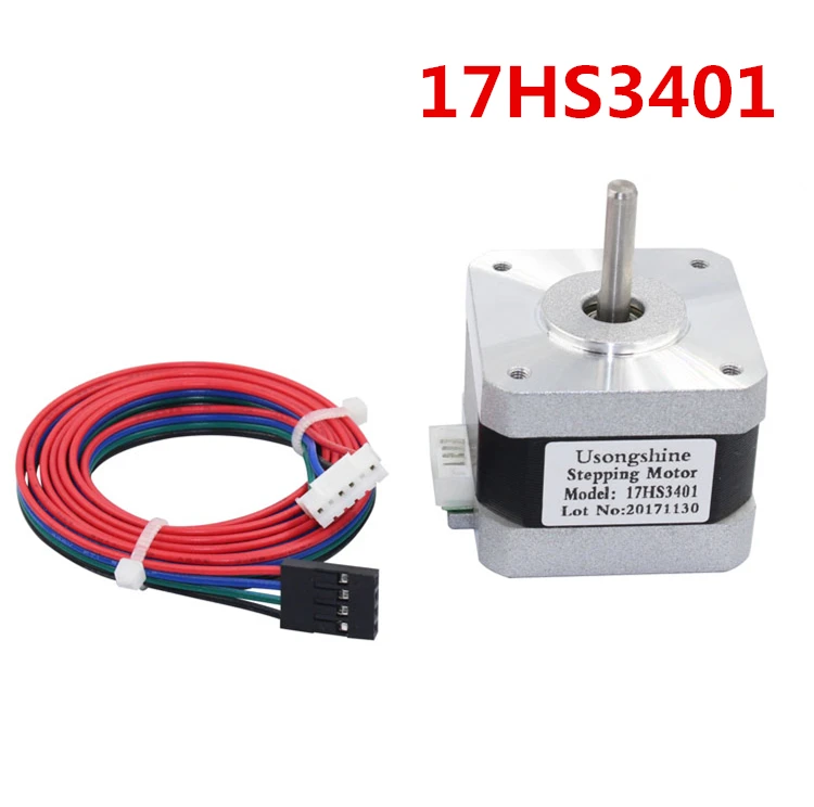
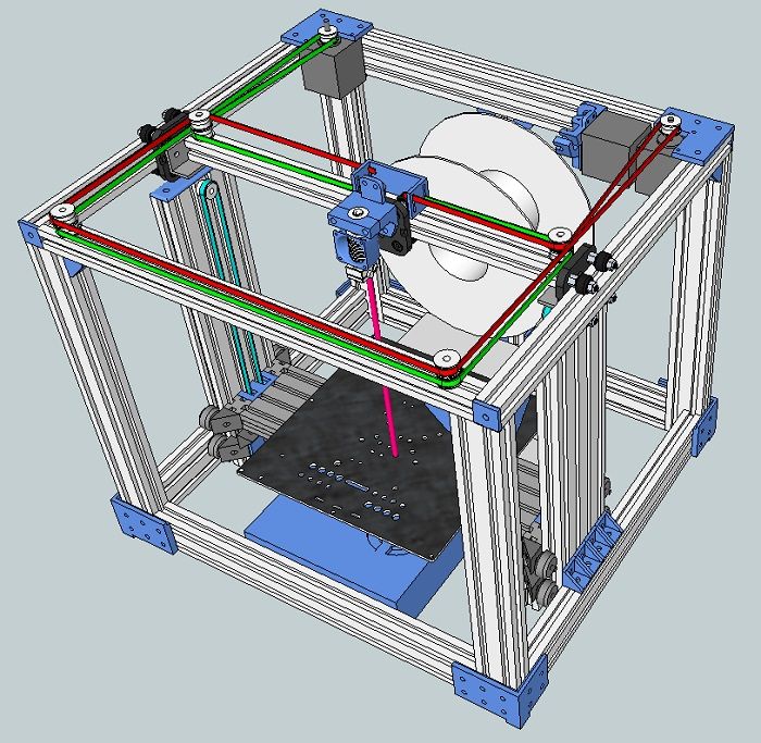
1. Design and kinematics from Joseph Pryusha (no need to read Prus, Prasha and so on, this is the name of a person, after all).
Movement along each of the axes is provided by its own independent motor. Movement along the Z axis (up and down) is provided with the help of 2 motors and with the help of a kinematic screw-nut pair. M5 studs are often used; recently, screws with trapezoidal threads have been increasingly installed.
Here is a trapezoidal screw. How studs with metric threads look I will not apply.
The only thing I will explain about moving along the studs and trapeziums is that for the production of trapeziums they take a calibrated rod and roll it between rollers at an angle.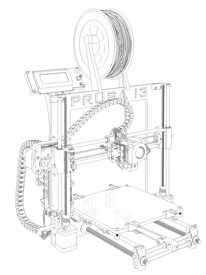 Get helical grooves. This method, a priori, gives better quality and step accuracy than building studs of far from the highest quality.
To connect 2 motors to one axle (and 1 connector) at the same time, the following scheme is used.
Connection in series, 2 wires soldered and the rest crimped. You can ignore the colors, the main thing is that the windings ring. A and B are windings, and 1 and 2 are terminals.
Advantages of this kinematics:
1) Independent movement of each axis. It is easy to catch to understand which axis skips steps. Kinematics migrated to printers from CNC milling, so many manufacturers make desktop milling machines on it, instead of an extruder they offer to install a laser for engraving or cutting, a spindle for milling boards, an extruder for chocolate or even dough to bake pancakes.
Pictured above is a ZMorph printer. It can be used as a printer (with one or two extruders), as an engraver (Dremel machine), as an engraving laser, and so on. A small presentation video.
Milling machine with this kinematics. I note that for milling it is necessary to use a screw-nut pair to move, and not belts, they are not designed for such loads.
Chocolate and pancake printers according to your design. It is worth noting that it is not recommended to use chocolates like Alenka or Babaevsky, since they already contain cocoa butter and during processing (melting and hardening) the result is unpredictable. It is necessary to use chocolate in galettes, such as the Belgian Callebaut, as it does not contain cocoa butter, and must be added for the final filling.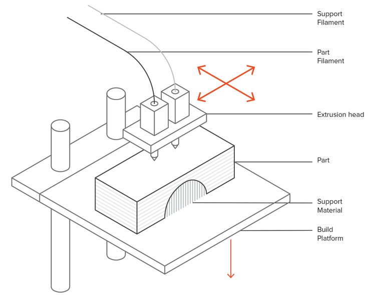 For this type of chocolate, each pack has a graph of its crystallization. It is desirable to take the oil in powder form. For more information, I recommend Google about tempering chocolate.
2) The kinematics are as easy as two fingers. Its very easy to assemble. Many even collect on old DVD drives.
3) Easily changed to suit your needs, the size of the extruder is also of little importance, as it protrudes forward and does not interfere with the movement of other parts. Many people put a second extruder, or make the nozzles swing so that the nozzles of one extruder do not remain on the part when printing with the second nozzle.
Therefore, for this kinematics, there are a huge number of extruder variations, for every taste, on a very famous site.
Disadvantages of this kinematics:
1) Complicated calibration. Yes, since the table 'jumps', it is difficult to print with high quality, because the part + table, with a sharp change in the direction of movement by inertia, tend to go further. Ugly print artifacts are obtained. And for high-quality printing, you need a small speed. In general, it all depends on the frame. My first printer was a Chinese pryusha. With acrylic frame.
Acrylic is not very hard. And as you know, the rigidity of the printer, like the CNC, is the most important thing. And it was possible to print more or less qualitatively at speeds of 40-50 mm / s. Then I transplanted it to a steel frame from MZTO.
And after that, without loss of print quality, I was able to print at speeds up to 100 mm / s.
2) Delamination. Due to the open case and the constantly moving platform, hot air, one might say, is constantly blown away, and by cooling the part excessively with drafts, we increase the already large shrinkage of nylons, abs and other capricious plastics. Someone sews a fur coat for a fabric printer, and someone is content with boxes.
But the goal, as always, is the same - to reduce the effect of drafts on the shrinkage of the part.
Key points for correct calibration of printers with this kinematics:
1) Place the printer on a level surface. Preferably horizontal. This requires a bubble level. Next, set the level of the position of the X axis.
2) Transfer to the home position. It is done either in the printer menu with the Home / Home command, if you are printing from a computer, then either with the G28 command in the command line, or with special buttons with the house icon.
Next, tighten the table screw so that the nozzle touches the glass. It did not press on the glass, but touched. We look at the light and twist. After that, move the extruder to another corner with the arrows in + X, + Y from the PC, or through menu
Turn the screw in the same way until it touches the nozzle. And repeat the operation for the remaining points.
I will try to save you from mistakes. In the photo of the printer above, the glass on the table is fastened with as many as 8 clamps. And it is quite possible that there will be a hump in the center. To avoid such problems, the glass should be fixed with 3 clamps. The plane is built, as is known from descriptive geometry, by 3 points. And calibration will be easier in this case. Just tighten the screw over the limit switch in Z.
For the nozzle to touch the glass in the middle of the side with 1 clip. Then we distill the hot end into the corner where there is another clamp, tighten the table screw, and repeat the operation with another angle.
Regarding wobble.
All sorts of anti-wobble systems such as installing a bearing in the upper support do not work.
Just because putting 4 far from perfectly even cylinders in perfect parallel and in the same plane is an unrealistic task. Especially on a flimsy acrylic frame with printed details.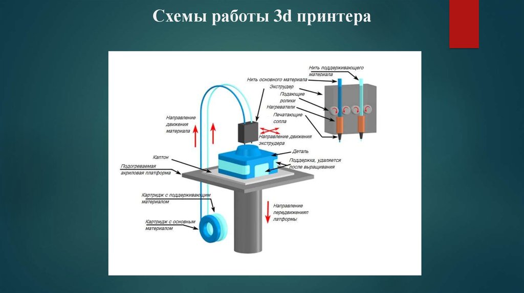 Therefore, if we take the straightness of the shafts as a constant, and set them parallel on the frame (purely hypothetically), and release the screws (from below the coupling for attaching to the motor) and nuts for attaching the X axis. Due to their curvature, the screws will spin like a mixer, but on printing will not be affected.
Otherwise, the design will work on who will be stronger in terms of bending resistance. And it will turn out far from a flat wall. Do you need it?
2. Kinematic design of Felix printers.
There are many such printers, such ones are made by MZTO (mz3d.ru), already mentioned by Felix. In fact, the kinematics are the same as those of the Prusa. axes independent of each other. Only now the table does not travel along one axis, but along two at once. Along the Z axis, and along the Y axis.
The design of the table is something like this.
A platform rides on the Z shafts.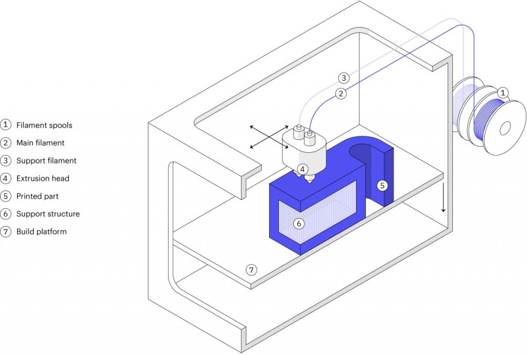 The engine hangs at the back. The table moves along the rails with the help of a belt. The hotend moves only along one axis. The design is very funny, since the table weighs much more than the hotend, and they try to move it along 2 axes at once.
Advantages of this kinematics:
1) There is no second motor along the Z axis. There is no notorious wobble simply because there are 2 shafts and 1 propeller. The screw should also not be fixed from above. If it's not a ball screw.
Ball screw is a separate issue. If we take a high-quality ball screw, say, from the same Hiwin, then it is manufactured according to at least the 7th accuracy class (if rolled, and if polished, then the class is even higher) and must be installed in bearing supports. On the drive side there are 2 back-to-back angular contact bearings, and on the other end a radial bearing with a loose fit to compensate for thermal expansion.
The purpose of mounting a ball screw is to ensure movement accuracy.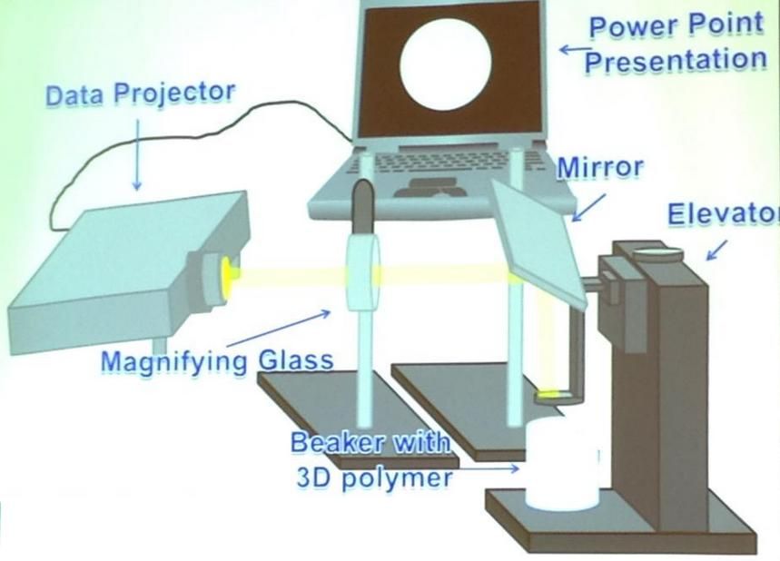 If it is installed incorrectly, money is wasted, and the accuracy will not be higher than a screw-nut pair with a trapezoidal thread. For FDM, trapezoidal accuracy is more than enough.
2) Plenty of space for a direct extruder. As in the previous kinematics, there is room for creativity, to select the one and only extruder that you like.
3) Rigid frame. It is possible to make a normal frame. Rigid, durable. Yes, even cast iron. The guys from Felix decided not to bother their heads and sculpt from an aluminum profile. MZTO went further, bent the steel sheet. And the shelf for the installation of the table was milled from a sheet of aluminum.
4) If we take the design of Felix on the profile, then by replacing a pair of pieces of the profile and the Z screw, you can increase the print area.
Just be sure to add stiffness. And it will turn out like a miracle of design thought. Big, meaningless and merciless.
Kinematic disadvantages:
1) Undoubtedly large twitching masses.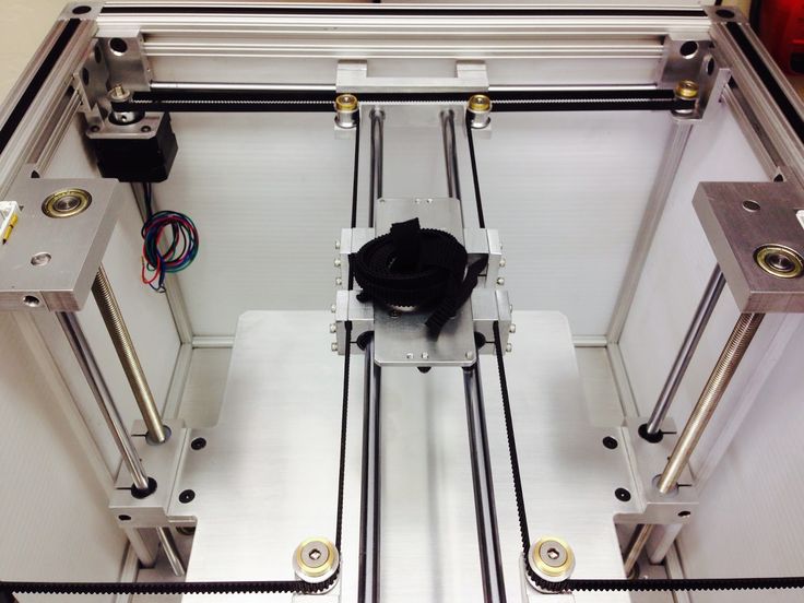 The table back and forth, and if you turn on the movement along Z during idle movements (Z-hope), then there will be a disco.
2) There is no way to make him a normal heat chamber. The table moves back and forth and the temperature gradient simply blows away. Hence the problems when printing with nylons or ABS. Small drafts in the room will easily show you where the crayfish hibernate, how the material shrinks.
The calibration of the table of this printer is similar to the calibration of the Prusa table, only slightly simpler. It is easier due to the fact that you do not need to level the X-axis, it is automatically set when assembling the frame. We bring the nozzle to the table and twist the lambs.
3. Ultimaker kinematics.
One of the most common variations of Cartesian kinematics.
There are not very many such printers, but they do exist. Variation from Zortrax deserves attention. A variant of the same Raise is closer to the classics.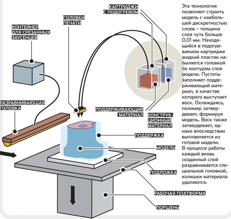
Zortrax has twin shafts, the reason is simple - they have a direct extruder with a full size Nema 17 motor. Raise Dual has a double direct extruder, so the classic 6 mm shafts are replaced by 8 mm. And the total weight of the 'head' is almost 900 grams.
Kinematics built entirely on shafts. They act both as guides and as pulleys. Kinematics also refers to Cartesian kinematics with independent movement along each axis by its own motor. Very picky about the straightness of the shafts. If you use curved shafts, you can get very funny artifacts on the walls of models. And they will be on all 3 coordinates. Most often it looks like a different thickness of the first layer and small waves along the walls. Therefore, all the salt and the high price of the original Ultimaker is only in high-quality components. Namely, in straight shafts. The belts are often used as ring belts, which simplifies their tensioning system, since it is important that all 4 belts are equally tensioned.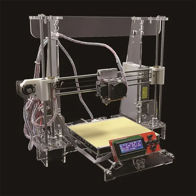
Advantages of this kinematics:
1) The table only moves along one axis. vertical. And the temperature gradient in no way suffers from this. The table is cantilever, so it is desirable to provide stiffeners or take this into account with the thickness of the table.
The metal fold on the table acts as a stiffener.
Many Chinese clones are equipped with such stiffening ribs for the table.
2) Despite the seeming complexity of the kinematic scheme, it is simple and each axis moves with its own motor.
3) The body is closed, which protects against drafts, and therefore delamination. Some put an acrylic door to heighten the effect.
Disadvantages of kinematics:
1) For good printing, it is not enough to buy a pack of even rollers. Collecting all these shafts correctly together is another task. At the same time and buy good bearings. Not that, Chinese junk, which is often sold on Ali, but normal bearings. If the bearings that are placed in the housing rotate poorly, the print will be jerky and with a shift in the layers. The consequences can be asked from Vanya (Plastmaska). Also, when buying leopard bushings, brass bearings with graphite inserts, be prepared for the fact that they will play. And if there is a backlash, the whole structure will knock.
And also, the Chinese like to push brass instead of bronze. And with even wear of brass and graphite, there will be an oily sticky black film on the shafts, which will make the movements harder. Ilya (tiger) offers good bushings. He also wrote about these difficulties.
2) All shaft parallels must be set correctly. I suggest using this device.
4 shafts that go along the walls of the body automatically stand up correctly, but it is important to set the crosspiece correctly in order to get angles 90 degrees in the XY plane.
3) The design does not provide for an increase in the printable area with a couple of profile pieces, so the size of the hotend matters. Direct is difficult to put, but you can if you want.
Calibrating the table couldn't be easier. The table is often on 3 attachment points. Move the hot end by 3 points and turn the thumbs.
4. Kinematics used by Makerbot.
Also very widespread. In particular, printers from Makerbot, BQ, BCN3D, Magnum, magnum clone Zenit and quite tolerable makerbot replicas Flashforge and Hori work on this kinematic scheme.
In this case we have independent movement of each of the axes, with a Z table and all the resulting sides.
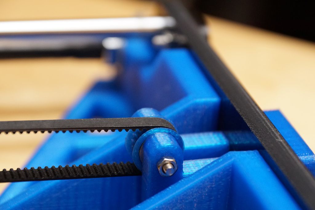
The main drawback is that the engine hangs on one side of the rolling beam, creating a kind of imbalance. This shortcoming was compensated in a two-extruder version - BCN3D Sigma. There, each bowden head has its own engine to move along the beam. And they are installed at the edges of the beam and balance each other.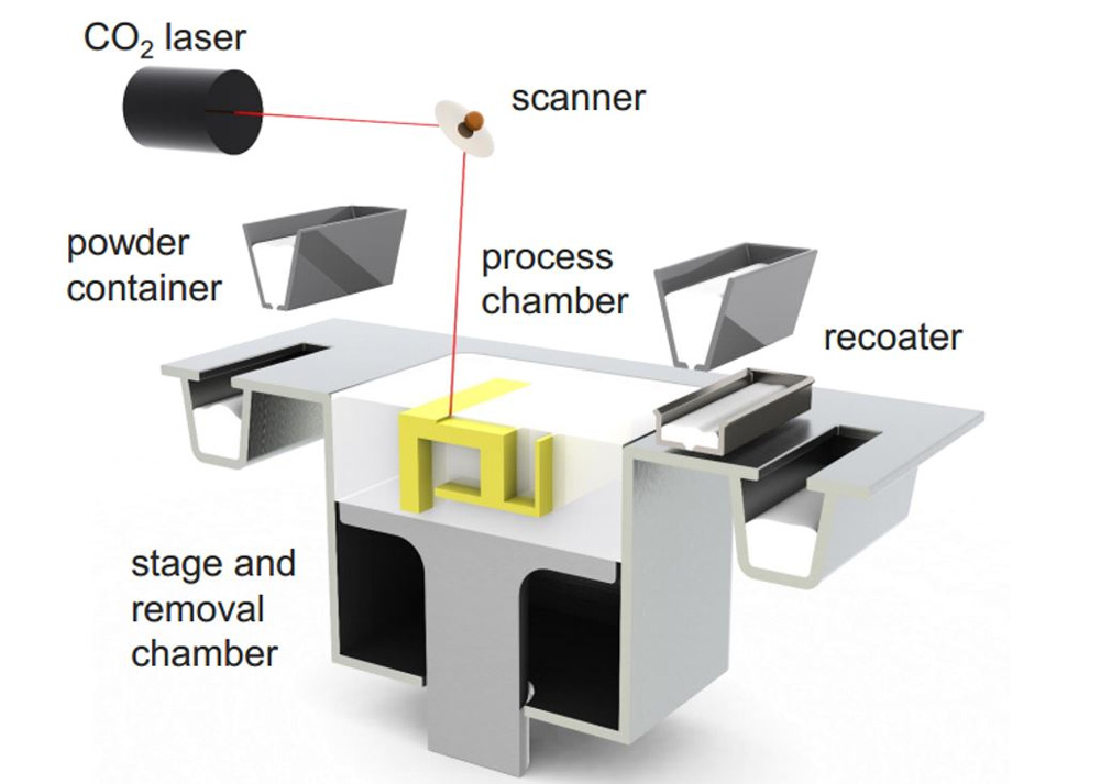 For uniform movement of each of the edges of the beam, 2 shafts, pulleys and belts are used. Belts must be tensioned equally.
Advantages of kinematics:
1) Independent movement of each axis.
2) Z-moving table. The temperature gradient does not suffer from 'blowing'.
3) Enclosed housing. If not closed, then there is a quite normal chance from the point of view of aesthetics to close it.
4) Scalable kinematics possible. Various BigREPs and others with 1m print areas use exactly this kinematics, as various H-bot/CoreXYs will ring like hell due to the presence of 4-5m belts and their stretching during accelerations.
Disadvantages of kinematics:
1) Unbalanced masses on the moving beam, hence the maximum print speed, with acceptable quality no more than 60-80 mm/s. Some manage to balance them and it is not so noticeable.
2) Bulky structures on the shafts to avoid unbalance during movements.
3) Make sure that the belt tensions on the right and left are the same.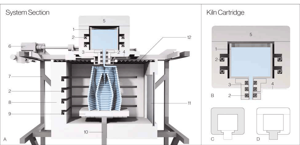
4. H-bot/CoreXY kinematics.
Next in distribution. Also Cartesian. Two motors are stationary, but move the carriage along the rails with one long piece of belt, or with two, but shorter. The math is more complicated than the previous ones, as it is necessary to synchronize the rotation of both motor rotors. That is, to move along each axis, you need to rotate both motors, and to move diagonally, only 1.
[IMG]http://www.doublejumpelectric.com/projects/core_xy/pics/hbot.svg[/IMG]
In fact, the mathematics for rotating motors is the same, but the implementation in mechanics is different. One of the biggest disadvantages of the H-bot over the CoreXY is that the belt tends to rotate the beam as it moves.
In the picture on the left, this is noticeable, the forces on the right and the forces on the left create a torque. Therefore, to implement this kinematics, the rigidity of the kinematic scheme is necessary. Most often it is implemented in rails.
With rigid beam. Some do, of course, on the shafts, but in the end - this is not a fountain.
And then they realize this and move to the rails.
For they are both easier to assemble and set up, and it is not necessary to invent carriages so that the shafts do not need to be fixed well.
CoreXY, unlike the H-bot, is driven by two belts.
And so, for ease of understanding, I will describe the positive and negative aspects of each variation of this kinematics.
H-bot.
Advantages:
1) Only one belt is needed, and the scheme provides for its operation without twisting.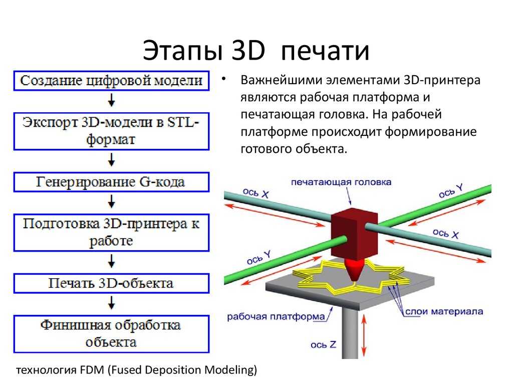
2) It is more convenient to tension one belt than 2, so only one normal tensioner is needed in this scheme.
Even so.
Disadvantages:
1) The belt tends to stretch over time, and since the amount of stretching directly depends on the length, it is necessary to monitor its tension. Otherwise, you will get ugly waves on the surface before the stops.
With a loose belt tension, the carriage will have this play.
2) It is necessary to set the rollers strictly perpendicular to the XY plane, since if the roller is slightly skewed, the belt will be eaten against the roller shoulders. And we will get such a bullshit.
Tested in the skin and ZAV printer. Therefore, I always recommend that the rollers be fixed normally, and not cantilevered, in order to avoid bending the roller axis from belt tension.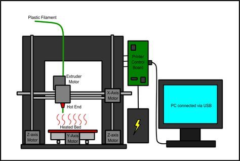
3) Complicated mathematics, due to which at speeds above 100 mm/s there may be problems with the lack of resources of 8 bit boards.
CoreXY.
Advantages:
1) Two short pieces of belt. They are easier to find than one long one.
2) The forces balance the beam, but do not tend to turn it, so these kinematics can also be assembled on shafts.
Disadvantages:
1) There are schemes with belt twisting and belt transition from one level to another - this is not very pleasant for a belt. Especially when one belt rubs against another. This moment is on video.
:{}
2) The difficulty of tightening the belts. They must be tensioned equally, otherwise the tension forces will tend to turn the carriage.
3) Complexity of assembly and development. It is necessary to maintain the verticality of the rollers, relative to the horizontality of the platform for installing motors and rails. A slight misalignment of the rollers will cause the belt to tend to slide down the roller, and if it rests against the shoulder of the roller, it will creak, if the shoulder is large, and if it is small, it will try to drive into it, as in the photo from the h-bot description .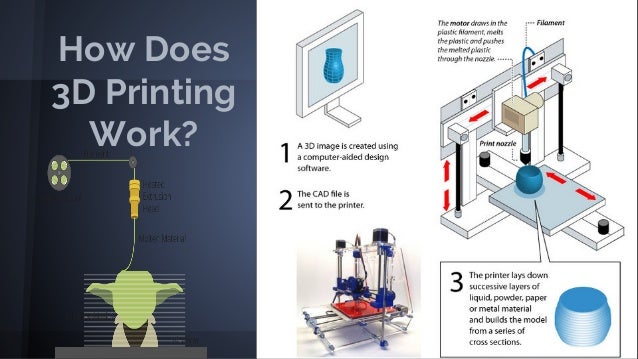
The general disadvantage of kinematics is poor scalability. That is, it is very problematic to set such a kinematics for a print area larger than 300 * 300 simply because of the elongation of the belt during printing. For small printers with high print speeds - one of the best kinematics.
5. Delta kinematics.
The kinematics are based on the movements of the delta robot.
Only the hot end is installed instead of grips. It has its own set-up problems, but it can take a very long time to print. It is rare when direct extruders are installed, since the effector (a platform for installing a hot end) is often mounted on magnets and it is necessary to unload it as much as possible. But in order to reduce the length of the tube (more specifically, the effect of the length of the tube on the print quality due to the correct adjustment of the retracts (pulling the plastic rod back to reduce its leakage from the expansion)) on the print quality, the extruder is hung on the same carriages, but on separate hangers. This reduces the length of the bowden tube and increases print quality.
Advantages:
1) Easy to customize. To increase the height, it is enough to buy 3 pieces of a longer profile, and increase the maximum height in the settings.
2) Takes up little space. It is more often high than bulky in length and width, due to this compactness.
3) If you make a light effector (carriage on which the hot end is installed), then you can achieve high speeds without losing print quality.
4) Vertical movement is the same as XY movement. Thus, there is no sticking of linear bearings on the table crossings, as in Cartesian printers, no extra motors rolling on the beam...
5) The absence of protrusions makes it possible to close the housing and stiffen the frame.
6) The aesthetic part - it's more interesting to stick to the work of the delta.
Disadvantages:
1) Difficult mathematics of movements, it is recommended to install 32-bit boards at once.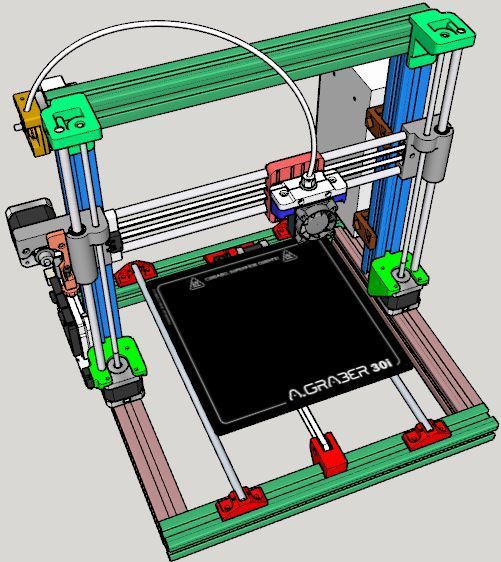
2) Complicated setting. A common problem in tuning is to remove the so-called 'lens', because each rod rotates with a radius, and if the tuning is incorrect, your printed plane will be either a convex or concave lens.
3) It is difficult and expensive to make a rigid frame, so that it would not dangle from the constant jerking of the carriages.
4) Difficulty installing a direct extruder. It turns out to be heavy, and since many deltas are made on magnets, it will not be possible to accelerate. Although, there is one neat and easy solution - installing a ready-made direct extruder with a gearbox. Like E3D Titan Aero or Bondtech BMG.
5) Parts precision problems - any unevenness and misalignment will be visible even if they are on the same axis. And they add up along the axes.
To sum up , do you want a small printer (not larger than 300*300 mm) with nimble kinematics? Then you should go to Ultimaker or H-bot/CoreXY. Need a printer with a large printable area or 2 independent extruders? Then to Makerbot. If you print vases, hookahs and sufficiently high details - delta. For everything else, there is a classic - Prusa. Experiments with double carriages, chocolate, engravings? Yes, anything. And most importantly - cheap.
You can even screw on 4 colors.
Kinematics of 3D printers: what are the best types
Kinematics of 3D printers - which device to choose?
The print quality of a 3D printer and how it works depends on several factors. One of the important indicators is kinematics. This article discusses its main types and their features.
- What is the kinematics of 3D printers?
- Types and types of kinematics
What is the kinematics of 3D printers?
Each 3D printer has its own kinematics.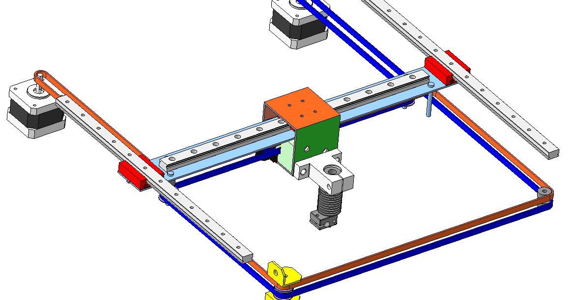 Models are equipped with a platform and an extruder. These parts move in a certain direction relative to each other. Kinematics in such a device means the scheme along which the extruder and platform move.
Types and types
There are five types of 3D printer kinematics. The principle of operation of the device and the method of processing the workpiece depend on their features.
Cartesian 3D printers
The most common are 3D printers with Cartesian kinematics. They are based on the Cartesian coordinate system, they work in the X, Y and Z axes. They set the coordinates by which the print head changes position relative to the platform. The printhead has limitations in terms of movement in three axes.
- The extruder moves up when the platform moves in the horizontal X or Y axis.
- The platform moves up in the Z axis, the extruder can move in the horizontal directions at this moment.
- The platform moves along one of the axes in height, the extruder rises along the other axis.

- The platform is static and does not move, the extruder moves in all three axes.
- The extruder moves along the coordinates in height, and the platform moves along the X and Y axes.
The most common options during operation are the first and second.
Cartesian kinematics has a number of advantages.
- This is a simple motion pattern suitable for hobby printing. Many budget models work on its basis.
- The printer can be produced in any dimensions, if necessary, it is upgraded.
- Consumables are freely available. Users are offered a large number of materials and colors.
- The printers can be shipped unassembled. This feature allows beginners in the world of 3D printing to understand the principle of the mechanism.
- Devices based on the Cartesian system are suitable for mass production of parts. They are designed to create blanks of different sizes.
Among the shortcomings of printers built on the principle of three coordinate systems, two factors stand out:
- models are bulky, after assembly they take up a lot of space on the desktop;
- The print speed is slow.

Cartesian kinematic printers suitable for hobby printing. They help beginners understand the process of work and learn how to create models.
Example of printing on a device with Cartesian kinematics.
Varieties of Cartesian kinematics CoreXY and H-Bot
The CoreXY has two feed belts, while the H-Bot has only one, but it is long - this is the main difference between the two varieties. The common feature in these devices based on Cartesian kinematics is that the platform moves only along the Z axis. The horizontal X and Y axes are moved by a pair of motors mounted on the frame.
Two motors are responsible for the movement along the horizontal axes, one motor along the vertical ones. Such kinematics is common not only in amateur printers, but also in professional ones.
CoreXY and H-Bot based 3D printers are more expensive than conventional Cartesian models. For the production of their cases, a metal alloy or composite materials are used. Rail guides unleash the potential of high-quality printing. This kinematics allows you to achieve good detail with fast printing.
The advantages of CoreXY and H-Bot are:
- high print speed;
- quality detailing of models;
- professional grade use.
But not without drawbacks:
- H-Bot is not implemented on steel shafts;
- it is necessary to constantly monitor the tension of the belt so that there is no play;
- high cost of instruments;
- belts can wear out quickly if they rub against neighboring objects during operation, this factor must be taken into account during operation;
- the pulleys on which the belts move must be located strictly perpendicular to each other.
Cartesian kinematic printers are widely used in various industries. They are distinguished by high print detail, a durable metal case, and high-quality components.
Help! Cartesian kinematics allows you to create detailed objects at high speed.
Delta Printers
Delta kinematic printers differ from their competitors in a number of ways. The table remains stationary, and three fixed axes are used to move the print head at once. In such devices, there is no division into the X, Y and Z axis. To move the carriage sideways, you need to lower one axis, and raise the rest.
Help! In the production of 3D printers, the Delta kinematics has not yet found wide distribution. This is a promising direction, which is currently being developed by developers.
Already existing delta printers offer the following advantages.
- Small dimensions. Devices do not take up much space on the desktop, they are tall, but not wide.
- High print speed. Models can process 300–400 mm/s.
- A new approach to blank making. The equipment does not print using the same technology as Cartesian. It is interesting to watch the process of processing the model.

Deltas also have a few drawbacks.
- Calibration complexity. A lens is formed on the printed surface, due to which it is impossible to fully calibrate the printing process. This is the main factor slowing down the mass introduction of kinematics.
- Poor accuracy. High print speeds sacrifice accuracy. All axes perform small movements, errors occur.
- Computing power requirements. Deltas are equipped with 32-bit boards, which is why they do not support interaction with 8-bit systems.
- The frame must be rigid. This is necessary to avoid backlash, deviations and distortions.
- Not all extruders will fit. Deltas have weight restrictions, so direct type extruders are not allowed.
Printing accuracy remains high.
On deltas, you can build high-quality vertical models, even with large dimensions. There are no protruding parts on the body, which allows you to independently increase its rigidity.
Polar
The polar kinematic scheme is represented by only one company - Polar.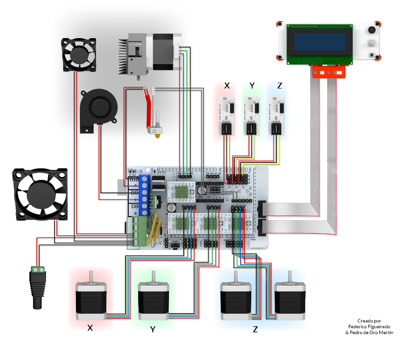 The essence of this technology lies in the fact that it does not have positioning along the X, Y and Z axes. The position of the extruder is set by the angle and radius. The platform of polar 3D printers is round in shape, it moves only along the horizontal axis and only rotates in a circle. The extruder moves up and down.
The advantages of 3D printers based on polar kinematics are:
- the ability to create large objects;
- high energy efficiency;
- material savings;
- small dimensions.
But there are also disadvantages:
- low printing accuracy, which was started by Polar representatives;
- platform does not warm up during operation;
- material restrictions - ABS plastic cannot be processed.
Polar printers are less accurate than Cartesian and Delta printers. The manufacturer recommends using such models for educational purposes; they are not yet suitable for professional printing.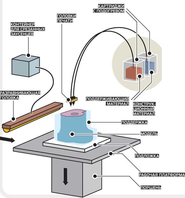
Printing example shows that accuracy cannot be achieved. All features are blurred, the figure lacks sharpness and clarity.
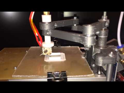
With robotic arms
Printers with robotic arms are a design with a mechanically programmable extruder gripper arm. This is a multifunctional robot: it can carry out welding, painting, milling, etc.
The extruder can move in different directions: in layers, along complex paths in three dimensions, at different angles. Thanks to this set of functions, it is possible to create complex structures.
The main advantages are:
- versatility: the device can perform several types of tasks when replacing the extruder;
- are suitable for industrial applications: you can print large objects with almost no size restrictions.
But there are also disadvantages:
- low accuracy: such equipment is inferior to Cartesian kinematics;
- large size: devices take up a lot of work surface space.
These models are not suitable for professional 3D printing. They can be considered as an object for a hobby or a tool for it. For industrial purposes, such devices work only when high precision in the execution of parts is unimportant.
SCARA
SCARA (Selective Compliance Articulated Robot Arm) is a kinematics based on horizontal rotation of the platform. The movement is achieved by the articulation of the linkage mechanism.
These instruments are highly accurate and repeatable, and operate with a minimum of noise and vibration. SCARA also surpassed the Cartesian models in terms of processing detail: the difference is that the former work noticeably faster.
Advantages of such kinematics:
- print accuracy;
- high workpiece processing speed;
- small dimensions and weight.
But there are also disadvantages:
- stiffness restrictions in the area of the X and Y axes;
- high cost;
- is not the widest area of use.
SCARA kinematic devices are devices that combine the functions of a 3D printer and a manipulator. Device actions are programmed through software or an installed mobile application.
The choice of kinematics for 3D printers depends on the requirements for technology and application.
- Cartesian kinematic models remain the most common. They combine high accuracy, good speed, small dimensions. They can be used for amateur 3D printing. They work in a Cartesian coordinate system, the platform and the extruder move along the X, Y, Z axes.
- CoreXY and H-Bot are varieties of Cartesian kinematics. They are highly detailed blanks, suitable for professional use. Their disadvantage is the complexity in the process of operation. The user must constantly ensure that the belts do not come into contact with foreign objects and are well tensioned.
- Delta printers are uncommon models whose weak point is print accuracy. In the process of working with the device, there are problems with calibration, as well as with the choice of extruder.

Learn more