Creating stl files for 3d printing
How to Prepare STL Files | Stratasys Direct
How to Prepare STL files
STL is the standard file type used by most additive manufacturing systems. STL is a triangulated representation of a 3D CAD model. Below you will find instructions on how to convert CAD to STL for many popular platforms.
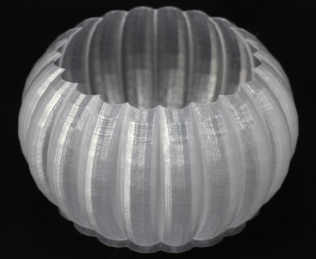
The triangulation (or poly count) of a surface will cause faceting of the 3D model. The parameters used for outputting a STL will affect how much faceting occurs (Figures 2 and 3). You cannot build the model smoother than the STL file. If the STL is coarse and faceted the physical 3D printed model will be coarse and faceted as well. However, the smoother/ less faceted your surface is, (the higher the poly count or triangulation) the larger your file. 3D printing can only accept a certain file size; therefore it’s important to find a balance between your model, its desired surface, and the 3D printing process of your choice.
An example of course triangulation.
An example of fine triangulation.
Your other option is to skip the process below as we offer instant quoting using just your native CAD file.
Simply sign-in, upload your CAD file(s), make your desired selections, click order, and get parts as fast as 2 days!
Yes, it is that easy.
Upload Native CAD here
When exporting to STL in your CAD package, you may see parameters for chord height, deviation, angle tolerance, poly count, or something similar. These are the parameters that affect the faceting of the STL. We’ve compiled tips on exporting for the best “surface: file” size ratio below.
Preparing your files
The following step-by-step instructions for converting CAD files to STL came from each CAD software company’s website or from 3D printing and design user forums; it’s an overall simplified step-by-step process from the greater 3D printing community. If your CAD software is not listed below or if you require additional assistance, please contact your CAD software technical support for information about exporting to an STL.
The CAD softwares covered below:
3D Modeling for Beginners
- Tinkercad
- SketchUp
3D Modeling for Engineers
- Autodesk Inventor
- CATIA
- IronCAD
- Rhinoceros
- PTC Creo Parametric
- Solid Edge
- SolidWorks
- NX
3D Modeling for Artists
- Blender
- ZBrush
- Maya
Don't have CAD software? SolidView is an affordable solution for non-CAD users to prepare STL files from many popular CAD formats. Start your free trial today.
Tinkercad
You can also just load your native CAD into our online quoting tool to get instant pricing!
Tinkercad is great for 3D printing simple geometrical objects. Its interface was created with 3D printing in mind.
- Design > Download for 3D Printing > .STL
SketchUp
You can also just load your native CAD into our online quoting tool to get instant pricing!
SketchUp does not offer STL creation directly within the program. Download the extension for .STL here (note: this plugin is open-source and updated frequently).
- Download and install the plugin
- Select Tools > Export to DXF or STL and select the units for your model (millimeters is recommended)
Tip: SketchUp isn’t inherently built for model production therefore it’s useful to check your SketchUp file for additional feature accuracies once it’s exported from the interface. We recommend uploading your SketchUp file into Meshmixer (a free program from Autodesk) to check your file for faceting and fix any surface flaws.
Note: We don’t recommend Sketchup for use with 3D printing as it does not export well and is best for early design sketches rather than producing physical models.
Autodesk Inventor
You can also just load your native CAD into our online quoting tool to get instant pricing!
-
-
- Select IPro > Print > 3D Print Preview
- Select Options and choose desired resolution and click OK
- Within the preview window, select Save Copy As or Send to 3D Print Service
- Save As type to STL File (*.
 stl)
stl)
-
Note: The “High” setting will also produce the largest file size. From Low, Medium to High, the hairdryer sample file in Inventor went from about 6.7MB to 17.6MB to 50MB.
Tip: Before finalizing your export, select the Options tab. Within this window, you can select the resolution (faceting) for your model (High, Medium, Low and Custom) and check that your units are correct. The “High” setting will produce a large file size. Autodesk Inventor allows you to save both individual parts and assemblies in STL format, at all design levels. For a quick overview of designing in Inventor, click here.
To check your modifiers have been applied before exporting:
- Tools > Rebuild All (this ensures that the design data contains recent changes, and that it is not corrupt)
- File > Save Copy As > STL (.stl)
- Select High and click OK
Note: To change the values associated with each of the resolution settings (High/Medium/Low) you need to edit the Windows registry.
CATIA
You can also just load your native CAD into our online quoting tool to get instant pricing!
- Select STL command (we recommend setting maximum segmentation to 0.015 mm)
- Select the model > Yes > Export
Note: CATIA V5 is capable of creating STL files from CATPart files, but not from assemblies (CATProduct files) or geometrical representations (car files). Therefore, source files, including those saved in a neutral format (i.e. STEP or IGES), must be saved as CATParts. If the source design was saved as an assembly, it is imported to CATIA as a CATProduct. To create an STL file from it, you must first convert it to a multi-bodied part. The procedure described below is one of several methods for doing this.
Saving CATProduct files as CATPart Files for 3D printing:
- File Menu > Open > select your source file (assemblies import as CATProduct)
- Save the imported CATProduct file
- Select File > New > Part > Name the new part
- Select one component from your master CATProduct File and copy it
- Paste the component in a new part window
- Repeat steps and until you have copied all of the components and pasted them as individual parts
- Once you have the assembly completely separate into individual components, select File > New Part
- Copy each of the individual components from the working files and paste them into the new combined model file (the geometries of all of the parts should retain and align correctly in the combined part)
- The new part is now ready to be exported as an STL file
- Select Tools > Generate CATPart from Product
- Finally, Select File > Salve As > Save as type: STL
Tip: Occasionally some of the components may not align correctly in the combined part because of the way the original assembly was designed. To align parts, select Insert Menu > Constraints Feature.
Before saving the file, it is advisable to review the settings that determine model accuracy and file size. To see these parameters:
- Tools > Options
- In the Options dialog box, display the Performance tab
- Under the General category (on the left), select Display
- Review 3D Accuracy settings
Tip: Curves’ accuracy ratio: The higher the setting, the smoother the surface will be when dealing with complex geometries, especially if surfaces contain sudden small changes with small radii (like the bumps on a golf ball).
IronCAD
You can also just load your native CAD into our online quoting tool to get instant pricing!
- Right-click on the part
- Click Part Properties > Rendering
- Set Facet Surface Smoothing to 150
- File > Export
- Select .STL
Note: IronCAD can export in many file formats depending on your geometry.
Tip: When working in assembly mode, you must save each of the component parts as individual STL files. The procedures for doing so are described below.
Saving a model design in STL format:
- Open the model design in IronCAD.
- Right-click on the part and select Part Properties > Part dialog box
- Make sure that the Rendering tab is displayed
- Change the Surface Smoothness setting to an appropriate value for your model.
- If you have not established an appropriate value, try 150. The higher the number, the smoother the model surface will be.
- Change the Max Edge Length setting to an appropriate value for your model.
- If you have not established an appropriate value, try 0.05. This setting produces good results, but increases file size and may require several minutes to render the model to STL format.
- To create smoother model surfaces when designing spherical and torus geometries, select the Triangulated Mesh check box.
 Selecting this check box results in larger STL files, but may produce smoother curves in models. If the surfaces of the model design are planes, this setting does not improve the results.
 - Click OK to save the settings and close the dialog box.
- File > Export > STL
- In the Stereolithography dialog box, make sure PC is selected, and select the Binary Output check box.
- Click OK to save the settings and create the STL file.
Rhinoceros
You can also just load your native CAD into our online quoting tool to get instant pricing!
- Select Object
- Mesh > From a NURBS Object
- Select Polygon Mesh > Detailed Controls
- Maximum aspect ratio: 2.0
- Perspective > Rendered View > Observe smoothness and confirm it meets standards
- To check that your mesh is uniform: Select the new object mesh > Analyze > Mass Properties > Volume
Rhinoceros 4
- File > Save As
- Select File Type as STL
- Select File Name > Save
- Select Binary
- Select Detail Controls from Mesh Options
- Max angle = 20, Max aspect ratio = 6, Min edge length = 0.
 0001
0001 - Click OK
Tip: Check your objects geometry and surface in the Object Properties tab to ensure object uniformity.
Rhinoceros Version 3 and Later
Rhinoceros enables extensive control of STL properties when saving designs as STL files. Because Rhinoceros software is surface-based, the complete model design (even if an assembly) is saved as a single STL part.
Saving a model design in STL format
- Select Part > File > Export Selected > In the Save As Type box, select Stereolithography (*.stl)
- Click Save
- In the STL Mesh Export Options dialog box, set the STL tolerance – the maximum distance allowed between the surface of the design and the polygon mesh of the STL file.
- If you do not know the other settings appropriate for your model design, try these:
- Tolerance: Less than half of the printer’s resolution. For example, the setting shown in the figures above (0.01 mm) is a good setting for printing models at a resolution of 0.
 03 mm
03 mm - Maximum Angle: Default
- Maximum Aspect Ratio: Default
- Maximum Edge Length: Clear
- Maximum Edge Length: Clear
- Maximum Initial Grid Quads: Default
- Refine Mesh: Check
- Pack Textures: Check
- Click OK
- In the STL Export Options dialog box, set the file type as Binary and click OK
- Note: If the Export open objects check box is selected, STL files will be created for each of the objects currently open. If this check box is cleared, an STL file is created for the selected object.
- In the STL Export Options dialog box, set the file type as Binary and click OK
- Tolerance: Less than half of the printer’s resolution. For example, the setting shown in the figures above (0.01 mm) is a good setting for printing models at a resolution of 0.
- If you do not know the other settings appropriate for your model design, try these:
Important: STL files are suitable for 3D printing if the models they describe are “watertight”, that is, they do not contain holes or gaps. If an error message appears, click Cancel and fix the model design before saving it as an STL file. Steps for fixing mesh in Rhinoceros are detailed below.
Troubleshooting Model Designs
If a model design contains holes or gaps, it is not suitable for 3D printing. Before saving it as an STL file, you must make it “watertight.”
To close holes and gaps in a model design:
- Check your object for errors: Command = Checknewobjects
- Surface errors will display
- Delete problem surfaces: Command = Selbad
- Command: Rebuildedges
Analyze Naked Edges:
- Analysis > Show Edges/ Edges Off > Command = Showedges
- Select object > Enter
- Within dialogue box, select Naked Edges
- Highlighted lines are naked edges and must be joined to the rest of your model
Fix Naked Edges
Option 1:
- Command = _Mesh
- This will create a mesh from the NURBS geometry (save your original NURBS file before doing this)
- Command = _Showedges
- This will detect naked edges
- Command = Fillhole
- If you cannot find the Fillhole command, open your Tools tab and select Toolbar Layout
- From the menu, check the box for Bonus Tools
- The Bonus Tools window will open
- Select Fill Mesh Hole
- If you have trouble, make sure you have the right updates installed
Option 2:
- Click the Mesh from Surface/ Polysurface icon from toolbar
- Polygon Mesh dialogue box will open
- Click Detailed Control > Polygon Mesh Detailed Options dialogue box will open
- Enter desired settings > OK
- Select entire object
- Tools menu > Polygon Mesh > Weld
- Command = 180 for angle tolerance
- The Weld command will merge adjacent triangle points when 180 angle tolerance is set
- Validate the object is watertight
- Command = SelNakedMeshEdgePt
- If the resulting object contains holes or gaps, the mesh needs fixed
- Repeat the Save As procedure
PTC Creo
You can also just load your native CAD into our online quoting tool to get instant pricing!
3D printing in PolyJet:
- File > Print > 3D Print
- Define Material
- Define STL resolution
- Tip: Check your file for printability through the Printability Validation Tab
Retired PTC Creo Formats: Pro/ENGINEER
- File > Export > Model
- Set type to STL
- Set chord height to 0.
 The field will be replaced by minimum acceptable value
 - Set Angle Control to 1
- Click OK
Exporting your STL file can be done at all levels of design, for both individual parts and assemblies. When dealing with assemblies, you can specify parts of an assembly to either include or exclude from the resulting STL file. Use the procedure below for saving both parts and assemblies as STL files for eventual 3D printing.
To save a Pro/E as an STL file:
- Check that the model design is continuous and “watertight”
- This step is especially important if the design was imported from a neutral design format because non-continuous bodies are likely to result in defective models
- To check for continuity:
- View the model with hidden lines displayed.
- From the View menu, select Display Setting > Scheme > PreWildfire. The model surfaces are displayed in magenta. If the design is continuous, the contour lines are white. If there are gaps, the lines are yellow.

- Fix the model design, if necessary, before saving it as an STL file.
- From the File menu, select Save a Copy. The Save a Copy dialog box appears.
- From the Type pull-down menu, select STL
Deviation Control
The Deviation Control settings in the Export STL dialog box affect the accuracy of the model and the size of its file.
- Open Chord Height (chordal tolerance)
- This setting specifies the maximum distance between the surface of the original design and the tessellated surface of the STL triangle (the chord)
- Chord height controls the degree of tessellation of the model surface
- The smaller the chord height, the less deviation from the actual part surface (but the bigger the file)
Angle Control
This setting regulates how much additional tessellation occurs along surfaces with small radii. The smaller the radii, the more triangles are used. The setting can be between 0 and 1. Unless a higher setting is necessary, to achieve smoother surfaces, 0 is recommended.
Once you have reviewed the above the controls and adjusted your settings, click Apply > OK to create the STL file.
Saving a Pro/E Assembly as an STL File
- File > Save a Copy
- From the Type pull-down menu, select STL.
- Export STL dialog box appears: Specify the parts of the assembly to either include or exclude within the resulting STL file
- Example: In the dialog box one of the parts of the assembly (the tire) has been excluded, leaving two parts (the hub and the main wheel) to be exported to the STL file. The design resulting from these settings (when you click OK) is shown on the left.
- When you have made all of the required settings, click Apply and OK to create the STL file.
Solid Edge ST6 - ST8
You can also just load your native CAD into our online quoting tool to get instant pricing!
- Application Button > Save As (opens dialog box)
- From the Save As drop down menu, select STL documents (*.
 stl)
stl) - Select the Options button from the Save As dialog box
- Adjust Conversion Tolerance and Tolerance Units (millimeters recommended)
- The lower the conversation tolerance, the finer the tessellation
- Adjust the Surface Plane Angle (dependent your desired surface smoothness)
- The lower the surface plane angle, the greater the accuracy (noticeable in small details)
- As a rule, the finer the tessellation and the greater the accuracy, the larger the size of the STL file, and the longer it takes to generate it
- The lower the surface plane angle, the greater the accuracy (noticeable in small details)
- Under Output File as: Check Binary
- Binary STL files are much smaller than STL files saved in ASCII format
- Click OK > Save
Tip: Review the controls for exporting STL files in Solid Edge here.
Note: Solid Edge is capable of creating individual STL files from the components of an assembly, but this functionality is not built into the program. It is achieved through the application programming interface (API), using Visual Basic scripts. This solution does not enable a visual preview of the polygon mesh before saving the STL files.
Solid Edge (Older than ST6)
- Open model and select File > Save As
- Save As Type >STL
- Options > Conversion Tolerance: 0.0254 mm for FDM; 0.015 mm for PolyJet
- Set Surface Plane Angle to 45°
- Select Binary type and OK
- Name and Save STL file
Note: Solid Edge software from Siemens PLM (formerly USG) supports STL output at the core level, enabling you to save both parts and assemblies as STL files. However, when saving an assembly, all of its components are included in a single STL file.
SolidWorks
You can also just load your native CAD into our online quoting tool to get instant pricing!
- File > Save As
- Set Save As Type to STL
- Options > Resolution > Fine > OK > Save
STL settings: How to change STL settings
- File > Save As
- STL > Options
- For a smoother STL file, change the Resolution to Custom
- Change the deviation to 0.
 01 mm
01 mm - Change the angle to 5 (smaller deviations and angles will produce a smoother file, but the file size will get larger)
Tip: Review file export options before you save your file from SolidWorks here.
To save a model or a model assembly in STL Format:
- File > Save As (Save As dialog box opens)
- From the Save as type drop-down menu select STL (*.stl)
- Click Options
- The Export Options dialog box will display the file in a tessellated view
- File Format selection is STL
- In the Export Options dialog box > Output As section select Binary
- The resulting file size will be much smaller than a file saved in ASCII format
- In the Resolution section, select the appropriate option
- If you select Custom, you can manually adjust the Deviation and Angle settings
- The Deviation and Angle settings affect the tessellation of non-planar surfaces as follows:
- Lower deviation settings result in finer tessellation
- Lower angle settings result in greater accuracy, noticeable in small details
- Note: The higher the resolution, the larger the size of the file, and the longer it takes to generate
- For single material builds make sure that the following check box is selected: Save all components of an assembly in a single file
- This ensures that all components are saved as a single STL file.
- This ensures that all components are saved as a single STL file.
- For dual material builds (PolyJet) make sure that the following check box is NOT selected: Save all components of an assembly in a single file
- Note: Keep in mind that an assembly with many units will create many individual STL files when the “Save all components of an assembly in a single file” check box is left unchecked
- Click OK
- In the Save As dialog box, click Save
- In the confirmation message, click Yes
NX (Formerly UGS NX)
You can also just load your native CAD into our online quoting tool to get instant pricing!
NX software from Siemens PLM (formerly USG), supports STL output at the core level, enabling you to save not only entire parts as STL files, but also selected surfaces of a part. This gives you great flexibility when preparing objects for 3D printing. In addition, assembly output enables you to save several components as a single unit while maintaining each component as a separate volume (shell).
- File > Export > STL
- Rapid Prototyping dialogue box will appear
- Output Type: Binary
- Binary STL files are much smaller than STL files saved in ASCII format
- Triangle Tolerance: 0.015 mm
- This is the maximum distance allowed between the surface of the original design and the tessellated surface of the STL triangle, and affects the smoothness of the model surface
- Adjacency Tolerance: 0.015 mm
- This determines if two adjacent surfaces “attach”. If the distance between the two surfaces is less than this setting, they are considered attached. This setting must be less than the printing resolution. For example, when printing models at a resolution of 30 micrometers (microns), the setting must be no more than 0.03 mm.
- Auto Normal Gen: Check box
- Normal Display: Check box
- Triangle Display: Check box
- Click OK
- Export Rapid Prototyping dialogue box will appear
- Name your file and click OK
Blender
You can also just load your native CAD into our online quoting tool to get instant pricing!
Prior to exporting, ensure your object is uniform by checking that all surfaces/ vertices are connected.
To check your file for uniformity:
- Enter Edit Mode, select your object, and press “L” over the mesh
- Areas that do not highlight are free-floating. All vertices must be connected for your part to print.
- After you’ve confirmed your object is uniform, check for holes in the mesh of your part
- Enter Edit Mode, deselect all vertices, and select Non Manifold from the drop down menu or simply hit Shft-Ctrl-Alt-M
- Change the units and dimensions of your object
- Blender’s default measurement is called a Blender Unit and is equal to one meter
- Press “N” to bring up your dimensions tab
- Change units from Blender Units to Metric by selecting Properties > Scene Tab
- Change units to Metric (preferably millimeter)
- Adjust your scale within the dimensions tab to compute with Metrics
Now your file is ready for export.
- Select File > Export as .STL (* .stl)
Tip: Modifiers can be applied during export or prior.
ZBrush
You can also just load your native CAD into our online quoting tool to get instant pricing!
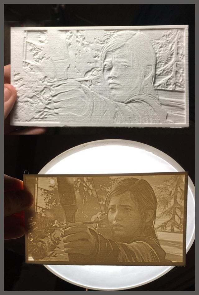
ZBrush provides designers with incredible feature capabilities, however those features equate to thousands of tiny polygons that aren’t always feasible for 3D printing. To ensure your part is producible and that its details resolve as desired, download the Decimation Master Plugin from ZBrush.
The Decimation Master Plugin will allow you to optimize the polygon mesh of your part for printing by specifying a percentage of the poly mesh to preserve for export. It will preserve detail while reducing poly count. For a quick overview of the plugin, including masking to preserve areas where high poly count is critical for your model, click here.
Once you have optimized your part using the above steps, it is ready to export as an STL file.
- Download the 3D Print Exporter Plugin from ZBrush
- Select the ZPlugin menu
- Click 3D Print Exporter
- Define and scale your dimensions
- Select STL > STL Export
- Save
Maya
You can also just load your native CAD into our online quoting tool to get instant pricing!
Maya is a free-form design space not specifically tailored to production, therefore it is especially crucial to check the dimensions and producibility of your design (are the wall thicknesses defined? Are all vertices connected?).
Check features for producibility:
- Window > Settings > Preferences >Settings
- Change measurement units to millimeters
- Review dimensions and scale within the Chanel Box
- Finally, open Create > Scene Assembly
- Access measurement tools to check all feature sizes and thicknesses
Once you’ve checked your part for producibility, open the Rebuild Surface Options and define the surface density of your part. This will determine the resolution of the final 3D print. Check the design guidelines of your preferred technology to ensure the 3D print process can handle your desired resolution. Design guidelines on each 3D printing technology can be found here.
Now you’re ready to export.
- Select File > Export Selection > Export as STL_DCE.
How Do You Make & Create STL Files for 3D Printing – Simple Guide – 3D Printerly
When you are in the field of 3D printing, there are steps you have to follow to be able to actually 3D print your objects. Many steps are done for you but making 3D printer files is one of the most important ones.
This article will show you exactly how 3D printer files are made so read on if you’d like to know.
3D printer files are made by using Computer Aided Model (CAD) software which allows you to create what your model will look like. After your model is complete, you need to ‘slice’ your CAD file in a slicer program, the most popular being Cura. After your model is sliced, it will be ready for 3D printing.
Once you understand the steps of this process and do it for yourself, it all becomes very easy and clear. I will do my best to detail the step-by-step process on how beginners create 3D printer files.
Creating models for 3D printing and learning how to make your own 3D model is a great skill to learn, so let’s get right into it.
- Choose & open a CAD program
- Create a design or model using the tools in your chosen program
- Save & export your completed design to your computer (STL file)
- Choose a slicer program – Cura for beginners
- Open & ‘Slice’ your file with your desired settings into a G-Code File
Choose & Open a CAD Program
There are many CAD programs out there that can be used to create your model, but some are definitely more tiered towards beginners which is what I’ll focus on in this article.
Also, many higher level programs actually need to be purchased, so you’ll be happy to know everything I recommend will be completely free.
The best CAD programs for beginners are:
- TinkerCAD – click and create your own account
- Blender
- Fusion 360
- Sketch Up
- FreeCAD
- Onshape
Check out my article Best Free 3D Printing Software – CAD, Slicers & More.
The one that I will focus on and do recommend is TinkerCAD for beginners because it was definitely designed for you guys in mind. Beginners don’t want a complicated CAD program that takes a while getting used to, they want to be able to put something together in the first 5 minutes and see its capabilities.
One of the great features of TinkerCAD is the fact that it’s browser-based so you don’t have to install some huge program file to get started. Just go to TinkerCAD, create an account, go through the short tutorial on the platform and get to modeling.
Once you get the hang of one CAD program and the way designing a model works, you can move onto other programs, but at first just stick to one simple program.
TinkerCAD has enough capabilities to keep you modeling there for at least a few months, before you think about moving to a software with more features. For now, it will work wonders!
Create A Design Using the Tools in Your Chosen Program
TinkerCAD specializes in ease of use, as you put together blocks and shapes to gradually build a more complex structure that you can be proud of. The video below will show you a quick tutorial on exactly how it looks and how it’s done.
It’s always best to follow a video tutorial when learning how to create designs, while doing the same thing in the program yourself.
Reading a guide of some sort is great when you understand the program and are looking for ways to do cool, new things but when just starting out, get the experience behind you.
Once you’ve created some of your own models by following a tutorial, a good point to go to next is to play around in the program and get creative. One thing I chose to do is find a few household objects and try to model it as best as I could.
This ranged from cups, bottles, small boxes, vitamin containers, anything really. If you want to get really accurate, you can get a sweet pair of Calipers from Amazon.
If you want a quick, cheap but reliable set I’d recommend the Sangabery Digital Caliper.
It has four measuring modes, two unit conversion & zero setting function. You can get very accurate readings with this device, so I do recommend you getting one if you don’t already. Also comes with two spare batteries!
If you want a higher quality Caliper, go for the Rexbeti Stainless Steel Digital Caliper.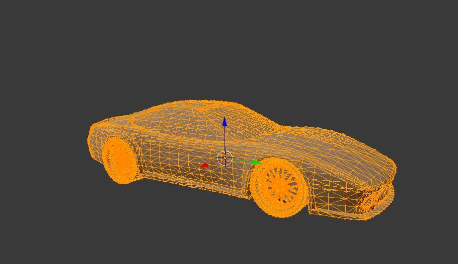 It is more premium with a polished finish and a case to hold the device. It comes with IP54 water & dust protection, has 0.02mm accuracy and is great for the long-run.
Once you get some good practice creating different items, you’ll be a lot more prepared to start making useful and complex 3D printer files.
At first, it seems like all these simple shapes and holes won’t be able to make much. This is what I thought at first before seeing what people could really create in this software.
The following was made on TinkerCAD by Delta666 found on MyMiniFactory. It would be hard to describe this as a simple design, which just goes to show you the potential you could have with designing your own 3D printer files.
Save & Export Your Completed Design to Your Computer (STL File)
The great thing about TinkerCAD is how it’s made for things to be easy to use. This also includes saving and exporting your STL files straight to your computer.
Unlike some downloaded CAD software, this one auto-saves your work each change you make so you don’t have to worry about losing your work.
As long as you have named your work in the top left, it should continue to save. You’ll see a small message saying ‘All Changes Saved’ so you know if it’s working.
As you can see in the picture, exporting your CAD files into a downloadable STL file is a piece of cake. Simply click the ‘Export’ button in the top right of your TinkerCAD page and a box will pop up with a few options.
When it comes to 3D printing files, the most common ones we see are the .STL files. There are a few things that people say it’s abbreviated from such as Stereolithography, Standard Triangle Language and Standard Tessellation Language. Either way, we just know it works pretty good!
The complex part behind STL files is that they are made up of several tiny triangles, with more detailed parts having more triangles. The reason behind this is 3D printers can better understand this information with this simple geometric shape.
Below is a clear illustration of these triangles making up a model.
Choose a Slicer Program – Cura for Beginners
If you’re in the 3D printing field, you either would have come across Cura by Ultimaker or are already well-versed in the program. Cura is the most popular, cross-platform slicing software that 3D printer hobbyists use to prepare their files for 3D printing.
There isn’t much point trying to go with another slicer because this one works so well and does exactly what you need it to do. It’s very beginner-friendly and doesn’t take long at all to get the hang of it.
There are other slicer programs out there, some even dedicated to specific 3D printers like PrusaSlicer or ChiTuBox. They all essentially do the same thing but Cura is the choice I recommend.
Check out my article Best Slicer for the Ender 3 (Pro/V2/S1), which also goes for other 3D printers as well.
Open & ‘Slice’ Your File With Your Desired Settings Into a G-Code File
The term ‘slice’ your file is one that is widely used in the 3D printing field which means to prepare your CAD model and turn it into a G-code file which 3D printers can make use of.
G-code is basically a series of commands that tell your 3D printer what to do, from movement, to temperatures, to fan speed.
When you slice your file, there is a certain function where you can preview your model in its 3D printing form. This is where you view each layer of your 3D print from the ground, up and you can even see the direction your print head will go while in the printing process.
It really isn’t as complicated as it looks. All it really takes is looking over the settings and hitting the blue ‘Slice’ button on the bottom right of the program. The box to the top right shows a simplified way to change settings without getting into all the specific settings.
It’s a spice rack in case you’re wondering!There are many settings in your slicer you can take control of such as:
- Print speed
- Nozzle temperature
- Bed temperature
- Retraction settings
- Print order prioritization
- Cooling fan settings
- Infill percentage
- Infill pattern
Now just because it isn’t complicated to get started doesn’t it mean it can’t get as complicated as you’d like it. I’m sure there are settings that Cura experts have never thought about touching.
This really is a short list when you have seen just how many settings there are, but luckily, you don’t have to worry about most of the settings. Cura has default ‘profiles’ which give you a list of already done for you settings that you can input.
This profile usually works great by itself, but it can take a little tweaking on the nozzle & bed temperature before you get some great prints.
There is a cool menu which allows users to choose custom setting views for beginners to masters, down to custom so the functionality and ease of use is great.
After you follow all these steps, you’ll have created your 3D printer file which your printer can understand. Once I’ve sliced a model, I simply get my USB drive and micro SD card which came with my Ender 3, plug it into my laptop and select the ‘Save to Removable Device’ button and Voilà!
I hope these steps were easy to follow and help you get started making your own 3D printer files.
It’s an amazing skill being able to design your own objects from start to finish, so try your best to stick with it and become an expert in the future.
If you found this helpful, I have other similar posts like the 25 Best 3D Printer Upgrades/Improvements You Can Get Done & 8 Ways How to Speed Up Your 3D Printer Without Losing Quality so feel free to check them out and happy printing!
STL format and 3D printing
Categories
- News list
- STL format and 3D printing
Description and features of the STL format
Today, the STL format (simulation file for stereolithography) is becoming increasingly popular. Its development was carried out for the needs of stereolithography (volumetric lithography), and was intended for rapid prototyping and visualization of three-dimensional models. The format describes the triangles that make up the outlines of any object. Its main difference from other formats is ease of use. To represent the shape of a digital 3D STL model, a sequence of triangles is applied.
There are two structures of STL formats: text and binary. The binary structure of the STL file of the model is more compact, requires less space, and has greater accuracy. But the use of a text structure allows the transfer of files to a computer with a different representation of numbers, and the number of characters for each number can be arbitrary. At the beginning of the text file of the STL program, the keyword "solid" must be present. The following is a brief explanation about the object and its manufacturer. Then the triangles themselves are described, for which unit normal vectors and a Cartesian three-dimensional coordinate system are used. The end of the file is marked "endsolid".
Converting to STL format
When meeting with STL, many people ask how to open this format. Your best bet is to use the Microsoft Internet Information Services (IIS) program. There are several other programs: MeshLab, Geomagic Explorer, Dassault Systemes CATIA and others. To edit the STL format, any 3D editors and CAD programs are used. 3D printing is taking us to a new reality, but in order to print anything, any 3D printer needs instructions. There are STL files for this.
All STL models for the printer include hundreds or even thousands of horizontal layers that will overlap until the 3D object is printed. Typically, such files are either written from scratch on their own, or ready-made ones are used, created using various 3D modeling programs. If you have not yet mastered the construction of three-dimensional objects with the nuances of conversion, it is easier to turn to ready-made 3D models. To do this, there are several free services on the Internet, such as: thingiverse.com., kraftwurx.com. and others.
Errors in the STL file
Your 3D printer will print the proposed material without any problems, but to get a high-quality result, you need to take into account one more small feature of the technology. When you export for printing, selected or created models in STL format, holes often appear on them, preventing the models from becoming solid. To avoid these problems, use the NetFabb cloud server. Send the file to it, and when it is fixed, check it with the STLView viewer, and only then resort to printing. We wish you success!
'; } html += '
'; html += '
' + json[i]['label'] + '
'; html += '
' + json[i]['special'] + '
'; if(json[i]['special']){ html += '
' + json[i]['price'] + '
'; } else { html += '
' + json[i]['price'] + '
'; } html += '
3D printing STL files: step by step guide - 3DPrinter
3D printing STL files: step by step guide in additive technologies. Information about an object is stored as a list of triangular faces that describe its surface, and their normals. The STL file can be text (ASCII) or binary.
 It got its name from the abbreviation of the term “Stereolithography”, since it was originally used in this particular 3D printing technology.
All modern CAD (Computer Aided Design) programs allow you to export your own file format to STL. The 3D model is then converted into machine language (G-code) through a process called "slicing" and the model is then ready to be printed.
In this article, you will learn the basic steps required to properly export your models for 3D printing .
Step 1: Resolution STL
The STL file format uses a series of linked triangles to recreate the surface geometry of a solid model. Increasing the resolution will use more triangles, better approximating the surfaces of the 3D model, but also increasing the size of the STL file.
If you export the file at too low a resolution, the model will have visible triangles on its surface when printed. In most cases this is not desirable, but they can be used to create "low poly" models with a digital look.
Increasing the resolution above a certain point is also not recommended, as it does not bring any additional benefit: very small details cannot be 3D printed, so the file size will be increased unnecessarily, making subsequent processing difficult.
Step 2: Export Options
You can change the resolution of STL files by changing the format options in the software. If you're unsure, choosing preset is the safest option to create an STL file that fits 3D print .
Each CAD package has different STL resolution options, but most use two main parameters: chord height and angle.
Chord Height is the maximum distance between the surface of the original 3D model and the surface of the STL file that the software can use. Using a lower chord height will help show the curvature of the surface more accurately.
The recommended value for the chord height is 1/20 of the thickness of the 3D printed layer and not less than 0. 001 mm (1 micron). This will always produce an STL file with perfect accuracy for most applications 3D printing . Exporting at a lower tolerance will not affect print quality, as most conventional 3D printers are not capable of reproducing such a high level of detail.
Angular tolerance limits the angle between the normals of neighboring triangles. The default value is often 15 degrees. Some programs also specify this tolerance as a value between 0 and 1. If a smoother surface does not require a higher setting, the default value of 15 degrees (or 0) is recommended.
Step 3: Export STL files from your CAD software
Let's see how you can quickly and easily convert your file to STL format in different programs.
AutoCAD:
Important: Export to STL format is only possible for entire 3D objects
- Enter “FACETRES” on the command line
- Set parameter FACETRES to 10.
- Enter command “STLOUT”
- Specify objects to export
- Press Y or Enter at the Create a binary STL file? [Yes/No]
- Specify file name
- Save the file.
Autodesk 3ds Max (3D Studio Max)
- Open the File > Export tab)
- Select file type - StereoLitho *.stl
- Enter file name
- Save file
- Select type Binary
- Press OK
Autodesk Inventor / Mechanical Desktop
Important: you can export both individual parts and whole parts of the model
- Open Manage tab > Update panel > Rebuild All
- Then open File > Save as > Save Copy As
- Select STL file format
- Enter file name
- Set the following parameters: Format - binary (Format > Binary), units - mm or inches (Units > mm, inches), resolution - high (Resolution > High)
- Save file
Google Sketchup
If you are using Sketchup Standard and not Pro, you will need to install a special extension to export to STL. You can find the appropriate extension for your version of Sketchup here. Download the extension, go to Sketchup > Window > Preferences > Extensions > Install Extension to install it.
To export to STL after installing the extension, follow the instructions below:
- Go to Sketchup > Tools > Export to DXF or STL
- Select the desired object to export. If you do not select an object, then the model will be exported completely.
- Select the units of measurement for the exported object: meters, centimeters, milimeters, inches, feet
- Select the geometry of the exported object: polyface mesh, polylines, triangular mesh, lines, stl
- Select where you prefer to save the exported file.
Attention: if you export a circle with this plug-in, then when you view it in some other programs, you will notice that when you increase it, it consists of short segments.
Blender
- Go to File > Export > STL
- Enter file name
- Specify file locations
- Press the Export STL button
Pro ENGINEER
- Open File > Save a Copy
- Select STL type and press OK
- Set Coordinate System Standard
- Select file format Binary
- Set the following parameters Chord Height to 0 (set the minimum allowable Pro/E values)
- Angle Control leave default
- Enter file name and press OK
Rhino
- Open the File > Export Selected or File > Save As tabs
- Select objects to export
- Set file type to Stereolithography (*.
 stl)
stl) - Enter file name
- Save file
- In the STL Mesh Export Options window, set the Enter Tolerance to 0.02 mm (0.0008 inches), then click OK.
- Set file format to Binary
- Uncheck the Uncheck Export Open Objects option
- And press OK again
Solidworks
- Go to File > Save As…
- Set the file type to STL(*.stl)
- Open the Options tab
- Set the output file format to Binary
- Units - millimeters or inches (Unit: > Millimeters or Inches)
- Resolution-Good (Resolution > Fine)
- Press OK
- Enter file name
- Save
SolidWorks Student Design Kit
- Go to File > Save As…
- Set file type eDrawings(*.eprt)
- Open the Options tab
- Check the box Allow export to STL for Parts & Assemblies
- Press OK
- Enter file name
- Save file
- Open the file in eDrawings
- Open the tabs File > Save as… > and set the file type to STL (*.
Learn more