Ciclop 3d scanner camera upgrade
Ciclop based Laser Scanner — FabScanPi documentation
1. About Ciclop
2. Bill of Materials
The following list shows what you need to modify the Ciclop scanner for using the FabScanPi Software.
General components
- 12V to 5V switching regulator
- Raspberry Pi 3 B+ or higher
- Raspberry Pi camera V2
- Raspberry Pi Camera Connection Cable - 50cm
- Micro SD Card ( >= 8GB)
- Silent Step Stick Motor driver
- 3D printed Camera Mount
- 3D printed Raspberry Pi Mount
3. Ciclop Modification
Mounting Raspberry Camera
You can use a printed camera mount to mount the Raspberry Pi Camera to the ciclop. The Raspberry Pi Camera will replace the USB webcam.
Note
The Raspberry Pi camera has a better image quality than the ciclop USB webcam.
Replacing the Motor driver
It is recommended to replace the default motor driver of the ciclop with a silent step stick driver. You can use a TMC2100, TMC2208 or TMC2009. But you need to configure the TMC2xxx driver to run in 1/16 micro stepping mode. If you decided to use the TMC2100 driver all you need to do is removing the jumpers under the ciclop motor driver. For other TMC drivers read the manual at watterotts TMC guide.
The motor driver which was included in the kit has a red or green surface.
The picture shows a TMC2100 motor driver on the ciclop Arduino Shield.
Note
You can also use the default driver, but the usage of a TMC motor driver lets the turntable move much more silent and smooth. That leads you to much better calibration and scan results.
Connecting Raspberry Pi
Connect the Ciclop Arduino USB cable to the USB port of the Raspberry Pi. Then connect the Raspberry Pi camera ribbon cable to the Raspberry Pi.
Note
You can use a Raspberry Pi camera ribbon cable extension (50 cm).
You can use a Ethernet cable for Network connection or configure the Raspberry Pi’s wifi setting-up-wifi.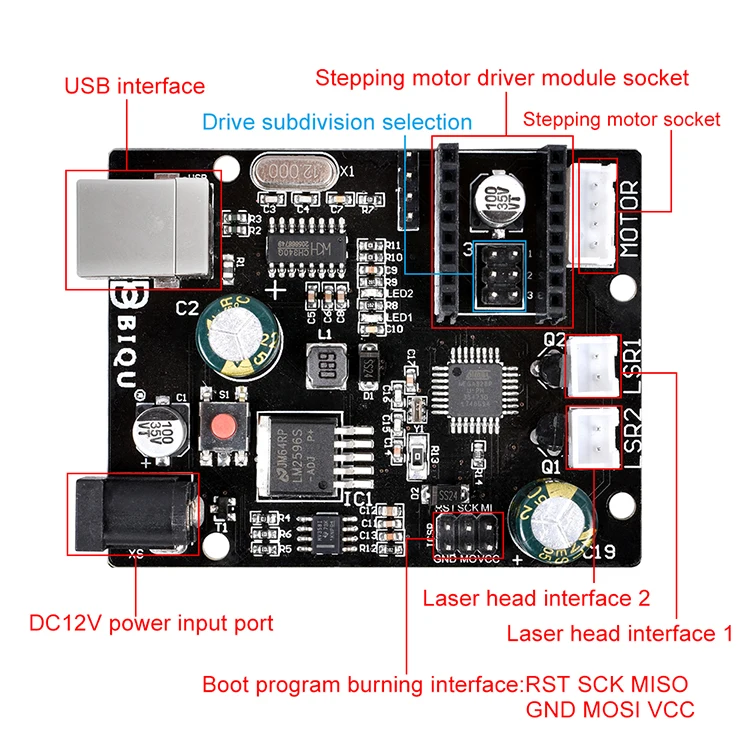
Warning
The Raspberry Pi 4 needs active cooling by a fan. Otherwise the scan process will stuck or fail.
Proceed with the Power Management.
The Power Management
The fastest way is using two power supplies. One 5V supply for the Raspbbery Pi and a second one with 12V connected to the Arduino for the motors.
Warning
Do not use the 5V supplied by the Arduino, because it does not supply enough current. The Arduino and even the Raspberry Pi may be demaged otherwise.
But if you want a setup with less wires, you should add a Step-Down converter like on the picture below.
The 5V output of the Step-Down converter is connected to the 5V and GND pin of the Raspberry Pi.
Connecting LEDs (WS2812)
It is recommended to connect a WS2812 LED-Ring or some WS2812 LED stripes for a better illumination of the object. You can use the 6 pin header on the original ciclop ZUM board.
5. Software Installation
Now you need to install the FabScan sotware.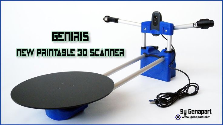 Please follow the Guide for Installing the Software.
6. Software Configuration
The image installation from the previous step already contains a default configuration for the FabScan. But some values need to be adjusted, depending on your hardware setup. You should recap your motor type, and the number of lasers at this point.
Note
If you don’t know how to edit a file by using a text editor on a Raspberry Pi console, you should read detailed chapter on How to Edit the Config File first..
Motor Config
You should be sure that the number of steps matches your motor. If you are using a NEMA17 motor, the common number of steps for a full revolution is 200 (1.8 degree per step). The motor driver is set to 1/16 step what results in 16*200=3200 steps. Most of the ciclop kits come with a 200 steps stepper motor.
Warning
It is important to set a correct value for your motor. A incorrect value can cause double/mirrored looking scans results. Even the calibration process might fail.
The example below shows a configuration for a 200 step stepper motor. The cilop turntable radius is 100mm. If you are using another turntable than the default one, change the radius.
"turntable": { "steps": 3200 "radius": 100, "height": 155 } Laser Config
Change the number of lasers to a number which matches your setup. If you are using just one laser then change numbers to 1, otherwise numbers should be 2. And be sure that interleaved is set to true.
"laser": { "interleaved": "True", "numbers": 2, "color": "R (RGB)" } Serial Connection
Be sure that the connector type is serial and the firmware is set to ciclop. The port should match the serial port where the ciclop board is connected. Mostly the port is /dev/ttyUSB0. The baudrate should be set to 14400 for the ciclop.
"connector": { "type": "serial", "firmware": "ciclop", "baudrate": 14400, "autoflash": "True", "port": "/dev/ttyUSB0", "flash_baudrate": 115200 } Calibration config
You need to change the calibration board config to the ciclop calibration board values.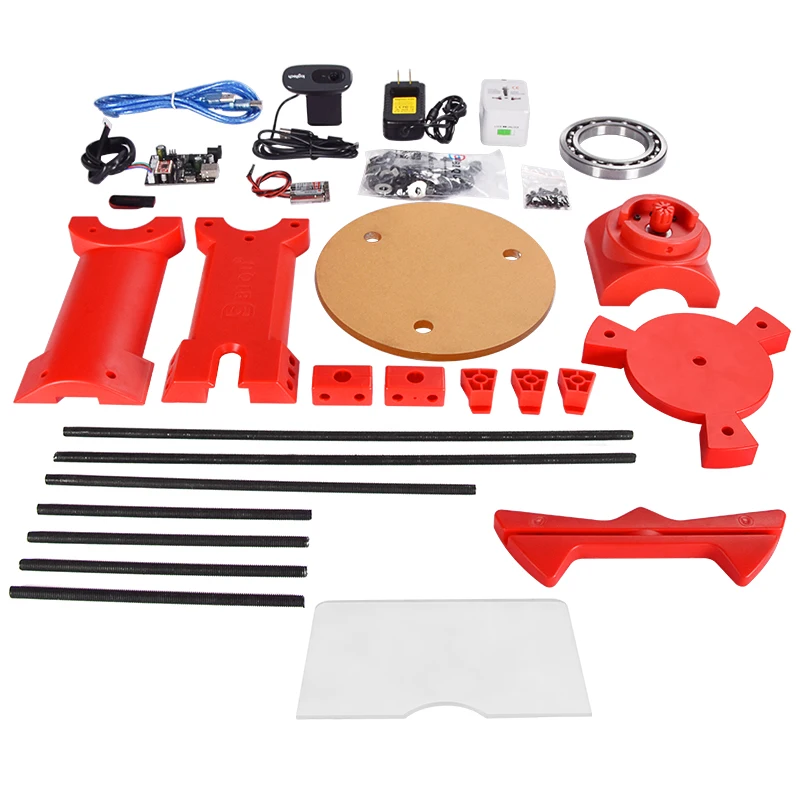
"pattern": { "square_size": 13, "rows": 6, "columns": 10, "origin_distance": 35 }, Note
Read more about the calibration configuration in the advanced Advanced Configurations section.
Leave the rest of the file as it is.
7. Using the Software
You can proceed with the software First Steps with the Software . A more complete software manual can be found in the section Software User Manual. Don’t miss to read the section about Calibrating the Software.
Note
A precise calibration is the key for good scan results!
assembling electronic and wiring – 3 – Renzo Mischianti
by Renzo Mischianti · Published · Updated
Spread the love
Support forum
After assembling the basic mechanical components it is now time to assemble and connect all the electronic parts.
Ciclop 3D scanner electronic assemblyThe original documentation is lost, so I grab the old material from the net and I translate and rewrite in this article.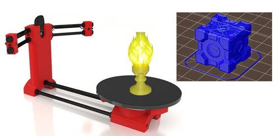
List of standard material to assembly
2 x Laser
1 x C270 Logitech® HD Webcam
1 x bq ZUM BT-328 controller board
1 x bq ZUM SCAN Power Shield
1 x Stepstick Drivers A4988 4 layers
2 x Laser cable duct printed part: 80 mm
1 x Printed part motor cable duct: 240 mm
1 x Printed part electronic cap
1 x Micro-USB Cable
1 x Power supply 12 V 1.5 A
1 x Methacrylate front pattern
1 x Printed part pattern holder
1 x Checkerboard pattern sticker
2 x Screw M3 x 10 mm – DIN 912 class 8.8 black
2 x Nut M3 – DIN 934 class 8 black
Introduce lasers
Ciclop 3D scanner Introduce lasers parts- Assembled structure
- Laser
- Allen wrench
Prepare the camera
Logitech c270 on AliExpress
Ciclop 3D scanner prepare the camera parts- C270 Logitech® HD Webcam
- Allen wrench
Fit the camera
Ciclop 3D scanner fit the camera parts- C270 Logitech® HD Webcam without Add-ons
- Main part assembled
Fit electronics: bq ZUM BT-328 + ZUM SCAN
You can find BQ ZUM Driver Board here Aliexpress
Stepper drivers on AliExpress
Ciclop 3D scanner Fit electronics ZUM BT 328 SCAN parts- Bq ZUM SCAN power shield
- Controller board bq ZUM BT-328
- Stepstick Drivers A4988 4 layers
- Main assembled parts
Fit electronics: my PCB
Ciclop 3D scanner PCB v12 photo prospective frontYou can get full instruction for my open source PCB (fully ZUM compatible) on the previous article.
You can order 10 PCB at PCBWay for few dollars here.
Ciclop 3D scanner board v1.2 PCBWay
Cable connection and routing
Back cover
Laser wireway
Motor wireway
Power supply on Aliexpress 12v
Ciclop 3D scanner parts for cable connection and routing- Printed part for laser cable duct and motor cable duct
- Printed part electronic cover
- Micro-USB cable
- Power supply 12 V 1.5 A
- Main part assembled
Mounting the calibration pattern
Pattern holder
Pattern surface
Pattern image to print
Ciclop 3D scanner parts for mounting calibration pattern- Methacrylate front pattern
- Checkerboard Sticker
- Printed part pattern support
- Nut M3
- M3 x 10 mm screw
- Allen wrench
Assembling video
Thanks
- Ciclop 3D scanner: component printing and assembly
- Ciclop 3D scanner: production and assembly of the control PCB
- Ciclop 3D scanner: assembling electronic and wiring
- Ciclop 3D scanner: componens testing and calibration
Support forum
Spread the love
Tags: 3D Printer3D scannerArduinoCiclop 3D scanner
3D scanners Ciclop and Piclop
3D modeling
Subscribe to the author
Subscribe
Don't want
19
Two scanners with a similar ideology, but different hardware and software solutions. Probably the easiest way to scan a model is to place it on a turntable, illuminate it at an angle with a laser pointer with a cylindrical lens that turns a point into a vertical line, film it with a camera, and calculate the offset of the line points from the vertical caused by the model.
About 3 years ago the idea was implemented in Spain by BQ labs and published under free licenses. Details of the design for printing on a 3D printer and a very beautiful horus program written in Python were posted. To clearly highlight the laser illumination, it was necessary to control the exposure of the camera. At the time of creation, Ubuntu 14.04 was up-to-date. V4L2 supports camera control, but it does not interface with the official version of OpenCV.
Following the principle of writing minimal custom code to get a workable result, the developers slightly tweaked the current version of OpenCV. The decision is correct, a working installation has been received, and whoever is late, let him clear up the situation in which installation on new versions of Ubuntu requires the demolition of all programs using newer versions of OpenCV.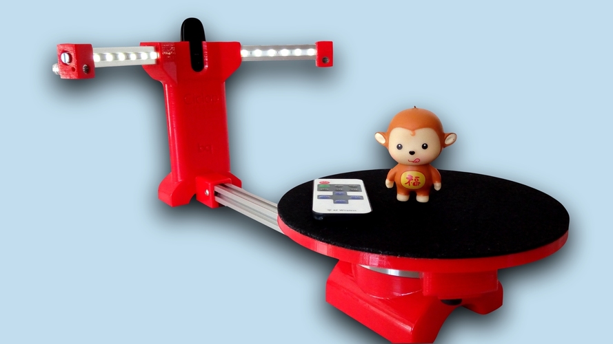 Ideologically, the system is outdated, and the authors. it was probably not interesting to edit subsequent versions, especially since this did not affect the mass consumer using Windows in their work, since this OS uses drivers from the camera manufacturer.
The community, of course, tried to solve the problem, but it seems that they did not achieve an ideal result that suits everyone. I followed the solutions suggested by Fabien Devaux. Its horus version does not require a special version of OpenCV, but is very slow. He proposed his own solution to this problem by writing a program thot with a CLI (Command line interface) command line interface. The program has its own automatic calibration system, but you can also use the calibration results obtained using horus.
I really liked the program, but automatic calibration is not my style :-). In the case of manual calibration, achieving a result is a matter of time and patience, and in the case of automatic calibration, it is always a lottery.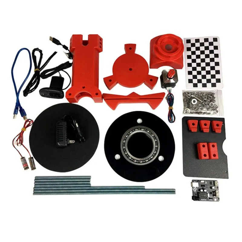 The Ciclop design is not well suited for calibration by moving the lasers and camera, although it is of course possible to tweak the automatically generated numbers to obtain an acceptable result with the existing arrangement of the design elements.
Therefore, having met on the net a description of the scanner on the Raspberry Pi camera (with which I am well acquainted) and requiring precise mechanical alignment of structural elements, I decided to repeat it. In this case, the freelss program, written in C ++, is used for control. Raspberry Pi cameras have very rich exposure controls, but this program does not use them, and uses adjustable lighting for fine adjustment.
At this stage, I did not change the program and decided to compare the capabilities of the scanners as if in their original form. Since I assembled my design exclusively from the available parts, some changes were made to the design, and compatibility with the source code of the program was achieved by introducing, generally speaking, an extra element on the Arduino computer.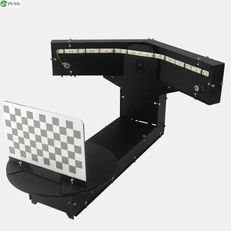
- My Piclop scanner design
- Scanning with freelss
- Scanning with horus
- Scanning with thot
- Processing
- MeshLab
- CloudCompare
- Summing up
Scanners achieve approximately the same result. The high resolution of the Piclop camera is not in demand, as is the ability to take more than 800 shots in one revolution. The perceived thickness of the laser beam limits the resolution. The perceived thickness of the line depends on the brightness of the point, which in turn depends on the reflectivity of the material of the model and the angle of incidence of the beam on the surface.
With the current laser beam extraction algorithm, reducing the line thickness due to better focusing or increasing the single threshold value will result in improved resolution for bright points and complete loss of information for darker ones.
Now we have a compromise that by limiting the resolution we get information about all points of the surface on which the laser beam fell.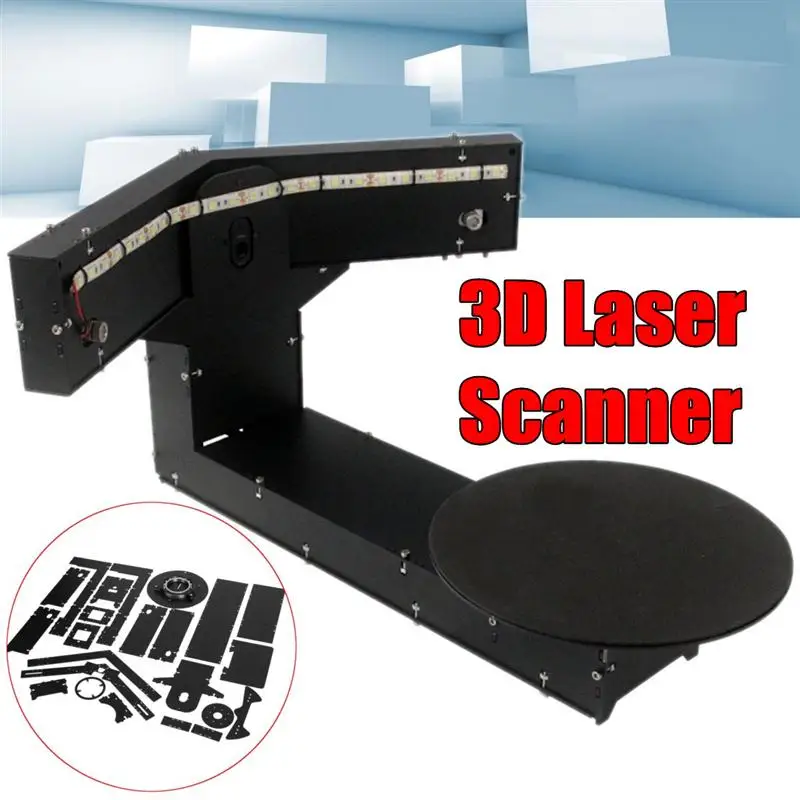 Potentially, for the Piclop scanner, you can write a program that, at high resolutions, will take several pictures with different exposures. However, this will increase the already not small scanning time with a resolution of 5 megapixels.
Aside from individual models with fine, subtle relief, a reasonable resolution for this scanner is 1.9 MP (1600 x 1200). At this resolution, the scanning speed for both scanners is about five minutes, but given the fewer final processing operations, the result from the Piclop scanner will be obtained a little faster.
I found it easier to achieve an acceptable result when scanning with two lasers on on a manually calibrated Piclop scanner. This is quite laborious, but patience and time allow you to achieve a result, while automatic calibration is a lottery, you may get lucky right away, you may never be lucky.
Follow author
Follow
Don't want
19
More interesting articles
25
Subscribe to the author
Subscribe
Don't want
At the beginning of September we released a new version of the KOMPAS-3D Home system for amateur 3D modeling.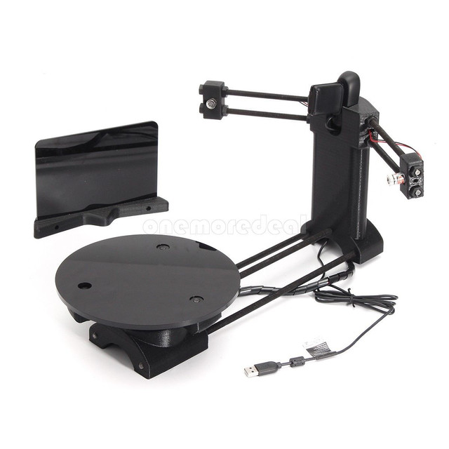 ..
..
Read more
XcLxAd
Loading
11/27/2022
2424
23
Subscribe to the author
Subscribe
Don't want
Once, in the life of every divers there comes a moment when chaos in the workplace begins to enrage.&n...
Read more
Sergey
Loading
03/16/2016
177251
264
Follow author
Follow
Don't want to
Hello everyone. The materialise website recently published an article in which they talked about public databases ...
Read more
Analysis of the BQ Ciclop 3D scanner 2 years after launch
At CES 2015 bq is presented by in the company of its bq CICLOP 3D scanner .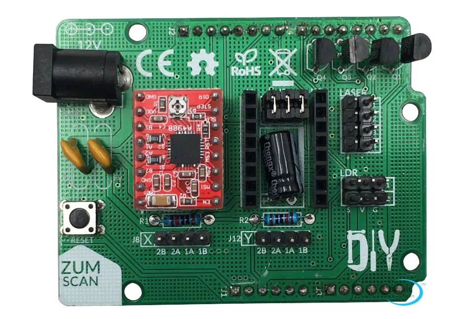 It was an open source project through which the company shared the work needed to develop the scanner with the entire developer community. In this way, users could collaborate on their ideas and improvements.
In this article we are going to analyze how this product has aged and if it is still useful to get a model with these characteristics.
Index
- 1 Technology used for 3D scanning
- 2 Features of 3D scanner BQ CICLOP
- 3 unpacking, assembly and installation of 3D scanner BQ CICLOP
- 4 Carefully
- 5 first scans
- 6 Price and distribution
- 7 Conclusion
Technology used for 3D scanning
Cyclops is a scanner based on 3D triangulation which includes a pair of lasers projecting two lines on a rotating object on a rotating platform. The camera captures both textures and shapes of the scanned object.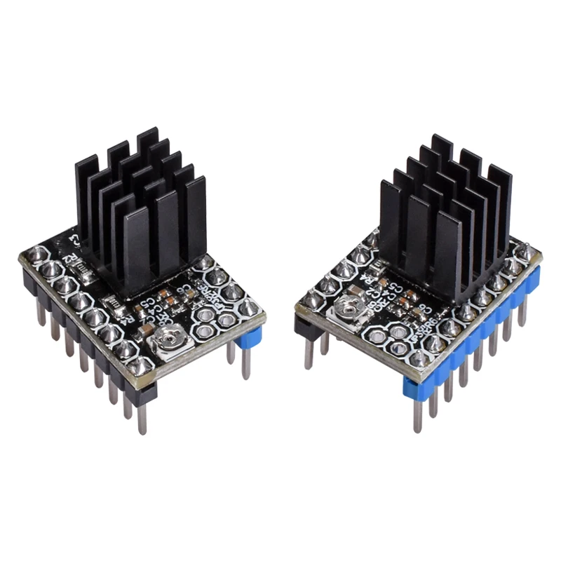
A black object receives a laser beam linear, which is deflected by reflection and captured by a sensor which transmits the position of each point of the detected beam to the reconstruction program and writes it to its database along with the rest to be able to form a complete three-dimensional image. As soon as the object changes its shape or position, the incident light is no longer reflected in the same way, thus it is not directed to the same area of the camera and therefore a different point is registered on the model to be scanned. ...
Be able to process all the received information through the camera and manage the options and parameters of the scanner, bq has developed Horus , a multi-platform and free application.
The BQ Ciclop 3D scanner allows the to scan objects up to 205 mm in diameter and 205 mm wide to resolution up to 500 µm in about 5 minutes.
La scanner electronics consists of Arduino based board, Logitech camera, 2 line lasers and stepper motor.
BQ Ciclop 3D Scanner Features
Maximum scan size: 205 mm (diameter) x 205 mm (height).
Optics / Sensor: Logitech C270 HD Camera 1280 x 960
Resolution: 500 µm
Scanner Dimensions: (x) 450 x (y) 330 x (z) 230 mm r) 205 x (h) 205 mm
Scanner weight: Approx. 2 kg
Scan accuracy: 500 µm
Scan speed: Approx. 3-4 min.
Steps per revolution: Between 1600 and 160
It seems that although a couple of years have passed since the launch of this product, the opportunities to purchase a device at a reasonable price have not increased, and Modern home scanners have almost the same functions as the bq model . .
Unpacking, assembly and installation of the BQ Ciclop 3D scanner
El installation very easy very well documented by the manufacturer.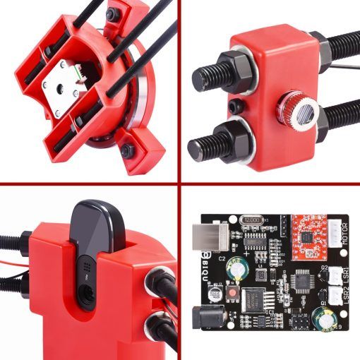 Depending on how qualified you are, following guide it may take from 30 minutes to hour for the equipment to be completely mounted. We finished it very quickly, without hesitation at any stage and without canceling any part due to misinterpretation of the manual.
The manufacturer even posted a video on YouTube. which in just 3 minutes shows in detail how we should place all the parts.
Although the product comes with manuals in different languages, we recommend that you go through web portal What do you have for your products? . at they posted everything you need to use your scanner. From manuals to the latest Horus software.
Careful
We always find it funny when we buy products with FDM printed parts. In the case of the scanner, , all plastic components are printed in PLA. It is difficult for a small company to resort to this practice, but it is hard for us to imagine that this process could be more profitable for a company like bq than making an injection mold.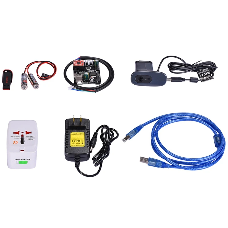 However, we can check that The print quality of these components is excellent .
For the correct operation of the scanner, you need to install the Horus software and the Logitech webcam drivers that includes the system, all this can be found on the manufacturer's web portal
for Arduino Firmware Update What includes. If we made our own scanner we can use any Arduino 9 board0124 which meets the manufacturer's specifications. A very revealing detail of a good job bq.
We have everything assembled and connected to the PC, it's time to install the software and perform the first scan.
The first problem we encountered is that due to the fact that different webcams were connected to the PC, Horus could not automatically determine which one to use, and the software could not clearly display the detected webcams. webcams. After a couple of attempts, we found a suitable webcam, nothing serious.
We can only scan surfaces or capture color using both lasers or just one.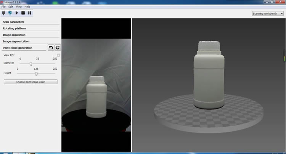 And there are endless options that we can customize to optimize the scan according to the characteristics of the environment in which we perform the scan.
First scans
Our first scan was a disaster, which, on the other hand, is completely logical, we started the scan without any considerations. Visiting manufacturer forums teaches us that the laser triangulation system is very sensitive to the fact that the intersection of the two lasers is perfectly aligned with the center of the turntable. . However, BQ has overlooked something as simple as the mark in the center of the platform. Square, compass, paper, pen and the problem is solved. After the calibration of the lasers, the quality of the scanned objects improved significantly.
When scanning an object, we get a grid of points that we can save in .ply format, but this file cannot be used on any printer, because the .stl format is usually used. Another visit to the manufacturer's website reveals that Horus program does not generate .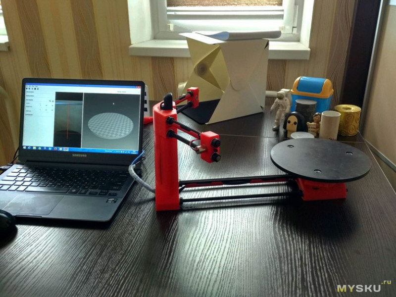 stl files, to achieve this format we have to use another open source program.
Having to use a second software to achieve the desired result makes using the scanner less round. However, bq has documented all the steps required to complete task .
In the image we see the scanned model and the resulting 3D image.
Based on the tests carried out, it can be argued that the results will be very different depending on the large number of variables . From the illumination of the area in which the scanner is located, the accuracy of the calibration performed, or even the colors that the scanned object contains.
One of the improvements recommended by the manufacturer: scan the object several times at different angles so that the dot grid has the least number of areas that the light from the laser beams cannot reach.
Price and distribution
Although this equipment has been on the market for 2 years and It is not on the manufacturer's own website.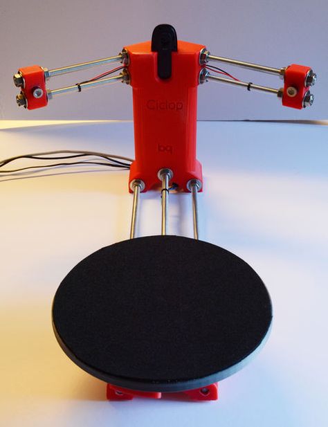
Learn more