Calibration 3d print
Top Ten Prints to Calibrate your 3D Printer
Get the most out of your 3D printer with these calibration tests which are designed to reveal small adjustments you can make to get your 3D prints to really shine.
MatterHackers
September 30, 2022
With this set of 3D models, you can fine-tune your 3D printer to optimize your it's capabilities and get the best 3D printed parts possible. Let's dive in!
Jump To:
- Vertical Surface Test
- Horizontal Finish Test
- Dimensional Accuracy Test
- Overhang Test
- Bridging Test
- Negative Space Test
- Retraction Performance Test
- Support Material Test
- Full Bed Dimensional Accuracy Test
- Z Wobble Test
- Squareness Test
- Download Calibration Models
Vertical Surface Test
This test is designed to look for "ghosting" or “ringing,” where features echo and ring out along vertical surfaces.
As the print head makes a quick movement, it can oscillate, which creates a ring effect. The oscillations diminish on longer lines and the vertical surfaces clear up until a sharp turn is made again. Ghosting can come from a lack of rigidity like a loosely mounted hotend or a wobbly frame, springy belts, printing at high speeds with a heavy direct-drive print head, a bed that isn't rigidly mounted, or firmware settings for acceleration or jerk that are too high for what the printer can achieve.
Some printers can handle high jerk and acceleration, where others will falter and show significant error because of it.
Vertical Surface Test
Horizontal Finish Test
With three different sections - flat, slope, and domed - you are able to see any sort of artifact or ridges from where the perimeters start and end. The more noticeable these points, the lower the score.
Cleaning this up depends on slice settings about perimeters, like start and end overlap, overlap percentage, and where the seam (start/end point of each outer perimeter) is located.
Horizontal Surface Test
Dimensional Accuracy Test
When you're printing coasters and keychains, it doesn't really matter if a part is 0. 2mm too wide, but for multi-part prints that need to fit together, the accuracy of each part is very important to keep things fitting properly. Slots for connector pieces can be just fine off of Printer A but too tight to use from Printer B, or holes for nuts and bolts are supposed to allow for easy installation, but require unnecessary force to assemble.
The second level of this pyramid is supposed to be 20mm wide and deep, and loses points based on the average deviation from 20mm; if the average deviation is between 0 and 0.1mm, a full 5 points is earned. If the deviation is between 0.1mm and 0.2mm, 4 points are earned, and so on.
If you get a bad score, you should run through a calibration sequence for your extruder, making sure that your e-steps are accurate. You can find a helpful guide on how to do that here.
Dimensional Accuracy Test
Overhang Test
This test is designed to see how well the printer can cool down the hot plastic as it is extruded; the better the cooling, the cleaner the bottom surface is. Printing speed does affect cooling, so the lower the print speed, the more time for freshly laid down filament to cool before the next layer is ready.
A small print with high print speeds is going to need much more cooling than a large print at slow speeds since material will have only a very brief amount of time to cool enough to solidify.
It is important to consider that the type of fan used for layer cooling (axial vs radial) and the direction your fan outlet is facing will impact how well an overhang is printed, so it would be wise to print this test rotated every 90 degrees to see if some faces fair better than others. You might even consider a new ducting for the cooling fan to try and direct the airflow toward the part.
Drooping, curling, and hanging filament all lower the score, especially when the lower angles have difficulty.
Overhang Test
Bridging Test
Most slicers have the ability to detect bridging, which is where filament needs to cross an unsupported span. Usually the slicer will turn up the layer cooling fan, slow down the print speed, and change how the this section is printed so the span is efficiently crossed with long strands rather than small zigzags.
This bridging test piece tests a bridging condition, but most models won’t have bridges this obvious or long. You can expect to see some minor bridging over holes in the side of a model, over grooves, or over slots for inset nuts.
You get 1 point for each clean bridge.
Bridging Test
Negative Space Test
Much like the dimensional accuracy test, it's important that negative space is accurately replicated. When you're trying to insert screws cleanly without drilling it out or threading the plastic, it's important to know how much extra space you need to model into your part to accommodate. In general, when I need to insert an M3 bolt, I'll model a 3.2mm hole to make sure it slides in easily.
In general, if you precisely calibrate the steps/mm for the extruder, start and end overlap, and seam alignment, you can push out all 5 pins without much force. If there's difficulty removing any of the pins, there’s still something that needs to be calibrated out to achieve tighter tolerances. One point is earned for every pin that can be pushed out.
Negative Space Test
Retraction Performance Test
This test is hard to quantify the difference between a 4 and a 5, but the main thing this is looking for is retraction optimization. This is one of the toughest slice settings to calibrate due to just how many factors affect retraction, like the number of retraction settings, and even things like layer cooling, print speed, extruder style, or even your extruder's ability to extrude and retract without chewing the filament.
Retraction Test
Support Material Test
Whether you're using a dedicated support material like PVA or HIPS or you're using a single extruder printer and using the same material as your support material, it's important to have your support settings calibrated. Same material supports are printed with what's called an "air gap" where the print head rises above the print to create a slight gap between the roof of the support and the bottom of the printed part, giving the filament extra time to cool and droop onto the supports, preventing them from permanently adhering to each other. That air gap is something that needs to be optimized; too small and the supports adhere to the finished print, too large and the bottom surface will be really stringy and droopy until it can recover.
Dedicated support materials produce a bottom surface finish almost as clean as the top surface, because they are printed without an air gap since they can be dissolved away. The test model has separate sections for intricate supporting and a flat bottom surface, because an air gap optimized for one may not be enough for the other.
Support Test
Full Bed Dimensional Accuracy Test
While the dimensional accuracy test checks the accuracy of a fairly small part, this test checks accuracy across the entire bed. A small error in the dimensional accuracy test will compound into a larger discrepancy across the bed, which is 10 times longer than the first test. The smallest difference in expected vs actual measurement just means that any multi-part prints are going to skew depending on the orientation the part was printed in.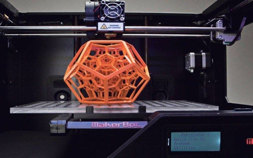
Full Bed Dimensional Accuracy Test
Z Wobble Test
Unlike every other test, which uses a scale to grade the proficiency of the 3D printer, this test is simply a pass or fail. The tower has a wide brim to make sure it is well adhered to the bed, and to ensure that any sort of issue in the walls of the tower comes from the printer's structure, and not because it tipped off of the bed. If there is any wobble, it should be cyclical and repeat with a period identical to the pitch of the lead screw attached to the Z axis. If the lead screw had an 8mm pitch, then you should see the pattern repeat every 8mm.
A key thing to watch out for is to make sure that your Z axis is properly constrained and not over constrained. Properly constrained means you have smooth rods, linear rails, or extrusions with V-slot wheels making sure that the Z axis only moves on Z and doesn't shift around. Rods, rails, and wheels should be tensioned or secured so that they don't wiggle or move when the Z axis is raising or lowering.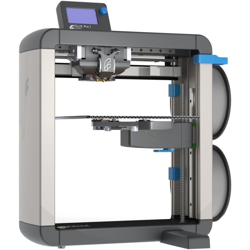 Over-constrained is something like installing bearings at the top of the leadscrews in a support bracket. This is actually counter intuitive, because no lead screw is perfectly straight and adding that bearing causes a deflection in the lead screw. There should in general only be two part interacting with the lead screw: a coupler that attaches it to a motor (or be part of the motor) and a lead screw nut, anything else is overconstraining it and can hurt print quality more than help.
Z Wobble Test
Squareness Test
This test was developed to make sure that the printer's X and Y axis are assembled square with each other; this test will determine if the printhead moves on X, does it move a marginal amount on Y as well, or vice versa. Using an angle gauge, you will measure each of the five squares and determine how far off each corner is from 90 degrees. The further off from 90, the lower the printer's score.
Squareness Test
These are the top ten .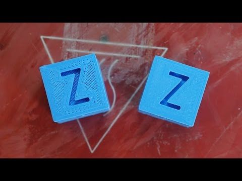 ..really 11 prints because there's just no way to cut out any one of these, they all serve a very specific purpose that without them you're missing some element of troubleshooting and calibrating your 3d printer to perform at its absolute best. And these are the tests that we run to make sure that the printers that we work with are running at their best as well, so I hope that with these calibration prints you’re better equipped to help calibrate your own 3D printer and getting it to perform at the best that it absolutely can.
All of these calibration prints, collected by Make, can be found in one place on Thingiverse here:
https://www.thingiverse.com/thing:2755063
Happy calibrating!
20 Best & Most Popular 3D Printing Calibration Tests – 3D Printerly
When I first started 3D printing, I didn’t know much about calibration tests so I just went straight into 3D printing objects. After some experience in the field, I learned how important 3D printing calibration tests are.
The best 3D printing calibration tests include the 3DBenchy, XYZ Calibration Cube, Smart Compact Temperature Calibration, and the MINI All In One Test for configuring your 3D printer efficiently.
Keep reading through this article to learn what the most popular 3D printing calibration tests are, so you can improve your model quality and success rate.
The 3DBenchy is probably the most 3D printed object and most popular calibration test of all time, giving users a “torture test” that can be used to see how well a 3D printer can perform.
The goal is to 3D print a 3DBenchy that can successfully handle overhangs, bridging, inclines, small details, and dimensional accuracy. You can find the specific measurements of what your Benchy should measure up to on the 3DBenchy Measure page.
TeachingTech made a great video that goes over how to troubleshoot your 3DBenchy if it isn’t coming out perfect.
There is even a 3DBenchy Facebook Group where you can ask for advice and get some feedback about your Benchy.
One interesting tip that one user discovered is that you can check for under or over extrusion by sticking the chimney of one Benchy into the box of another Benchy.
The 3DBenchy was created by CreativeTools.
The XYZ Calibration Cube is a popular calibration test that helps you tune your 3D printer so it becomes more accurate and precise for making high-quality 3D prints.
The calibration cube has three axes: X, Y, and Z and the idea is that they should all measure 20mm when you print the cube. This can determine whether your 3D printer is creating dimensionally accurate objects or not.
If you happen to measure 19.50, 20.00, 20.50mm for the X, Y, and Z axes respectfully, then you can adjust your e-steps for the individual axis to get it closer to the 20mm measurement
The following video is a great tutorial on printing the XYZ Calibration Cube and how you should configure your 3D printer accordingly.
One user has pointed out that you should measure the cube at its top layers to get more accurate readings. This is because some inconsistencies can be caused by an uneven bed, so do make sure that your bed is properly leveled, and that you measure the cube at its top, just to be sure.
The XYZ Calibration Cube was created by iDig3Dprinting.
Cali Cat is the perfect alternative to regular calibration cubes and is a simple test that determines if your printer can handle advanced prints.
The Cali Cat model is equipped with the linear dimensioning tests of a calibration cube, making sure that you nail down the basics before moving on to complex prints.
Besides that, it has many complicated features as well, such as a 45° overhang, surface irregularities in the face, and bridging. If you see imperfections in your Cali Cat print and don’t observe high-quality features, then you have to configure your 3D printer.
The following is a great explanation of what the Cali Cat is and what role it plays.
Cali Cat or Calibration Cat takes about 30 minutes to print, so it is a quick and easy way of calibrating your 3D printer to get great quality parts reliably.
It can also serve as a cute desktop decoration for you, as many people have said. It’s definitely more fun to print than regular cubes or the 3DBenchy.
The Cali Cat was created by Dezign.
4. ctrlV – Test Your Printer v3
The ctrlV Printer Test V3 is an advanced calibration test that challenges the capabilities of your printer, to see just how well it can really perform.
It has several tests in one such as:
- Z-Height Check
- Warp Check
- Spike
- Hole in wall
- Raft Test
- Overhang tests (50° – 70°)
- Extrusion width tests (0.48mm & 0.4mm)
To get the best results with the V3 calibration test, you want to configure your slicer’s settings and retraction settings as well as level your bed properly. You’ll get better results with time using trial and error consistently.
One user pointed out that having the print bed heated to 40-60°, depending on your filament, can help get the model to stick properly and print successfully.
The v3 model takes somewhere around two hours to print, so it’s definitely one of the best calibration tests out there if you want to tune your 3D printer relatively quickly, compared to other models that take considerably longer.
The ctrlV Printer Test V3 was created by ctrlV.
The Smart Compact Temperature Calibration Tower is an effective test for determining the best temperature for your 3D printer filament. The “Smart” edition of the Temp Tower adds more features that you can use to configure your printer.
A temperature tower consists of many units, and each unit is printed at a different temperature, usually with increments of 5°C to find out the temperature that works best for your specific filament.
To print a temperature tower successfully, you have to implement a script in your slicer so the temperature changes automatically with each block of the tower.
Doing that can get confusing for beginners, so I highly recommend watching the following video that takes you through the process of how you should print the Smart Compact Calibration Tower.
Many people have said that the Smart Compact Temperature Calibration Tower has worked wonders and they were perfectly able to calibrate their printer, especially by using the video above.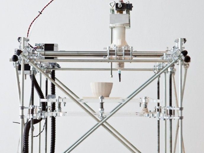
The Smart Compact Temperature Calibration Tower was created by gaaZolee.
The Ender 3 Calibration Files are pre-sliced G-code files for the Creality Ender 3 or any other Marlin-based 3D printer to help you find the ideal slicer settings.
This isn’t a calibration test specifically, although it does include a speed test for calibrating your printing speed. However, the pre-sliced G-code files included in this download can be really helpful for configuring your 3D printer.
The sliced files consist of the following:
- Retraction Test With and Without Automatic Bed Leveling
- Heat Tower With and Without Automatic Bed Leveling
- Speed Test With and Without Automatic Bed Leveling
- Fully Configured Ender 3 Simplify3D Profile
The following video by the creator of the Ender 3 Calibration Files is a good visual guide on how to tune your slicer settings.
The Ender 3 Calibration Files have been created by TeachingTech.
The Part Fitting Calibration test is for tuning your 3D printer’s extruder to make parts more size-accurate.
The goal is to print the S-Plugs of this test in such a way that they fit together perfectly. There’s also another model called Thin Wall Test under the “Thing Files” section for calibrating your Wall Thickness.
One interesting piece of information is that if you’re using Simplify3D, you can enable the “Allow single extrusion walls” setting under the “Thin Wall Behavior” section of the Advanced settings to print the Thin Wall model with the best results.
People who have successfully calibrated their extruder using this test say that objects like bearings, gears, nuts, and bolts now fit better and work as intended.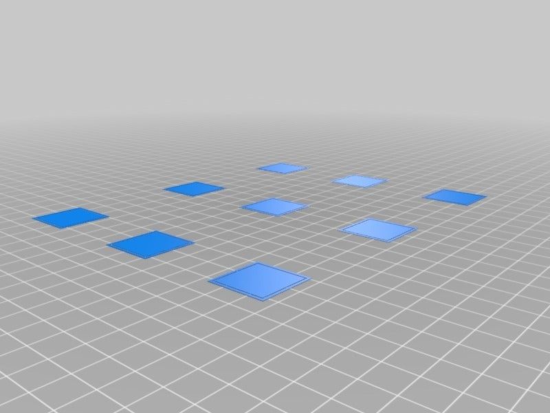
The Part Fitting Calibration was created by MEh5d.
The Retraction Test is a popular calibration model to check how well your 3D printer’s retraction settings are tuned.
The aim is to print the model and see if there is any stringing in the four pyramids. People say that this is a great calibration model for fixing stringing in your prints before moving on to more advanced objects.
The creator has left working settings for Slic3r software in the model description, such as:
- Retraction Length: 3.4mm
- Retraction Speed: 15mm/s
- Retraction After Layer Change: Enabled
- Wipe on Retraction: Enabled
- Layer Height: 0.2mm
- Print Speed: 20mm/s
- Travel Speed: 250mm/s
One user says that decreasing the temperature by 5°C has helped reduce stringing, since the filament doesn’t get as softened and retains it’s shape better. It’s advised to implement trial and error with your slicer’s settings until you find that sweet spot and make high-quality prints.
The Retraction Test was created by deltapenguin.
The Essential Calibration Set is a combination of multiple calibration prints that determine how well your 3D printer is configured as a whole.
This calibration test consists of the following models:
- .5mm Thin Wall
- 20mm Box
- 20mm Hollow Box
- 50mm Tower
- Perimeter Width/T Tester
- Precision Block
- Overhang Test
- Oozebane Test
- Bridge Test
The creator has left instructions for printing each calibration print that’s part of this set in the description. It’s worth following these to fully calibrate your 3D printer.
The Essential Calibration Test was created by coasterman.
The Ender 3 Level Test is a calibration method that uses a G-code command to help you level the print bed evenly and prints five 20mm discs for tuning your adhesion.
This calibration test works by instructing your 3D printer’s nozzle to move towards each corner of the print bed with a slight pause in-between.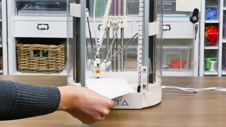 Doing so allows you to manually tighten or loosen the leveling knobs and level your 3D printer.
The G-code will instruct the nozzle to stop at each corner twice, so you can comfortably level the print bed of your Ender 3. After that’s done, a total of five 20mm discs will be printed for you to check adhesion: four in each corner, and one in the center.
Do bear in mind that this test is compatible with 3D printers that have a 220 x 220mm build volume. However, the model has been updated to include the G-code file for the Ender 3 V2 as well, which has a 235 x 235mm build volume.
The Ender 3 Level Test was created by elmerohueso.
The MINI All In One 3D Printer Test aims to target several parameters of a 3D print all at once to check how capable your 3D printer really is. It used to be a larger version but he updated it to be smaller and quicker to print.
This calibration model consists of a variety of different tests, such as:
- Overhang Test
- Bridging Test
- Support Test
- Diameter Test
- Scale Test
- Hole Test
The MINI edition of this object is 35% smaller than the original All In One 3D Printer Test.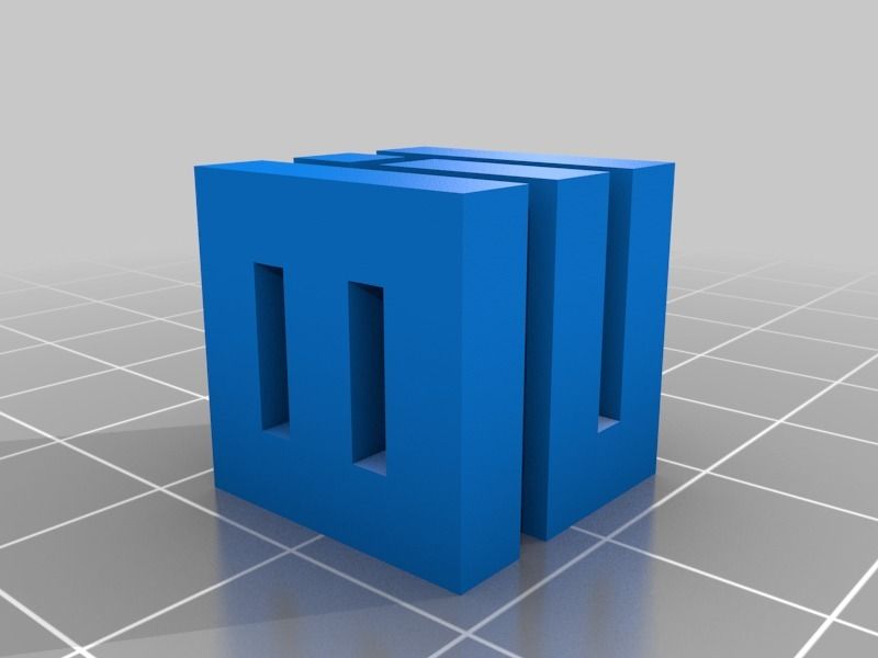 People have been really able to dial in the settings of their 3D printer after printing this model.
The results of this 3D printed test would allow you to check which areas of your 3D printer need work, so you can troubleshoot the shortcomings accordingly.
The following video is a nice illustration of how this calibration test is printed.
People advise printing this model with 100% infill and with no supports for the best results. There’s also a version of this model without the text under the “Thing Files” section that can also be tried out.
The creator made a guide to try and assist users who are experiencing any issues with the test. It goes through fixing over extrusion, PID auto-tuning, temperature settings, belt tension, and bed PID.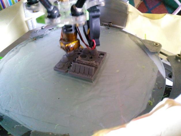
The Mini All In One was created by majda107.
The Lattice Cube Torture Test is the ultimate calibration model that tunes your 3D printer’s retraction, overhangs, temperature, and cooling.
This test is based on Maker’s Muse’s lattice cubes, but this one is more of a modification for your printer’s calibration.
You’ll find several different types of lattice cubes under the “Thing Files” section, each with its own features that are worth getting into.
For instance, the Super Lattice Cube STL is a complicated model that comprises two lattice cubes rotated together thereby making it even harder for your printer to get everything right.
The creator says that it’s best to keep your Layer Height to 0.2mm for the best results when printing the lattice cube.
The following video by Maker’s Muse is a great introduction to the lattice cube torture test so do give it a watch to find out more.
The Lattice Cube Torture Test was created by Lazerlord.
The Ultimate Extruder Calibration Test tunes your 3D printer’s ability to print bridges and gap distances by calibrating the temperature and travel speed.
Using this model, you will be able to see how far your bridges can reach without noticeable imperfections. If you find the bridges start sagging, it means that you need to lower the temperature.
In addition, there are large gaps within the model which is great for testing reversal or travel speed settings. It’s also recommended to set extra shells to 0 and use as little infill as possible to save time and print the model quicker.
People who have tried the Ultimate Extruder Calibration Test say that this is a very useful calibration print that has helped people get optimal temperature settings and make perfect bridges.
One user who printed the model said that reducing the gap fill speed in PrusaSlicer specifically leads to better stability during printing.
You can also customize this model using your own variables. For this purpose, the creator has left instructions in the page’s description that you can easily follow.
The Ultimate Extruder Calibration Test was created by Starno.
The Customizable 3D Tolerance Test tunes your printer’s accuracy and determines how much clearance is best for your 3D printer.
Tolerance in 3D printing is how accurate your 3D printed model matches the dimensions of the designed model. We want to minimize the amount of deviation as much as possible for the best results.
This is something that’s necessary to calibrate when you want to make parts that must fit together.
This model consists of 7 cylinders, each having its own specific tolerance. After printing the model, you will carefully examine which cylinders are stuck tight and which ones are loose.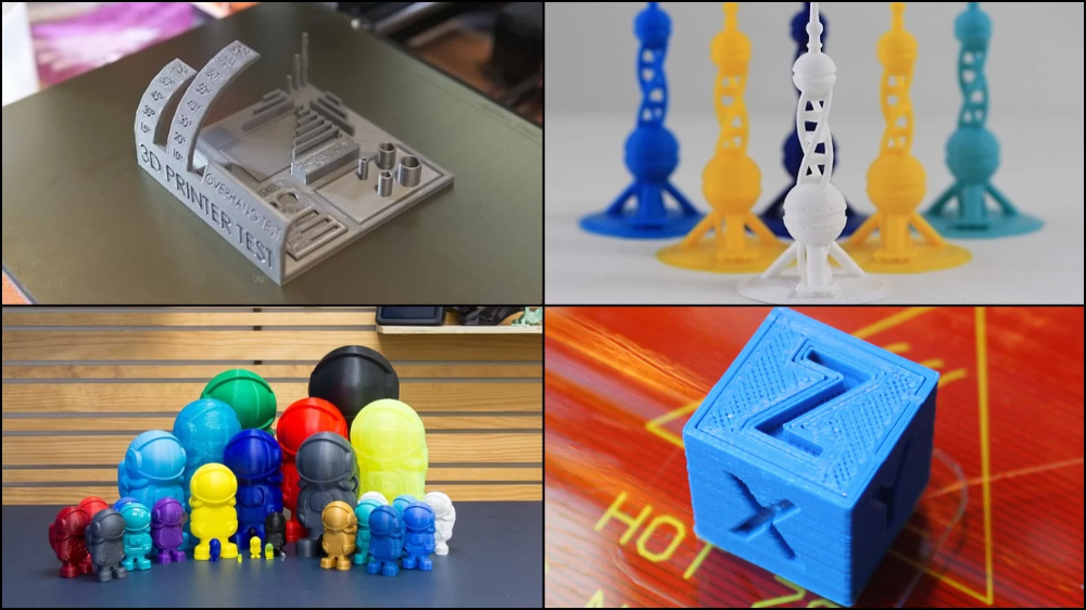
The ones that are loose can be easily taken out with a screwdriver. In this way, you can determine the best tolerance value for your 3D printer.
The following video by Maker’s Muse nicely explains what tolerance is and how you can test it for your 3D printer.
One user advises to print the model with 0% infill or else the whole model may get fused together. You can also use rafts with this print for better adhesion and to prevent warping.
The Customizable 3D Tolerance Test was created by zapta.
The Ultrafast and Economical Stringing Test is a quick and easy fix for stringing in your 3D prints that requires no extra post-processing steps.
This model gives you the advantage of stopping the print as soon as you observe stringing in the two pyramids that are printed. You can then tweak your retraction or temperature settings, and print another one of these models to continue the calibration.
If the issue still persists, I highly recommend checking out another one of my articles that discusses 5 Ways to Fix Stringing and Oozing in Your 3D Prints.
People who have tried calibrating their 3D printer with this model have shown a lot of appreciation for the creator. This model takes somewhere around 4 minutes to print and uses very little filament.
It saves you both time and money, and makes it possible to get rid of stringing in your parts, which is when the nozzle pushes out excess filament and leaves small strings of material on your print.
You can also watch the following video to get a visual idea of how to identify stringing and why retraction settings influence this imperfection among other factors.
It’s worth noting that keeping your filament dry is half the work for getting successful 3D prints. I’ve put together an ultimate guide on How to Dry Filament Like a Pro so do check that out for an in-depth tutorial.
The Ultrafast and Economical Stringing Test was created by s3sebastian.
The Bed Center Calibration Test recenters your print bed and helps you change the bed center that your 3D printer recognizes, to the actual center of the bed.
Printing this model will allow you to clearly see whether your print bed is perfectly centered or not, and this is something that’s necessary to make parts without being offset from the center.
The cross feature in the model should be exactly in the middle of your print bed and the distance from the outer squares to the edge of the heated bed should be equal.
If you find your bed away from the center, you will need to measure the offset in the X and Y direction and change the bed center value in your firmware to calibrate the print bed.
The following video on bed centering goes in-depth in this process, so you should definitely check it out.
The Bed Center Calibration Test was created by 0scar.
The Lithophane Calibration Test model is a simple test for that helps you determine the best print settings for 3D printed Lithophanes. It has a set of wall thickness values that increase by 0.4mm, with the first 0.5mm value being the exception.
Here are the recommended settings that the creator has left for the model:
- Walls Count 10 (or 4.0mm) – or higher
- No Infill
- 0.1mm Layer Height
- Use a Brim
- Print Speed 40mm or less.
This model has a 40x40mm and 80x80mm version, with three types for each size:
- STD which includes a combination of raised and recessed numbers
- RAISED which only contains raised numbers
- BLANK which has no numbers
The creator recommends that using either the RAISED or BLANK model for printing the Lithophane Calibration Test is better for achieving the desired results, so do implement trial and error to calibrate your 3D printer.
The Lithopane Calibration Test was created by stikako.
The LEGO Calibration Cube is similar to a regular calibration cube for testing print tolerances, surface quality, and slicer profiles, but these can be stacked upon each other, making for a more visually pleasing and useful calibration cube.
This model serves the same function as the XYZ Calibration Cube, but can be seen as an upgrade since it can even be used as a cool display or toys.
Ideally, you should be having a 20mm measurement on all three axes of the cube, which you measure with a set of Digital Calipers.
If not, you can calibrate your e-steps for each axis separately to fine-tune your 3D printer and get back to making high-quality prints.
People love the idea of the LEGO Calibration Cube because it not only allows them to configure their printer but also beautifies their desktop as the cubes are stackable.
The Lego Calibration Cube was created by EnginEli.
The Flow Rate Calibration Method is an effective test that helps you calibrate the flow rate using trial and error, so your 3D printer extrudes the correct amount of filament.
This calibration test is a quick and easy way of tuning your flow rate, which is essential for getting high-quality prints. However, make sure that your e-steps are calibrated before you test your flow rate.
That said, here’s how you easily calibrate your flow rate with this model.
Step 1. Download the Flow Rate Calibration STL file that matches your nozzle diameter.
Step 2. Print the model with your Flow Rate set to 100%.
Step 3. Measure the width of each wall of the printed model.
Step 4. Take the average of your measurement using the (A/B)*F formula. The resulting value will be your new Flow Rate.
- A = expected measurement of the model
- B = actual measurement of the model
- F = new flow rate value
Step 5. Print the model again with the calibrated Flow Rate value and measure the model afterward. If the actual measurement is equal to the expected one, you’ve successfully calibrated your Flow Rate.
If not, calculate the Flow Rate again with the measured value and repeat the process until the two measurements match each other.
The following video is for those who prefer a visual tutorial.
The Flow Rate Calibration Method was created by petrzmax.
The Surface Finish Calibration Test determines how well your 3D printer prints the surfaces of your models. It’s perfect if you are having problems with 3D printing uneven or curved surfaces, so you can calibrate your printer correctly beforehand before starting the main model.
This model is a quick and easy way to print multiple surfaces and check them each. Doing so makes it simpler to tweak your slicer’s settings and calibrate your 3D printer.
You can check out the recommended settings in the page’s description for each resolution of the model.
The creator also mentions that if you live in a humid area, decreasing the nozzle temperature by 5-10°C can help you get better results.
The Surface Finish Calibration Test was created by whpthomas.
3D Printer Calibration / Sudo Null IT News
Sometimes the owner of a 3D printer has to do this. I will tell the habr-community about my method. Please note that the manual is detailed, but leads to excellent results - the model adheres perfectly and does not peel off during the printing process.
To begin with, I would like to note that I honed my skills on the SmartCore Aluminum printer purchased here.
Installing the heating platform
The heating (or non-heating, depending on the printer) platform must first be set in height. To do this, there is a limit switch for the Z axis.
From Wikipedia:
A limit switch is an electrical device used in control systems as a sensor that generates a signal when a certain event occurs, usually mechanical contact of a pair of moving mechanisms.
This trailer can be adjusted in height by means of a tightening bolt and clamping bolt.
It is necessary to set it so that the surface of the platform clearly touches the extruder nozzle.
For further calibration, we will use Pronterface from the Printrun software package.
The advantage of this package is the visual and convenient control of the nozzle and printer platform, but if someone is more comfortable using Repsnapper, it is also quite suitable. Cura is not suitable for calibration, for lack of the necessary functionality for this.
To continue, let's make sure that when you press the "Home" button (white house is shown), the platform rises and rests closely, but does not try to move further towards the nozzle.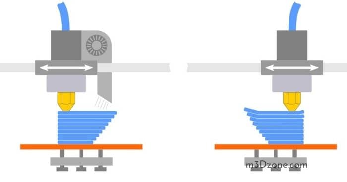
Since the firmware on my printer was taken directly from the SmartCore Aluminum repository (albeit not directly from Marlin), the nozzle goes to the middle of the platform. If this is not the case for you, and the nozzle remains in the corner at zero coordinates, it's okay, this is not important for further calibration.
Calibration
The following steps must be carried out in turn on the center, corners and reference circle:
- If the corner rests against the nozzle (the center should rest, as we achieved by adjusting the height of the limit switch during preparation), then we slightly press the platform bolt at this corner until a minimum clearance appears.
- We eliminate the minimum clearance, but no more. Ideally, we should have a nozzle that is clearly butt in all corners and in the center when you click on the Z-axis calibration. This is the result we need to achieve for high-quality printing, more on monitoring the result later.
- Now you need to make sure that when you click on , a gap will appear. If this does not happen, you can slightly release the bolt that presses this corner and, by successively pressing the green house, then the “0.1” button, repeat until the desired result is obtained.
After we finished the calibration at all five points and went through them so that we didn't have to change anything, we can proceed to check the calibration result.
Test
For testing, I use a simple model drawn in FreeCAD and gcoded in Cura. Plastic, the more accurate the diameter, the better - I take it here because of the declared accuracy and variety of colors. However, for verification, we will use the natural color of ABS plastic.
The meaning of a simple little test model is probably clear - saving money and time.
It is in this sequence that it makes sense to check. However, if you are confident in your calibration, then you can immediately start with step 2. Well, if you already have experience and you are absolutely sure of your calibration, then you can immediately go to step 3 - print 5pad.gcode.
The difference is in the number and arrangement of products.
I will describe the verification of the first step, since the rest are similar.
Suppose one side of the platform is too highly calibrated. It is very easy to find the result:
Top view:
And what is more important for us now is the bottom view:
- this is what the Cura rim looks like if the nozzle is located too high to the platform. Plastic does not fall accurately, sometimes clinging to neighboring lines.
Consider the opposite situation - if the nozzle is too pressed against the platform:
As you can see, not everything is smooth here either, the plastic, trying to fill the available space, will fit on adjacent lines, and on the next layer, the nozzle re-clings and smears again over the available space. However, it should be noted that in this case the model sticks very well, and the calibration defect is not visible on the next layers. Moreover, it may not even be noticeable at all if you choose a substrate in Cura for sticking the model to the table.
Finally, the desired and correct result:
Here you see a slight burning, but it is associated with an uncleaned piece of thread, which is clearly visible in the photo of the bottom view. Similar burns are rather inherent in the previous case, when the nozzle is too pressed. And the rest - smooth lines, tightly laid. That's the way it should be. Congratulations - the center point calibration is successful.
It is normal if such a result is obtained on glass at a temperature of 100 degrees. At the same time, if the glass is degreased and even, then after the end of the calibration, it will not come off during the printing process. You can try peeling the part off the heated bed after printing. Until it cools down to 90-80 degrees, you might not even be able to do it without damaging the glass. Also, the absence of a draft may be important, which affects the equally important uniformity of heating of the platform surface.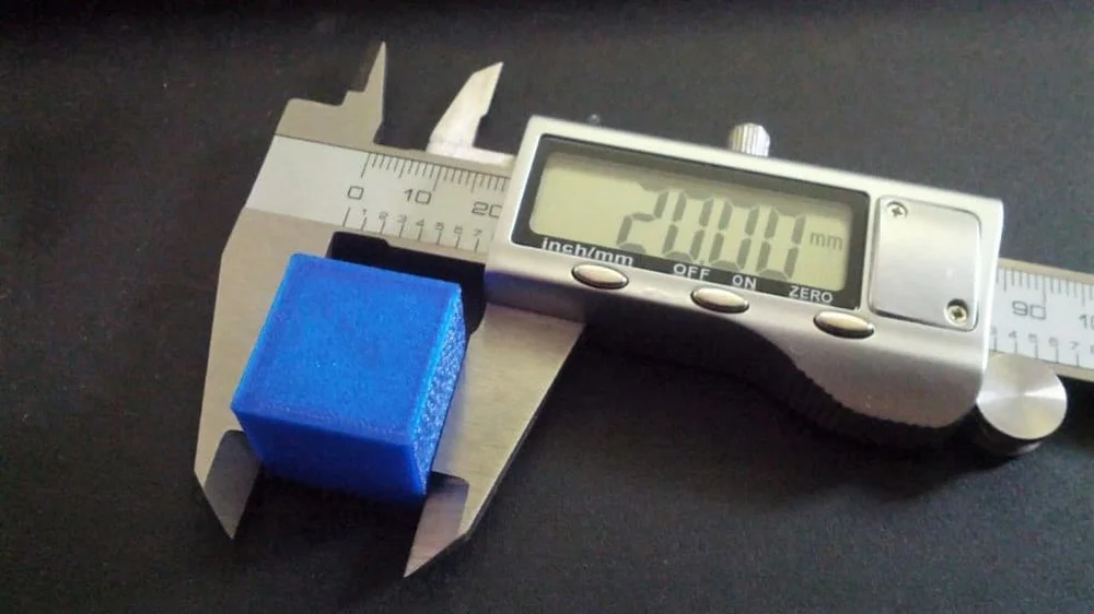
Here are general photos for easy comparison:
Top view:
Bottom view:
Further verification is similar in essence, but 4pad.gcode should be printed - covers a slightly larger central area. And 5pad.gcode - will show the quality of the calibration in the corners.
Happy calibration everyone!
At the end of the entertaining video, which shows the enjoyment of the result:
As you can see, I'm not printing on glass, but more on that in the next article.
How to calibrate the table correctly, and why the "paper" method doesn't really work
3D printing
to destroy the firmly established myth that the level of the table must be adjusted using a sheet of paper.
Yes, I know that many people do this, and it even works for them - no, it doesn't work, because physics is still a bitch. :)
everyone does it this way
To begin with, let's analyze what happens with the classic adjustment of the table level with a piece of paper: how much?) pressed a sheet of paper, repeated in all corners of the table.
what is wrong?
And it's not true that you hit zero on the Z axis!
A sheet of paper has a thickness of 0.15-0.25 mm (you measured it, right?), and by setting the level of the table in this way, you not only did it by eye, because the paper tends to sag under load, but also the gap between the nozzle and table made do not understand what.
what threatens?
And when the printer starts printing, say, with a layer of 0.2 mm, it will start counting from your unrealistic zero, and instead of the distance between the nozzle and the table expected by the printer, it will get the layer height plus the thickness of the sheet of paper!
Hello dear delamination!
Now imagine printing with a layer of 0.15 or even 0.1 mm?
You will have a gap between the nozzle and the table three to four times the thickness of the layer!
Please don't make trouble for yourself out of the blue. :)
:)
Z-axis zero is zero - the nozzle touches the table! And nothing else is given!
how to set it up correctly?
- throw away the paper and buy a 0.2 mm dipstick (or a set of dipsticks) at the auto shop
- manually, through the slicer or the printer menu, raise (lower) the table to a height of 0.2 mm, i.e. thickness of the probe
- align all four corners of the table with the thumbs so that the probe fits snugly into the gap between the nozzle and the table. It touched the lower part of the nozzle with its surface, but did not touch its side surface
That's it - the table is leveled and the actual zero on the Z axis coincides with the printer's expectation.
The plastic lays down as it should be, the adhesion improves dramatically.
What about the gap? We need clearance! Doesn't work without it!!!111
Need a gap - make it for a specific print.
And that's all for me, I wish everyone a clean print.


