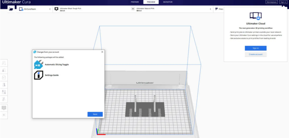
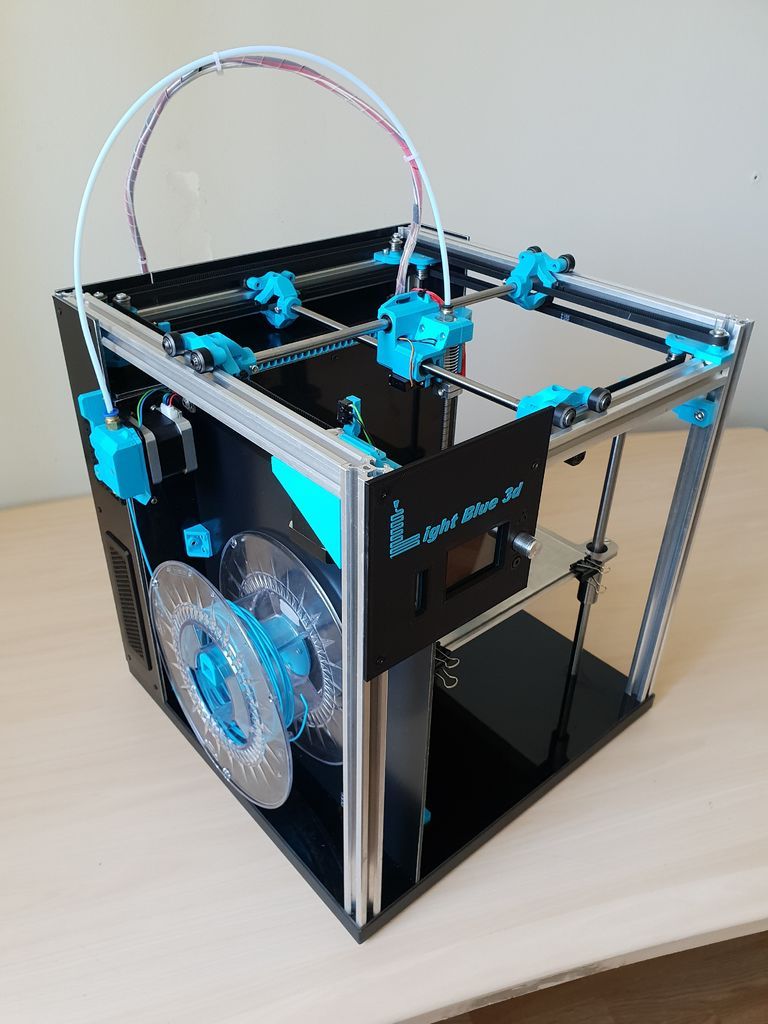
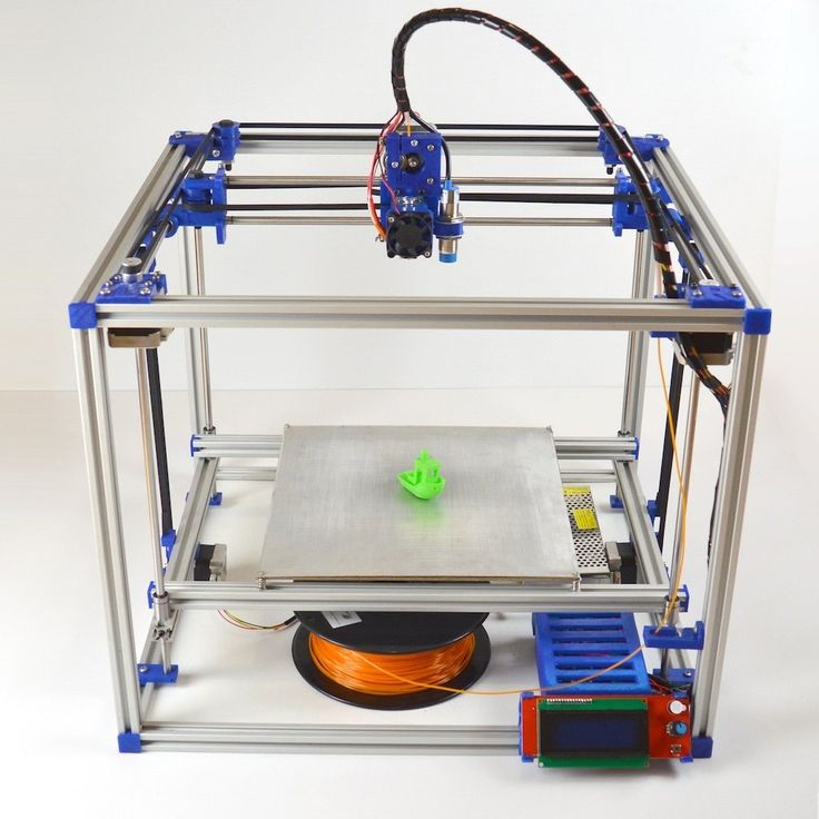
3D printer network connection
Network 3D Printer with Windows 10 IoT Core - Windows IoT
Edit
Twitter LinkedIn Facebook Email
- Article
- 2 minutes to read
Turn your Windows 10 IoT Core device into a print server and connect your 3D Printer to it. You will be able to access your printer wirelessly from other devices.
1. Install Windows 10 IoT Core on your device
Before you start, you will need:
A board with the latest version of Windows 10 IoT Core Insider Preview installed. Follow the Get Started guide to get the IoT Dashboard app and install Windows 10 IoT Core.
A 3D Printer compatible with our Network 3D Printer app:
- Lulzbot Taz 6
- Makergear M2
- Printrbot Play, Plus and Simple
- Prusa i3 Mk2
- Ultimaker Original and Original+
- Ultimaker 2 and 2+
- Ultimaker 2 Extended and Extended+
- CraftBot 2
- CraftBot PLUS
- LulzBot Mini
- Velleman K8200
2. Connect your 3D Printer to your device
3. Deploy the Network 3D Printer app
In IoT Dashboard, click on the Try some samples section.
Select the Network 3D Printer sample app.
Select your 3D Printer model and press the Deploy and run button to deploy the app to your IoT Core device.
LulzBot TAZ 6 image by Aleph Objects, Inc. is licensed under CC BY-SA 4.0.
If you wish to install a custom printer select the "Custom" option from the list of Printers. Custom 3d Printers need a configuration xml called the PrintDeviceCapabilities.xml file to be provided to correctly connect and print to the 3d printer. A sample PrintDeviceCapabilities.xml file can be found in Sample configuration XML
The minimum changes you need to make in the xml file are to update the following sections with the correct values specific to your compatible printer.
These values specify the print bed dimensions of your 3d printer to the slicer when processing the 3d model
<psk3d:Job3DOutputAreaWidth>200000</psk3d:Job3DOutputAreaWidth> <psk3d:Job3DOutputAreaDepth>200000</psk3d:Job3DOutputAreaDepth> <psk3d:Job3DOutputAreaHeight>200000</psk3d:Job3DOutputAreaHeight>
The value in the psk3dx:baudrate xml tag controls the specific baud rate to use while communicating with the 3d printer from the raspberry pi3.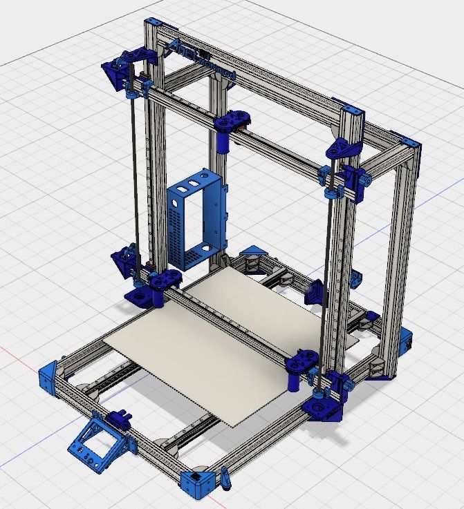 Set the appropriate baud rate specific to your 3d printer.
\<psk3dx:baudrate\>115200</psk3dx:baudrate>
The other values in the PrintDeviceCapabilities xml are used to notify the slicer in the 3d print driver to fine tune how it works with your specific compatible printer. More information on all these values are provided here.
4. Add your 3D Printer
Go to your Windows 10 PC and go to Settings -> Devices -> Printers & Scanners.
Press Add a printer or scanner.
Select your 3D Printer and press Add device. The printer will install automatically.
Congratulations your printer is now installed and will behave exactly as if it was connected with a USB cable. You can now print to it using 3D Builder.
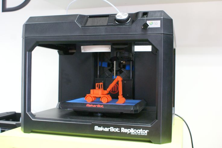
How to Connect Your 3D Printer to Your Computer or Laptop – 3D Printerly
Connecting your 3D printer to your laptop or computer is a task that many people want to get done, but they just don’t know exactly how it works. This article will change that for the better, giving you clear instructions on how to get it done properly.
3D printers come with so many connection technologies like Wi-Fi and USB. Using them can be difficult for some. With this guide, we’ll help you make things easier.
In this article, we will show you different ways to link your 3Dprinter to your PC. We’ll take you through each method step by step and answer your troubleshooting questions.
So, stick around, there’s a wealth of useful information in this article that will be sure to help you.
Should You Connect Your 3D Printer to Your PC?
Most people 3D print using a simple SD card with their files on it, but connecting to your PC is ideal in some cases. It can offer significant advantages with more control over your 3D printer. An SD card does make 3D printing easier, but requires more of a manual input.
I would personally recommend going the SD card route.
There are some advantages and disadvantages to each method.
Advantages to Connecting Your 3D Printer to Your Computer
- Easily send commands from your computer to your 3D printer to set settings and more
- Directly 3D print files from your computer, so you don’t have to go through the manual transfer of files
- Some 3D printers that give limited access to their settings like the Ender 5 Plus, so this can overcome it
- Easier to update firmware quicker on your 3D printer
- Greater control over the print in real-time, with monitoring capabilities
Disadvantages to Connecting Your 3D Printer To Your Computer
- A sudden shutdown or even your computer going to sleep can lead to a print disruption
- Set up can be tricky, especially to beginners since it goes into firmware and driver changes
- Using an SD card or internal memory can offer advantages in transmission speed and stability
How to Connect Your 3D Printer to Your Computer or Laptop
So if you’ve decided to link your computer to your PC there are different ways you can go about that. The sort of connection you can use depends on the sort of port configuration that comes with your printer.
Most printers come with an SD port and a standard USB A port. Recently, newer model 3D printers have started using wireless connections like conventional printers. With some further configurations and settings, even older models without Wi-Fi capabilities can now enjoy wireless capabilities.
USB, Wi-Fi, and USB proxies like OctoPrint are the preferred methods for connecting to PCs. Let’s take you through how these work.
USB Connection From Your 3D Printer to Computer
This is still the most popular method. USB remains the default configuration on most printers, so this is the logical choice for most users. Although variations can exist between different brands, the connection process largely remains the same.
What Do You Need to Connect Your 3D Printer to a Computer?
- Your 3D printer
- Your computer
- A USB cable that has the right connection to the 3D printer (usually a Type A)
- The relevant software, drivers, and firmware updates if needed
Let’s take you through how you can use a USB to connect your printer to your PC.
Step 1: Check the ports
- Before connecting the cables, it’s best to check if the ports on both devices, especially the PC, are functioning properly. You can use a tool like a mouse to check it.
Step 2: Connect the devices
- You can do this with standard USB Type-A wire that come in the box with the printer.
- It’s best to use short thick cords. These cords provide the highest data quality.
- Great data quality is needed to prevent interruptions during printing.
Step 3: Install device drivers.
- USB devices nowadays are mostly plug and play. Just plug in the device and watch the drivers install automatically.
- In some cases, the drivers might come in a disk or a drive, and you might need to install it manually.
Step 4: Install the printer control software.
- After installing the required drivers, you might need to install the printer’s software that comes with it.
- The printer’s software can come with the printer, or you might need to download it from the manufacturer’s website. Repetier-Host and Pronterface are good software that many people use.
- Open the device software and follow the manufacturer’s settings for proper configuration.
And just like that, your printer is ready to use.
The video below is a great tutorial using the Pronterface software.
When going through all these steps and installing the necessary software, sometimes there may be unexpected glitches. We have compiled some of the frequently encountered glitches and their solutions.
Wi-Fi Connection From Your 3D Printer to Computer
To set up 3D printing via Wi-Fi, you need:
- A wireless-capable 3D printer
- A home wireless network/ router
- A wireless-capable PC
With a Wi-Fi capable 3D printer, you should have specific instructions to take you through the process to connect things up.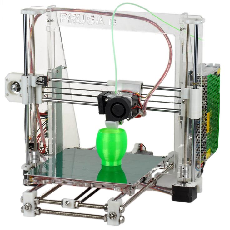 With my Anycubic Photon Mono X, the Wi-Fi setup was fairly basic to follow, though it has limited functionality.
Other 3D printers with Wi-Fi functionality usually have many benefits and control so I’d definitely look out for those.
(Note: On some printers without a LED display, you need to connect the printer to the PC via USB initially to be able to connect to the Wi-Fi network.)
Step 1: Power up the printer, router, and PC
Step 2: Install the printer, software, or firmware on the PC
Step 3: Connect the PC and the 3D printer to the router
Step 4: Click on the connected device on the PC and select the printer from the list.
Step 5: Open the printer software and configure the printer
Step 6: Send your models to the printer for printing
You can choose to use something like the Creality Wi-Fi Box to start a Wi-Fi connection to your 3D printer. The video below by Teaching Tech is a walkthrough and review of this product.
Connecting Your 3D Printer Wirelessly With OctoPrint
Octoprint is a great way to connect your 3D printer to your computer. It began as a way to print remotely for 3D printers without wi-fi capabilities.
Over time, it has evolved into a brilliant application that not only offers remote monitoring from various devices but also includes multiple plugins that extend the functionality of basic 3D printers.
Octoprint consists of an Arduino board with a wireless connection and a web-based interface for controlling the printer. It serves as a USB proxy for 3d printers without wireless connection capabilities.
Setting up OctoPrint can be a little difficult, but with a little elbow grease, it can be done. Let us show you how:
What do you need;
- A PC with wireless capabilities.
- A wireless network.
- A Raspberry Pi with a Wi-Fi adapter.
- An SD card for the Raspberry Pi (8GB minimum).
- A USB cord for the printer.
How to get it done:
Step 1: Download and install the OctoPrint Software with Etcher.
- Download the OctoPrint image here.
- Download and configure the Etcher software.
- Insert the SD card in the PC and follow the instructions here to flash and configure the Octoprint image to the SD card using Etcher.
- Configure the wireless settings using settings found here.
Step 2: Configure the Raspberry Pi
- Insert the SD card with the OctoPrint image into the Raspberry Pi.

- Connect the Wi-Fi adapter to the Pi and power it on.
- Access OctoPi from your PC by connecting to http://octopi.local.
- Follow the first run instructions and create a username and password.
- Logout and disconnect the Raspberry Pi from the power supply.
Step 3: Connect the printer to the Raspberry Pi.
- Using a standard USB A cord, connect the printer to the Raspberry Pi.
- Power on the Raspberry Pi.
- Connect to the web interface with the http://octopi.local.
You should be able to print from the web interface now.
Fixing Issues With a USB Connection From 3D Printer to USB
Failed Initialization
Sometimes, there might be communication issues between the printer and the PC. The PC might fail to recognize the printer and not display it on the device manager. To fix this:
- Check the USB ports and the USB cord in use for faults. Replace the cord if necessary.
- Reboot both the printer and the PC and try reconnecting them.
Failed Driver Installation
Many problems can occur during driver installation, due to issues like maybe outdated OS or a botched installation. There are many ways these issues can be solved, let’s go through some of them.
Method 1: Using the device manager.
You can use the device manager on Windows to search for the drivers.
- Search for the device manager in the windows search box and click on it.
- Look for the printer, it should be there with a yellow sign near it that indicates a driver issue. If the printer is not there, then check your connection.
- Right-click on the printer and select update/install drivers from the drop-down list.
- The PC will search the internet for the appropriate drivers and install them.
Method 2: Manually Installing the drivers.
In case the first method doesn’t work, you might need to download and install the driver manually.
- Arduino drivers are some of the most commonly used drivers for 3D printers.
- Download the Arduino IDE drivers here.
- Follow the installation guide here and install them on your PC
Software Problem
The software included in the box may be non-responsive or buggy. Sometimes printer manufacturers don’t even offer print control software. Here are some tips to solve these problems.
Method 1: Troubleshooting the software
- You can try rebooting the PC and checking all the connections to make sure there’s nothing wrong there.
- Reinstalling the software is always a great way to solve issues.
- Check the manufacturer’s website for updates and support if the following steps do not work.
If the software problems persist after that, it’s time to consider third-party software. There are a lot of third party printing software that work with a wide range of 3D printers. A great example is Repetier-Host.
You can download it here and follow the installation and configuration guide here.
New features of PICASO 3D Desinger X series 3D printers. NETWORK management.
Contents:
- 1. Update list
- 2. Support for network mode.
- 2.1. Network interface in program
- 2.2. Setting up the network interface in the 3D printer
- 3. File system
- 3.1 Print sheets
- 3.2 Updated Print Menu
- 4. Minor updates and old bug fixes
- 4.1 Polygon X
- 4.2 Printer interface.
- 5. Announcement of future updates.
Links to previous articles in this series:
PICASO Polygon X - An overview of the possibilities of the slicer.
Hello everyone, friends! 3Dtool is with you!
In this article, we would like to tell you in detail about the updates to the Polygon X software package and the new firmware version for 3D printers PICASO 3D Designer X, Designer X PRO, Designer XL. We'll go into detail about what's new, how these features work, and how you can use them in your daily work with the device!
To begin with, we will give the official list of updates in new versions of the firmware and the slicer program and try to reveal it in more detail.
As you can easily see, the long-awaited network mode has become the main innovation of this update package. Or rather, its full support from the hardware and software side. "In hardware", this feature has been present since the launch of the Designer 9 platform0037 X series .
However, now both the printer firmware and the Polygon X itself have finally acquired the ability to send print files over the Ethernet network, as well as synchronize work with several devices at once within one 3D print farm.
This means that your 3D printer PICASO Designer X will be able to work over the network after the update! Unfortunately, 3D printers are not related to X-series , this does not apply.
In connection with the addition of the ability to send files over a local network, the file system itself was also rethought and the concept of a “printlist” was introduced, but we will not get ahead of ourselves and will tell about everything in order.
So.
Networking was announced as one of the main "chips" of the PICASO X- series device line when the flagship PICASO Designer X PRO 9 was announced0037 . However, due to a number of reasons, the release of this update was delayed several times.
Opening Polygon X after the update, you can see why.
A whole new section has been added to the program with its own logic of work and special functions. And such work requires sufficient time for testing and development.
Let's consider the innovation in more detail.
2.1 Network interface in Polygon X software
To activate the network mode in Polygon X software, you need to select the menu " setup Polygon X " in the drop-down list of the item " configuration " on the top panel of the interface. A new window will open with a list of printers found and connected over the network, not to be confused with " printer selection " on the main screen. The new function is related to devices available for connection, and " printer selection " is responsible for the slicer settings template and provides access to rendering tasks for a specific model, for example PICASO Designer XL . In other words, in order to prepare a network job for PICASO Designer XL , this printer will first need to be activated in the standard way.
So. Let's take a closer look at the above screenshot from Polygon X .
On the left side is a list of available and currently found 3D printer , please note that you can set the names yourself for each printer in the list. This is done in the next window, if you select a specific 3D printer , you can change its name, you will see the serial number, firmware version, IP address and connection type . At the moment, only connection via Ethernet ( i.e. using network cable ) is available, but we are sure that WI-FI will also be available in new versions of PICASO3D 3D printers.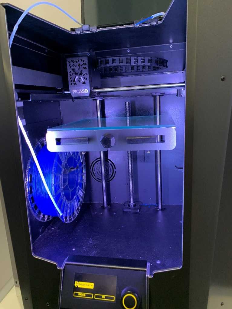
The last window displays the model of the 3D printer and the size of the currently installed nozzles, as well as the "availability" of the device.
The number of printers is not limited, you can connect at least 10, at least 20, at least 50 printers PICASO Designer X series. The main thing is that they be combined into one local area network. The program for managing printers Polygon X is installed on any computer within this network.
After connecting to the network, on the 3D printers themselves, it becomes possible to set the “availability” of a specific device to start 3D printing over the network. If "available for printing" is enabled via the printer interface, the operator can start a print job on this printer via the ethernet network. Please note that in this case, a USB flash drive (included in the kit) must be inserted into the printer. If this mode is not activated, you will be able to see the printer in the list of found devices, but you will not be able to press the "play" button to start 3D printing .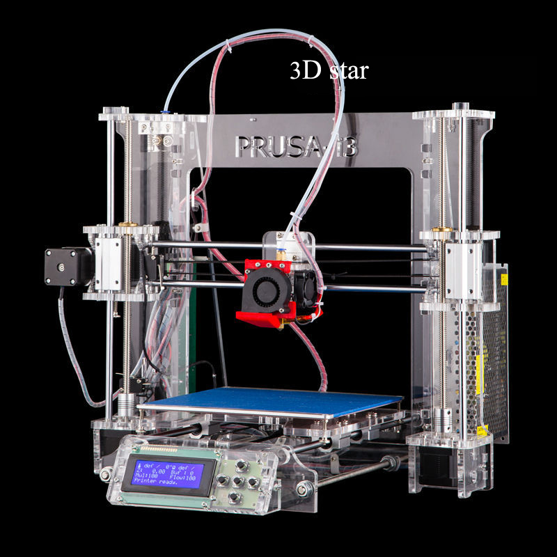
It should be noted that the meaning of the “availability” and “device unavailability” functions is to protect against incorrect actions of operators, especially when you have a large farm of PICASO 3D printers and 2 operators serve it. Those. after completing 3D printing , you need to go to the printer and perform all the procedures for preparing 3D printer for a new task ( remove the printed model, remove plastic residue, etc. ) and in the main menu after doing this, set the value " available for printing”, it is after this that operator Polygon X - will be able to start a new print on this printer. Thus, the system will not allow the printer to be broken by starting printing on a printer whose previous model has not been removed from the table.
When starting a print job locally from a 3D printer (without remote control), the availability of the printer does not need to be specified.
2.
 2 Setting up the network interface in the 3D printer.
Beyond Polygon X , work with a network connection in the printer itself has also changed a bit, firstly, in the interface of devices of the X line, the "Network Settings" menu has been added, in the "Settings" section of the main menu, and secondly, as we have already noted Previously, it was possible to mark a device as "available" or "not available" for remote control, depending on its status.
In "Network settings", it is possible to enable automatic mode for obtaining a network address from DHCP server. Or assign IP address and network settings manually. In this case, a single click on any of the items will allow you to set the corresponding numbers using the joystick, scrolling it to the right or left.
Also, the network name of the device and its current network parameters will be displayed here.
Let's move on to the innovations of the file system.
The second main innovation of this update was the new file system for 3D printer and for Polygon X .
Moreover, both on the printer itself and in the program interface, changes are available to the naked eye.
The first thing that catches your eye is the presence of a third, additional stage in the “line” of task preparation stages on the main screen (see below).
The “Network” circle appeared on it, which contains:
-
list of files prepared for sending (on the right side of the screen)
-
setting the display of file data (on the left side)
-
and the printer management tab.
In order to use this menu, first you need to add and calculate 3D model , after which a new button “add to database” will appear on the “task” tab
This database of tasks is a list of files registered in the program, which can either be sent for printing via the network interface, or organized from them into a “print list”, about them below.
By the way, it is not necessary to wait for a 100% download of a job when sending it to print remotely. You can start this process almost immediately, the file will be loaded in real time.
3.1 Print sheets
What is a Print List? The easiest way is to compare it with the playlist of any music player. You have a list of files that are played in a specific order and matched with a specific meaning.
For example, you have a product consisting of a large number of parts. Each detail has its own task. Suppose one of these tasks according to the assembly scheme must be repeated several times.
It is this task that the new function is designed to facilitate. The print list allows you to track the execution of the entire “product” and count how many times a particular file has been launched. Moreover, if the set number of files of a particular print list is completed, the smart program will prohibit the creation of extra copies.
The lists themselves can be saved for a specific 3D printer , or in the program interface Polygon X as a whole.
3.2 Updated Print Menu
If before that we were talking only about Polygon X , then you might get the impression that almost nothing has changed on the interface of 3D printer , this is not so. To match the new file system and support Printlists , the Print menu has been redesigned.
Now you can select specific files for printing, or use Print List . In this case, all the functionality of the latter will also be displayed on the display.
Also, an indicator of the printer's readiness for printing has been added to this menu, we talked about this earlier.
Among other things, the elapsed time counting system 3D printing has been redesigned. Now it is considered correctly and written off accordingly in the same way.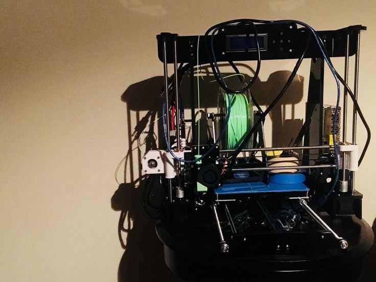 The starting point is the moment of switching on 3D Printer when the global timer starts.
Let's briefly go over the "small" fixes in general. Which typed, judging by the announcement - a lot. In fact, even more, but some very subtle things simply did not fall under the description.
4.1 Innovations Polygon X
As many of you probably noticed even from the screenshots, the interface of Polygon X has changed a bit. The Mission Calculation button has moved to its rightful historical place in the lower right corner of the screen. This is done as part of the interface philosophy - more space for the active viewing area and we have insider information that this is just the first small touch in a series of many changes that will transform Polygon X externally in the future.
In addition, the old task preparation modes were renamed, because users often confused them with the print speed mode names on the 3D printer. Now they do not duplicate each other and from the description it is more clear how exactly one mode differs from another (see below)
Yes, by the way, tooltips have also been redesigned. Added new and corrected old descriptions. Some were written from scratch. Job preparation just got easier!
Also in the interface of the slicer Polygon X the names of the type of global settings in which the program works have changed - now it is a basic and professional view. With the latter, as you might guess, an extended list of settings is available to you (see above).
From this version Polygon X the old file format .plg is no longer supported. This is due to a number of critical vulnerabilities due to the difference in formats.
4.2 3D printer interface.
The interface of the 3D printer has also received some important changes. To begin with, in the “Sleep” mode, only the illumination of the working area goes out. The display changes its brightness to dim, but is still visible. Practice has shown that this approach is more convenient to simply turn off any backlight.
Also, the system for registering and displaying errors has been redesigned. Now the printer writes not only the error code, but also how many times during the printing process it occurred, as well as its brief description.
Again, many old bugs related to menu scrolling and other nuances have been globally fixed. Their list is quite large, but they arose very rarely and do not require a detailed description.
5. Announcement of future updates.
In conclusion, I would like to say that this update is the first in a series of Important updates Polygon X in the future. Looking ahead, you can dream up and imagine that in the future Polygon X will acquire a new, more powerful mathematical engine, new settings functions will appear in it, and in general, the program will become more flexible and convenient.![]()
By the way, the .plgx format will become dominant and support for g-code will most likely (But this is not accurate! Note ed.) be excluded in the future. This is due to the file display format in the program and in the 3D printers themselves. Part of the functionality is already present in this version, for example, screenshots of the calculated task in the network mode.
One thing we know for sure - in the next version there will be even more new, useful and interesting, we are looking forward to announcements from PICASO3D !
I would also like to note that PICASO3D is the only manufacturer of 3D printers in Russia with its own slicer Polygon X . Which is constantly updated and available for download from the official website PICASO3D - for free.
Well, that's all we have! We hope this article was useful for you!
Order 3D printers PICASO Designer X Series you can in our company we since 2016 are the official distributors of the plant:
• By e-mail: Sales@3dtool. ru
ru
• By phone: 8(800)775-86-69
• Or on our website: http://3dtool.ru
Also, don't forget to subscribe to our YouTube channel:
Subscribe to our groups in social networks:
In contact with
We assemble a 3D printer with our own hands. Step-by-step instruction. Part 4.
Friends, hello!
At the end of today's part, our printer will be printing.
Let me remind you what we have already done:
1. Introductory. Purchasing everything you need. 2. Assembling the printer. Part one. Body and mechanics. 3. Assembling the printer. Part two. Electronics. 3.1. Additional photos. 3.2. Connecting the electronics 4. Firmware and printer setup - Marlin.
5. Firmware and printer setup - Repetier-Firmware.
Today we need a multimeter, a computer, the USB cable that came with the Arduino Mega, an SD memory card.
I warn you right away, before plugging this whole thing into a power outlet, check if everything is connected correctly 7 times, and when working with a multimeter, one awkward movement and Arduino to replace. I have already killed 3 Arduino Mega, including one when setting up this printer, and so that you do not have to wait another two weeks for this post, I quickly found a new 'dunya' on Avito. If in any doubt, double-check or ask again! If I warned.
First things to check:
1. Position of the drivers.
2. Correct connection of limit switches.
3. Polarity of all wires.
4. General wiring diagram for all electronics.
Have you checked? 7 times? Let's go further:
We plug our printer into the socket, turn on the switch (on the power cable connector with a fuse and do not forget to install the fuse), it should turn on:
1. The fan on the power supply.
2. RAMPS blower.
3. Print head heatsink airflow.
4. Screen backlight.
5. Printer backlight, can be turned on or off with the switch.
Working?
No - go to the previous chapters.
Yes - let's move on.
I took a picture from my neighbors:
Using a multimeter, we measure the voltage (DC Volts - V). By the way, just at that moment my hand trembled, and I first soldered the stabilizer, which is most often on fire in this situation, then I realized that not only the stabilizer had burned down, I went for the 'dunya'. On A49 drivers88 can be handled without a multimeter, just by the sound, but we follow the rules, set the voltage to 0.68V on all drivers, for A4988 you can up to 1V.
Ready?
Going further:
Downloading here - Arduino Software, lately strange things have been happening with this program, I have version 1.6.5, my colleagues have other versions. Install on your computer.
most likely we have a 'dunya' not a 'dunya' at all, but a Chinese clone on the Ch441 chip, then we also download the driver, for example here - install it on your computer.
Download the firmware - Marlin - unpack the archive with the firmware to a convenient place.
Downloading the library - u8glib - do not unpack the archive.
We connect the printer to the computer via a USB cable, the drivers are installed and as a result you should see the following picture in the device manager of your computer:
Remembers the number of the COM port on which your Arduino board is installed.
Open the file ...Marlin-RCMarlinMarlin.ino (in Windows Explorer it can be just Marlin without extension) using Arduino Software:
Next go: Tools - Board:... - Choose your board Arduino/Genuino Mega or Mega 2560.
Next: Tools - Processor:... - ATmega2560(Mega 2560).
Next: Tools - Port: ... - We select the same COM port that we remembered in the device manager of our computer.
Going further - open the Configuration.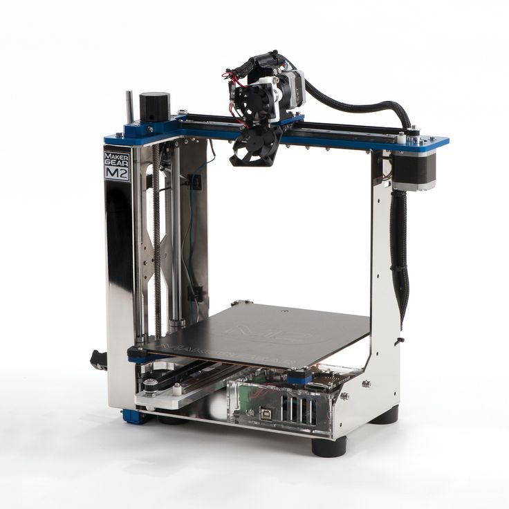 h tab:
All basic settings will be made in this tab.
We need to add a library to work with our screen - u8glib, we have already downloaded it, then we need to add it to our firmware.
Go Sketch - Include Library (Add Library) - Add .ZIP Library...
In the window that opens, look for your archive with the u8glib library, select it and click open.
Next Sketch - Include Library (Add library) - at the very bottom we see u8glib appeared, select it.
A line appeared in our sketch:
#include Starting the firmware configuration:
1. You need to select the controller of our printer, for this we go to the boards.h tab
We see there a huge list of controllers with which the Marlin firmware can already work:
Let me remind you that we use Arduino Mega 2560 + RAMPS v 1. 4 and we have a heating table, controlled blowing of the part and one print head. I think everyone has already found our board:
#define BOARD_RAMPS_14_EFB 43 // RAMPS 1.4 (Power outputs: Hotend, Fan, Bed)
Return to the Configuration.h tab line:
2. Setting the table temperature sensor.
Most likely you, just like I have a regular Chinese 100K thermistor, in this firmware it is denoted by the number 1:
// 1 is 100k thermistor - best choice for EPCOS 100k (4.7k pullup) hotend and for the table:
We can leave the maximum and minimum temperatures unchanged or adjust to our needs:
3. PID settings - I recommend doing it after you have already printed on your printer for several hours.
This is done as follows, in the Pronterface program, you need to connect to the printer
and give the command
Where M303 is the calibration command, E0 is the hot end, C10 is the number of heating-cooling cycles, S260 is the typical temperature of the nozzle.
The printer runs the hotend heating 10 times, after that it outputs the values Kp, Ki, Kd. We write these values into these firmware:
The same for the table, only the command:
M303 E-1 C10 S110
Where E-1 is the table, S110 is the typical table heating temperature.
Due to prolonged heating of the table, a timeout error may occur, just restart the command.
Enter the obtained values into the firmware:
4. Set up the operation of the limit switches:
Let me remind you that in our case we use:
Maximum for Y
Maximum for Z
//)/uncomment the corresponding lines:
And also change the direction of the location of the 'house' in accordance with the position of the trailers:
4. Print field size settings.
In my case it turned out to be exactly 200*200*190 mm:
Your values may differ slightly, literally mm, but this is established empirically later.
5. Setting the speed of moving home:
Established empirically, while leaving the default.
6. Setting the movement steps along the axes.
We need to find out how many steps our printer takes per unit of distance (in our case 1 mm) along each of the axes.
In our case, we use a motor that takes 200 steps per revolution, and we break this step into 16 microsteps.
Further along the X and Y axes we have a belt drive with a pitch of 2 mm for each tooth and a spool with 20 teeth.
Thus, our engine makes 200 * 16 = 3200 steps in one revolution and overcomes the distance 20 * 2 = 40 mm in these 3200 steps.
Therefore, in order for the printer to move 1 mm, it takes 3200/40 = 80 steps (this value is the same for the X axis and the Y axis).
A trapezoidal screw is installed on the Z-axis, which has a different pitch, who bought what. For example, 8 mm per full turn, i.e. our printer travels 8 mm in one turn of the screw along the Z axis and does the same 3,200 for this, although to accelerate the Z axis, you can set crushing (with jumpers) and 1/8, how to do this is written in 3 parts.
So along the Z axis, in order to move 1 mm, the printer needs to make 3200/8 = 400 steps.
Extruder feed. In order to understand how much our extruder feeds plastic, we need to calculate the circumference, from the school geometry course, remember that the circumference is 2 * 'number pi' * radius of the circle or 'number pi' * diameter of the circle. Now we don’t need special accuracy (we will adjust it more precisely later), the diameter is approximately 5.8 mm, therefore, in 3200 steps or one revolution, our extruder delivers 3.1415 * 5.8 = 18.2207 mm of the bar, and for the feed of one mm he needs 3,200 / 18.2207 = 175.624 steps, rounding up to the whole step 176.
We write the obtained values into the firmware:
Here, in order, X, Y, Z, extruder.
7. Setting speeds and accelerations:
leave these parameters unchanged for now and will adjust them in a more precise setting:
8. Screen settings:
Uncomment (remove double slash //) from the lines
#define ULTRA_LCD
#define DOGLCD
#define SDSUPPORT
#define ULTIPANEL
#define REPRAP_DISCOUNT_FULL_GRAPHIC_SMART_CONTROLLER
9. You can name your printer after yourself, for example 'Plastmaska'
To do this, uncomment the line:
//#define CUSTOM_MACHINE_NAME 'Plastmaska'
All basic firmware settings are done, check by pressing the 'Check' button :
And download by pressing the 'Load' button:
After that, our printer will reboot and show you various parameters.
Now we need to fine-tune the printer:
1. the correct direction of movement along the axes.
Should be:
X-axis - left 0 (or minus), right 200 (or plus)
Y-axis - towards you 0 (or minus), away from you 200 (or plus)
Z-axis - up 0 (or minus), down 190 (or plus)
extruder - feeds plastic is a plus, rolls plastic is a minus
If everything matches, move on, if not, then change the parameters, change the parameter true to false or false to true - parameter changes only where it is needed (where movement along the axis is wrong):
#define INVERT_X_DIR false
#define INVERT_Y_DIR true
#define INVERT_Z_DIR false
#define INVERT_E0_DIR false
compile and re-upload the firmware, check, match.
2. Limit switches operation:
Place the carriage and table in such a way that the limit switches are not pressed.
Command M119 via the Pronterface program.
We see something like this:
or so
should be correct:
or
x_min: open
y_max: open
z_max: open
This is only for normally closed contacts, if you use normally open, then you should have the opposite, the limit switch did not work - open, the limit switch worked - TRIGGERED.
If something is wrong here, then most likely they made a mistake in the previous setting of the limit switches or in their connection. go back and check.
3. Proper travel home.
We give a command to the printer to go home, it is possible through the printer menu, it is possible through programs on the computer.
The carriage should move to the left and away from you, the table should move down.
Is everything right? moving on. Not? we return to the firmware
4. We select the dimensions of the movement:
here everything is empirically and with a ruler we select the parameters for all axes and enter them into the firmware:
5. Checking the bar feed:
We take a line, measure 10-20-30 cm bar, mark and give the printer a command to squeeze out 10-20-30 cm of the bar, check how accurately he did it, based on the values we correct the firmware.
6. Selection of speeds and accelerations:
No one will tell you better than Sergey Taranenko:
We enter the obtained parameters into the firmware, fill it in the printer, check it.
7. Setting the gap between table and nozzle.
The table must first be coated for good adhesion to the table, I personally use a glue stick (3M Scotch, UHU, Kalyaka-Malyaka). I put glue on cold, clean, dry glass, after that you can heat the table, one of these days I plan to try glass-ceramic glass, nothing works from a pencil that has been tested better.
We heat the table and the nozzle to the operating temperature (110/250) send the table to point 0, then three points further (where we have the adjusting screws)
Adjust the distance with nuts so that a sheet of paper is pressed between the nozzle and the table nozzle to the table, but at the same time it could be pulled out without tearing, it is necessary to achieve this so that there is such a distance at any point of the printer, for this it is enough to align the table 2 times at 3 points.
Some of the parameters can be changed via EEPROM, this can be done either in the Repetier-Host 9 program0029
Or using commands in the same Pronterface.
That's probably all, I'm waiting for your questions, on the basis of which I want to make a certain FAQ on the printer.
Also the last chapter '5. Firmware and printer setup - Repetier-Firmware.' is postponed indefinitely, because the printer on which it was planned to install this firmware suddenly received MKS Sbase, and that's another story.
Finally, once again a video of how the printer prints:
and this is what happened:
Another well-known model, but of higher quality and better material:
Well, the new owners of the printer are happy.
Examined:
Adhesive coating applied:
We set to work:
What I plan to do next, the first thing is to complete the project with a double-headed printer:
But in the near future I want to make a plywood Ultimaker Go, I really liked the idea of wearing takeaway:
It is possible that Repetier-Firmware sells there too.