Artec group 3d scanner
Professional 3D Scanners | Artec 3D
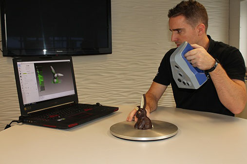
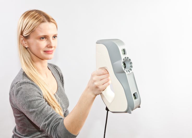
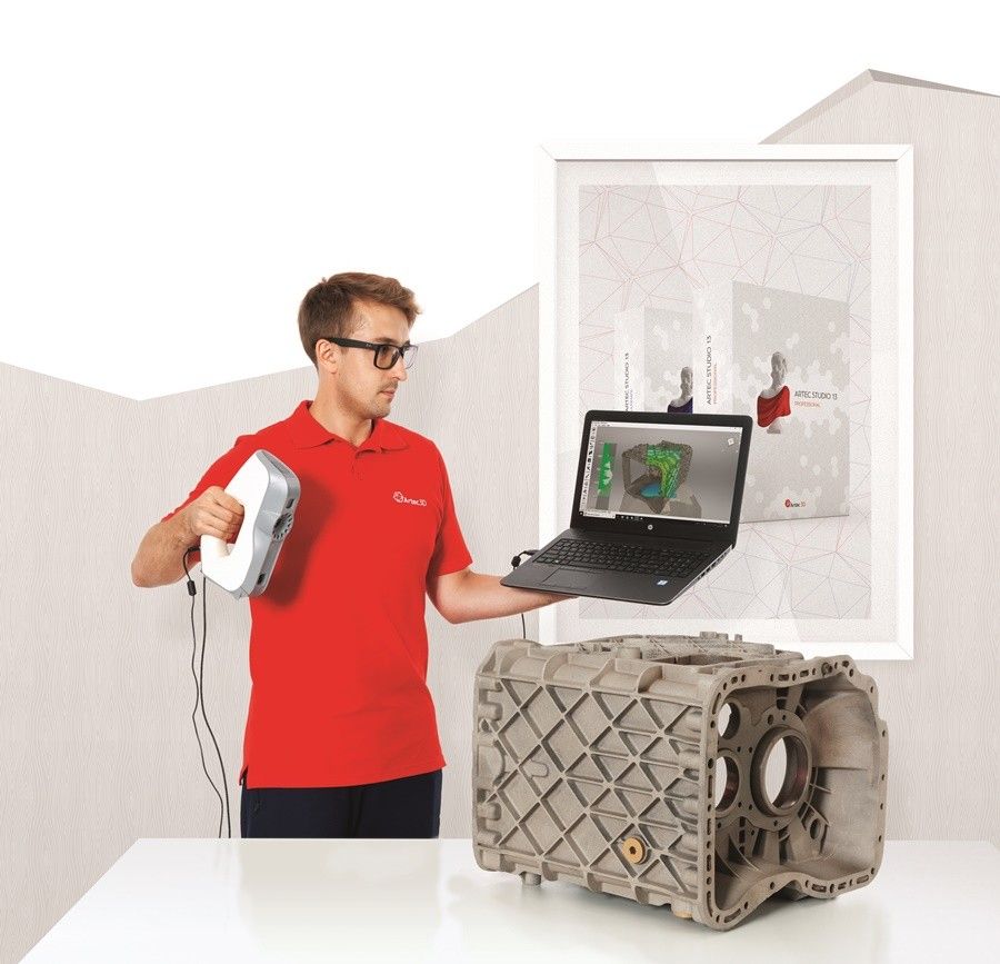
Handheld 3D scanners
Easily capture all angles of your object at speed
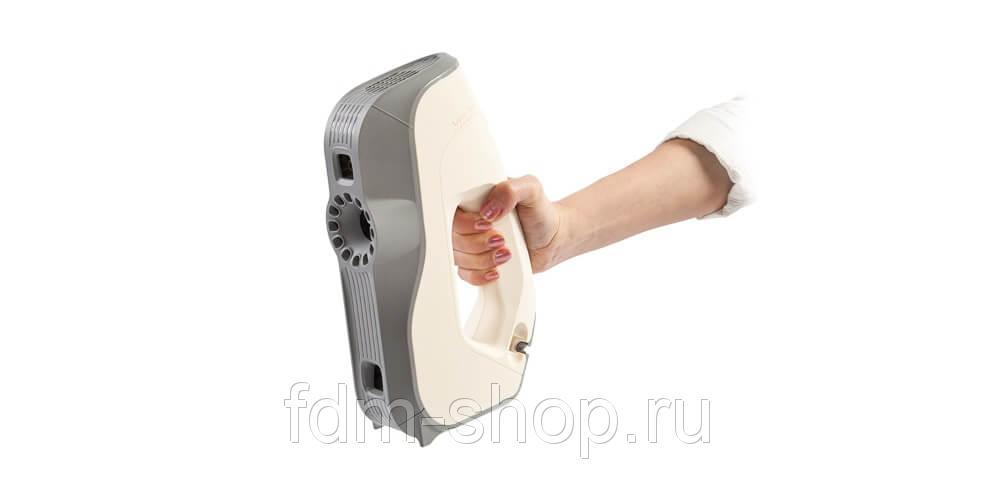
Leo
Our most comprehensive 3D scanner featuring wireless technology and an inbuilt touchscreen for instant data projection.
Space Spider
This new-generation metrological device is equipped with automatic temperature stabilization for high-precision scans.
Eva
Our most popular product, Eva is fast, versatile, and accurate.
Eva Lite
Entry-level structured light 3D scanner with geometry-only tracking and data capture.
Metrology-grade 3D scanning solutions
Capture both tiny and large objects or areas with the maximum precision. Ideal for quality assurance
Ray
Professional long-range laser 3D scanner with an inbuilt battery and sub-millimeter accuracy.
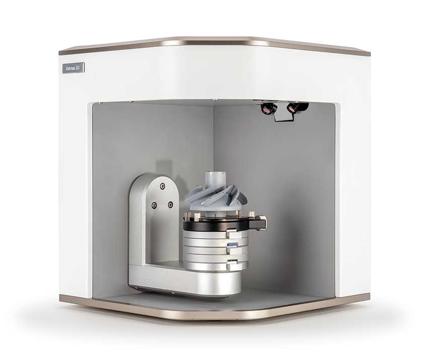
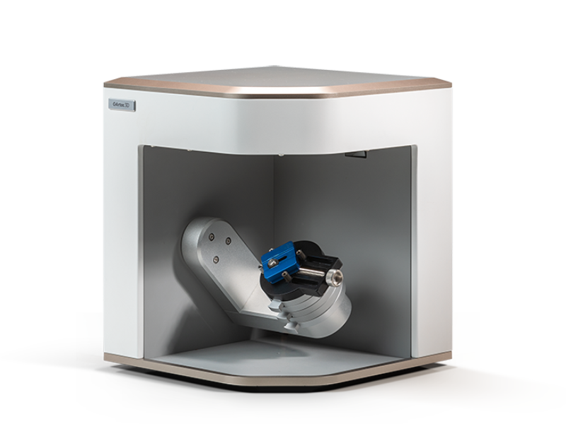
Micro
High-accuracy desktop 3D scanner for tiny parts, such as engine valves and connectors, jewelry, or dental components.
Artec Metrology Kit
A 2-micron measurement solution, ideal for inspection and reverse engineering.
Compare scanners
Find the 3D scanner best equipped for your industry or application.
How to 3D scan an object with a portable structured light scanner
When using a structured-light 3D scanner, there are certain rules and factors every professional should know.
How-Tos
Best 3D scanners — review by Artec 3D
After reviewing the top 3D scanner lists available on the Internet, we noticed that most don’t include information about the key parameters of the objects you need to scan. Important categories such as object size and the application(s) you’ll be using the scanner for are not covered.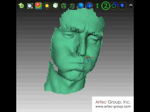 This review aims to fill this gap and help you find the best 3D solution for your project.
Reviews
How does 3D scanning technology work?
Starting out in the world of 3D scanning can be intimidating, but everything becomes clear once you take a moment to understand the technology behind it. From your own eyes (the original scanner!) to the latest 3D scanner on the market, here’s how it all works!
Explainers
What is laser 3D scanning?
In this guide, we take a deeper look into one of the most popular 3D scanning technologies – laser 3D scanning. After reading it, you’ll be familiar with what types of scanners are referred to as “laser,” how they work, where they’re most useful, and what they are used for.
Explainers
Selecting the right 3D scanners for successful 3D printing
When it comes to 3D printing, software is often just as important as hardware. Here’s a look at which 3D scanners work best for 3D printing, and how you can get started.
Guides
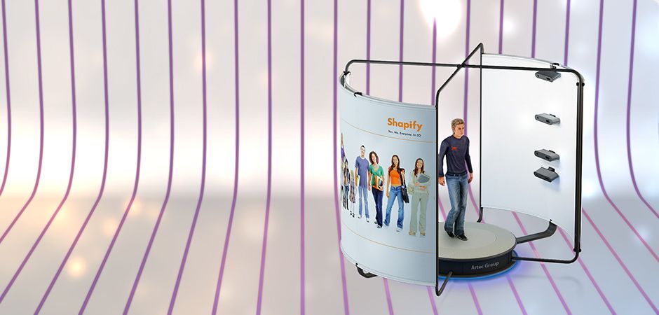
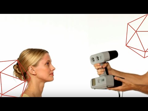
3D body scanning from A to Z
From custom prosthetics to perfectly fitted clothes, 3D printed figurines to realistic game avatars, 3D body scanners are becoming a key instrument for gaining valuable insight into the human body. In this article, we’ll cover the different types of body 3D scanners, the main challenges of capturing the human body, and look at how they are being used in medical, sports, clothing, and entertainment industries.
Guides
See all materials
Buy Handheld 3D Scanners and 3D Scanning Software at Best Price
Artec Leo Premium Pack
Ultimate 3D scanning pack that has everything you need: top-level handheld scanner, Calibration Kit, extended warranty, maintenance, software subscription, and then some.
Artec Leo
Our best 3D scanner, equipped with wireless technology and an inbuilt touch screen
Artec Eva
The ideal 3D scanning solution for making quick and accurate 3D models of medium-sized objects
Artec Space Spider
A metrological 3D solution, perfect for capturing small objects for CAD applications and more
Artec Eva Lite
Entry level white light 3D scanner.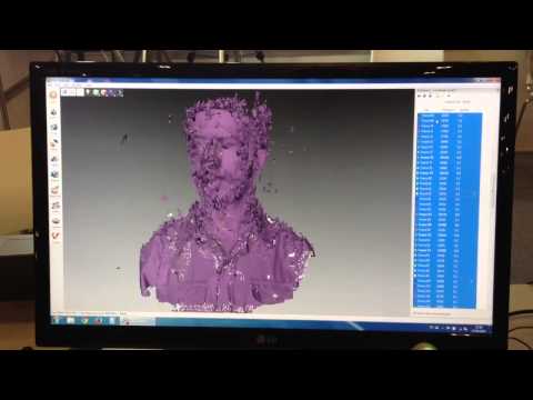 Geometry tracking and capture only.
Artec Ray
Long range laser scanner for digitizing large objects, such as airplanes or buildings.
Artec Micro
The perfect metrology-grade desktop 3D scanner for quality inspection, jewelry and dentistry.
Artec Metrology Kit: Entry
Optical coordinate measuring system for inspection and engineering. Accuracy up to 4 microns.
Artec Metrology Kit: Professional
Optical coordinate measuring system for inspection and engineering. Accuracy up to 4 microns.
Upgrade Eva Lite to Eva
Get the full power of Eva’s color tracking and capture features.
Leo + Space Spider
A combo of our powerful 3D scanners. Ideal detailed capture of multiple objects.
Space Spider + Eva
Duo of professional 3D tools available at a special discounted price
Special offers
Educational packages
Artec handheld 3D scanners available at lower prices for classroom use
View more info
Geomagic Design X bundle
An all-in-one reverse engineering solution with Artec Studio and 3D engineering software
View more info
Geomagic for SOLIDWORKS bundles
Export your 3D scans directly to SOLIDWORKS and make manufacture-ready 3D models
View more info
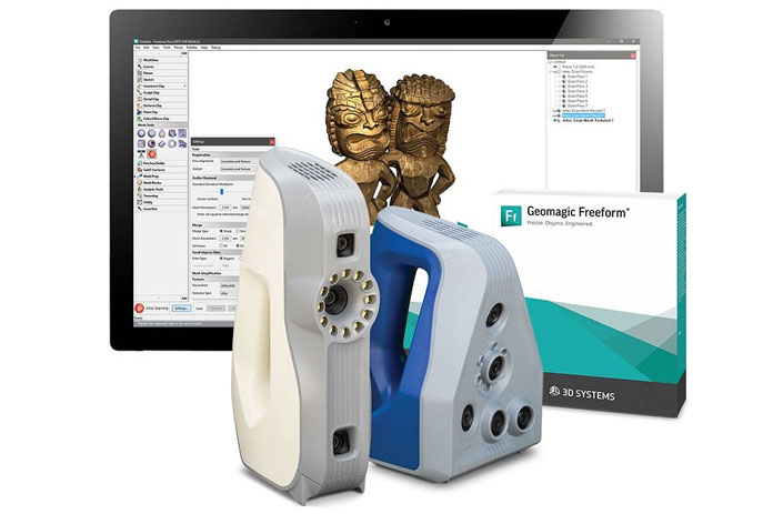
Geomagic Freeform bundles
A winning combination for hands-on organic product design and manufacturing
View more info
Geomagic Control X bundles
An outstanding combo for extensive quality control with easy data capture and analysis
View more info
Geomagic Wrap bundles
A great solution for comprehensive exact surfacing with an extensive toolbox
View more info
Artec software
Artec Studio 17 Trial
An easy way to get started.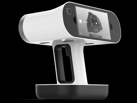 Try Artec Studio for 30 days at no cost.
See all plans
Free download
Artec Cloud
Annual, renewed automatically every year
See all plans
200 GB
12 months from date of payment
See all plans
12 months from date of payment
See all plans
Geomagic software
Geomagic for SOLIDWORKS
An ideal scan-to-CAD solution for a seamless workflow in SOLIDWORKS.
Geomagic Design X
Optimal reverse engineering software for fast conversion of 3D scan data into CAD models.
Geomagic Control X Professional
A powerful metrology solution with an advanced set of tools for a flexible workflow.
Geomagic Wrap
A versatile solution with an extensive toolbox, perfect for exact surfacing.
Optional equipment
Leo Calibration Kit
Pre-order yours today! Recalibrate your 2022 Artec Leo in your own time, and in your own environment, to ensure its accuracy always stays at its highest.
{{ getPrice() | formatPrice }}
Add to cartWhere to buy
Artec Turntable
A smart turntable for effortless 3D scanning of small objects with Artec Space Spider.
{{ getPrice() | formatPrice }}
Add to cartWhere to buy
Smart battery charger (Leo)
High-performance and intelligently designed to deliver maximum charges, while extending battery lifespan to the fullest.
{{ getPrice() | formatPrice }}
Add to cartWhere to buy
Eva/Spider battery pack
Scan anywhere for up to 6 hours non-stop. Includes a pouch, a charger, and a power cable for connecting the battery to the 3D scanner.
{{ getPrice() | formatPrice }}
Add to cartWhere to buy
Artec Eva hard case
Designed with Eva’s measurements in mind, this hard case will keep it safe during storage and transportation.
{{ getPrice() | formatPrice }}
Add to cartWhere to buy
Space Spider calibration kit
This kit is there to make sure the accuracy of your Space Spider remains at its highest at all times, even after a sudden jolt!
{{ getPrice() | formatPrice }}
Add to cartWhere to buy
Battery pack cable
Got a field scanning job lined up but your dog has chewed the cable of your Eva/Space Spider battery pack? Order a replacement in just a few clicks!
{{ getPrice() | formatPrice }}
Add to cartWhere to buy
Power supply for battery pack
No matter what extra accessory you may need, Artec 3D has you covered.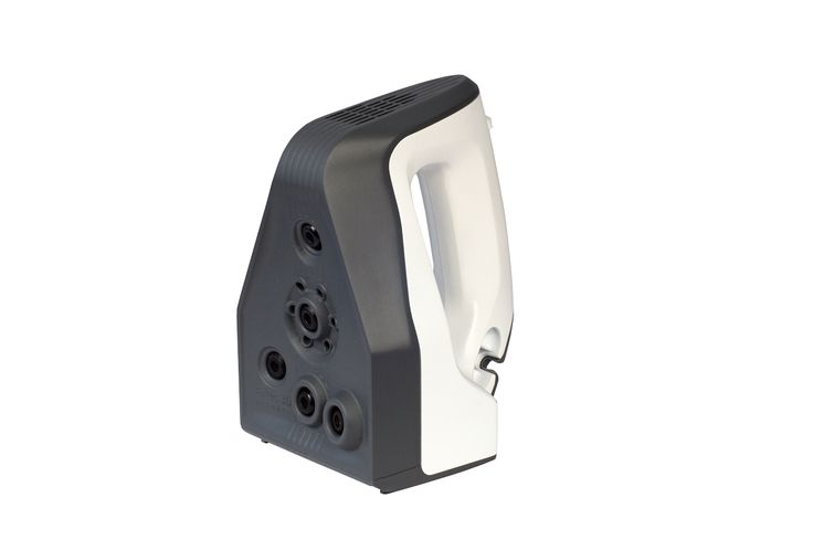 Order this native power supply unit to charge your Eva/Space Spider battery pack the fastest and safest way possible!
{{ getPrice() | formatPrice }}
Add to cartWhere to buy
Eva/Spider USB cable
A fully tested cable featuring the connector needed for your Artec scanner.
{{ getPrice() | formatPrice }}
Add to cartWhere to buy
Eva/Spider power supply
1.8 m power supply developed exclusively for Artec 3D scanners for stable performance
{{ getPrice() | formatPrice }}
Add to cartWhere to buy
Artec USB Kit
Maximize your Artec Eva or Space Spider’s FPS rate with a USB 3.1 to Thunderbolt 3 adapter and add a 5 m extension to your scanner’s USB cord for scanning over longer distances.
{{ getPrice() | formatPrice }}
Add to cartWhere to buy
Scanning — Artec Studio Documentation 12
Scanner buttons and capture modes
The 3D scanner can be in one of the following capture modes (each mode has a specific color and flashing frequency of the LED on the device case if an Artec scanner is used):
Rice. 43 Shooting mode diagram (colors match scanner LED)
- Inactive - Solid green LED
-
This mode indicates that the scanner is recognized by the application or that the Stop button on the Capture panel or the button on the scanner body is pressed (see Fig. 12). In this mode, the flash of the 3D scanner does not blink.
- Preview - LED flashes red.
-
In this mode, the 3D scanner captures images, but the application neither registers nor records captured frames. To start this process, click either the Preview button on panel Shooting (see Fig. 55), either the button on the scanner body, or the key
F7on the computer keyboard. This mode is useful in the following cases:-
Checking the field of view of the 3D scanner
-
Finding the best position for an object
-
Preparing for recording and working through the scan procedure
-
Texture brightness adjustment
-
- Entry - constant red LED indicator
-
This mode scans and writes data to the computer's RAM or disk.
 The mode can be activated by pressing the Record button on the panel Survey , or the
 Space keyon the keyboard, or the button (first press for Preview , second for Record ). To pause recording, press either the Pause button on the Survey panel, or the button on the scanner body, or the 9 key0027 Space on the keyboard.
Selecting and preparing objects for scanning
Artec 3D scanners use the structured illumination method for 3D reconstruction. Because 3D images are captured using optical technology, some types of objects may be difficult to scan. However, certain techniques allow you to successfully scan such objects. For example, you can apply a thin layer of paint or talcum powder to transparent or dark objects. You can also use other easily removable materials or a special anti-reflective spray.
| Surface characteristics | Possible solutions |
|---|---|
| Black or very dark | Apply anti-reflective spray |
| Shiny and reflective objects | Apply anti-reflective spray, tilt scanner when shooting |
| Clear (glass, certain plastics, etc. | Apply anti-reflective spray |
| Fine edges | Add background geometry (e.g. wrinkled paper) |
Scanning techniques
Artec 3D scanners capture objects at up to 15 frames per second to ensure that adjacent areas of the frame overlap with smooth scanner movement. Artec Studio uses features in overlapping areas to automatically align captured frames. It performs this task in real time, providing the user with immediate access to frames in a single coordinate system. This makes it possible to evaluate the scanned area after the end of the session and determine which parts of the object need additional scanning.
Fig. 44 Scanner orientation and repaired surfaces
fig. 45 Rangefinder in window 3D view showing surfaces within the optimal range of the Artec EVA
scannerTo capture an object or scene accurately, follow these steps:
-
Pay more attention to the object on the screen than to the actual object.
-
Verify that Artec Studio can accurately align frames from the scanner. To do this, follow these steps:
-
Do not move the scanner too fast
-
Hold the object as close to the center of the field of view as possible
-
Keep the scanner oriented so that surfaces fill the field of view sufficiently (Fig. 44)
-
Try to position the scanner as close as possible to the center of the rangefinder [1] or slightly below it (closer to the object) (see Fig. 45)
-
-
If you are scanning an object in several scans, then in order to successfully combine them, do not forget to capture a common area in each of them.
-
If you are scanning an object in one scan, capture the object from all sides regardless of direction, plus a little more (360+ degrees)
-
Avoid scanning objects that may change shape during the shooting process.
 In conditions where the scene changes, the system may not determine the correct position of new frames relative to those already aligned. If foreign objects get into the frame, then you must remove them later at the editing stage (see Editing scans).
 -
Do not record too many frames: make sure that all areas are sufficiently scanned, but do not shoot them twice, except when recording areas of overlap for successful registration.
| [1] | From a technical point of view, the center of the rangefinder is the center of the depth of view. The 3D scanner has near and far clipping planes (Fig. 11), which determine the optimal distance between the device and the object being scanned. For a visual visualization of the distance to the scanned object, Artec Studio implements tool Range finder , which is a set of translucent histograms located on the left in window 3D view (see Fig. |
 45). Each histogram displays the distribution of points of the obtained surfaces by the distance to the scanner. The color of the histogram corresponds to the set of surfaces from which it is derived: by default, gray is used for registered keyframes, light green for the last few frames of the registered sequence, dark green for the last successfully registered frame, and red indicates registration failure.
 Scanning procedure
-
Prepare the object and make sure it has enough geometric and textural detail (see Selecting and preparing objects for scanning).
-
Create even lighting without direct sunlight.
-
If only one scanner is connected to the computer, Artec Studio will automatically select it; otherwise, you will need to select the desired instrument from the list in section Optional panels Survey .
-
Before starting work, create a new project: use the button on the toolbar Workspace , or select the menu command File ‣ New Project, or use the keyboard shortcut
Ctrl + N.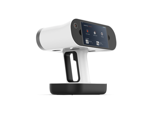 Once you have saved a project, you can load and unload scans as needed, thus controlling the use of RAM (see Working with projects for more details).
 -
Decide on the number of sessions needed to capture the entire subject. By using a special turntable (3rd party), you may be able to eliminate the need to turn the object by hand. Depending on your choice, you can:
-
Rotate the object itself
-
Locate so that you have access to all areas
-
Use rotary table
-
-
Press Preview or on the scanner. Point the scanner at the object, practice moving around the object, taking into account Scanning Techniques.
Note
If you want to use the Enable Automatic Removal of Support option, first point the scanner at the surface supporting the object.
-
Press Record to start recording.
-
Move the scanner smoothly while observing the process in window 3D view
-
Shoot as much as you can and pause or end the recording by pressing the Pause or Stop buttons, respectively.
 Select Stop if you need to correct the object's position (see next step).
 -
Rotate the object or otherwise prepare it if necessary, and then scan the remaining areas.
-
Once you have successfully captured the object from all sides, press the Stop button or on the scanner body.
Positioning modes
The program offers three positioning modes (trajectory tracking) and one option:
- Geometry + Texture, or hybrid
-
The most optimal (and standard) algorithm for 3D scanners with a texture camera. Along with the geometric information of the object, the algorithm uses texture details from images taken from the texture camera. Due to this, when using this mode, the most likely successful scanning of flat or textureless objects. The only possible drawback of the algorithm is that it consumes more CPU resources than other algorithms, and therefore the scanning speed may drop on insufficiently powerful computers.
 You can use this mode with Artec MHT, Artec EVA, Artec Spider and third-party 3D sensors.
Fig. 46 Texture positioning method draws a colored object (current field of view circled in green)
- Geometry
-
Standard mode for all 3D scanners that do not have a texture camera (Artec EVA Lite). The positioning method uses the object's geometry to align captured frames, making it suitable for objects with rich geometry and useless for objects with large flat, spherical, or cylindrical parts. Positioning Algorithm Geometry uses the least amount of CPU resources compared to other algorithms.
Fig. 47 Main window during survey using Geometry positioning method
- Marks
-
Special algorithm for scanning objects with special marks pasted on their surface.
- Real-time fusion (option)
-
Also available for Artec 3D scanners and third-party 3D sensors, this option “glues” the results immediately after scanning.
See also
Adjusting scan parameters
Removing a support or reference surface
Often when you capture an object, you can exclude its reference surface from the scan. Option Remove support serves this purpose. To apply this option, first specify the surface on which the object is located, and then scan the object itself. If this scenario is not suitable for you, uncheck the Enable automatic support deletion box.
-
Open panel Survey .
-
Verify that the Enable Automatic Support Deletion check box is selected.
-
Click Preview and aim the scanner at a surface that supports the object (eg table or floor). A gray wireframe plane appears, representing the support.
-
Once the application detects the support, the message "Now scan the object" will appear.
Important
Even if Artec Studio fails to determine the reference surface, you can still start recording.

-
Point the scanner at the object and press the Record button ()
-
Scan the object freely. You can pause and resume your session as needed.
-
Press the Stop button, all scans will move to the coordinate system with the Z axis normal to the support.
-
Close panel Shooting . After Artec Studio performs Fine registration , algorithm Delete support will remove the previously detected support surface. If not, then delete it manually.
Fig. 48 Scanning with option Enable automatic support removal
Resume scanning after path tracking is interrupted
Artec Studio records adjacent frames based on feature data on a common surface. If the scanner stops recognizing common features, it will stop recording. This situation is called path tracking abort. If this happens, simply aim the scanner at the newly scanned area. It is worth noting that there are nuances here, which we will consider below.
Table 2 lists several reasons for broken track tracking. The most common cause is moving the scanner too fast.
| Cause | Possible solutions |
|---|---|
| Scanner too fast | Move scanner slower or increase Scan speed |
| Scanner sees too few surfaces | Apply anti-reflective spray or aim scanner at most of object; increase Sensitivity Artec Spider |
| Object does not have enough signature features to successfully track trajectories | Apply masking tape or draw markers on surrounding surfaces and/or move the scanner more slowly. |
Fig. 49 Warning: Trajectory tracking aborted
Option Scanning using autobuild can make it easier to resume tracking paths (this option is enabled by default in the application settings). Note the following:
-
Artec Studio almost immediately switches from Trajectory Tracking Aborted (see Figure 49) to Searching for position , which appears on a green background.
-
To continue scanning, point the scanner at the area already scanned.
-
Try to keep the original orientation of the scanner towards this area
-
This does not have to be the most recent scan, but it must have enough texture elements.
-
-
If the application successfully restores trace tracking, recording will start in a new scan. This new scan will already be aligned with the previous one.
The section Scanning using autobuild describes the behavior of the system when the option is disabled.
Align new scans with those marked in the Workspace
Automerge can speed up or simplify further processing. But if you have a project with position scans Geometry + Texture and the real scene has not changed, you can continue scanning immediately:
-
Make sure option Scanning using auto build is enabled (On) in Settings (see Capture).
:quality(80)/images.vogel.de/vogelonline/bdb/991500/991549/original.jpg)
-
Mark previously captured scans on the panel with an icon Workspace
-
Select Geometry + Texture and check the Align new scans with those marked in the Work area on the Survey panel .
-
Click Preview, point the scanner at the already scanned area with the texture, while maintaining the original orientation of the device, then click the Record button.
-
If trajectory tracking resumes successfully, Artec Studio will align the new scan with the selected ones.
Scanning with real-time fusion
Real-time fusion is a special mode in which Artec Studio builds a 3D model directly during scanning. This is the easiest and fastest way to get a model, however, it cannot completely replace the usual workflow for processing raw scans after they have been captured. Therefore, it is not recommended to use Real-time fusion in the following cases:
-
Scanning scene is large and video memory is limited
-
Complex shapes that cannot be scanned in one session
-
The object has small geometric elements
-
High precision required
Real time fusion is available for all positioning methods.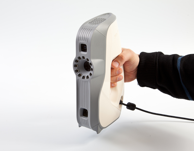
-
Open panel Survey .
-
Select the desired positioning method.
-
Check the Real-time fusion [2] checkbox.
-
Click Preview and then Record. Follow the recommendations in the Scanning Procedure section.
-
Pause and resume the session as needed.
-
When you have finished scanning, on panel Workspace one or more raw scans appear
Eva Scan1,Eva Scan2,Eva Scan3, etc., and one model named ``Eva Scan1-Fusion``. The number of raw scans corresponds to the number of times you paused and resumed scanning (see Figure 50).
Fig. 50 Panel Workspace after using Real-time Fusion
You can open the window Settings and in section Resources configure the following parameters Real-time fusion (see Real-time fusion settings):
- Voxel size
-
The 3D resolution of the model (in other words, the step size of the triangulation mesh in millimeters.
 ) The smaller the value, the more geometric detail you can see and capture in 3D.
| [2] | If you have selected Marks mode and cleared the Disable hybrid positioning method for .obc checkbox in the settings (see the Photogrammetry settings section), Artec Studio will also clear the Real-time fusion checkbox, because this combination of options is not supported. |
Scanning with marks
In general, no special equipment is required for imaging with the Artec scanner. If the object has hard-to-scan areas, the use of labels (tags) can be useful. In some cases, they can improve the trajectory tracking process and subsequent registration.
Placing labels
Regardless of the method you choose, you must place at least uncoded labels on the object.
Stick uncoded marks (Fig. 51) on the object following the rules:
-
Try to place them on flat areas
-
Avoid uneven surfaces
-
Do not cover important geometric elements with markers
Fig. 51 Uncoded marks on object
Note
The size of marks in is set in the Artec Studio Settings, as described in the Photogrammetry Settings paragraph. If you are using non-coded markers from the Scan Reference set, specify 5 mm for the inner diameter and 10 mm for the outer diameter. Marks of other manufacturers should be measured and the measured values of the outer and inner diameters should be entered in the corresponding fields of the settings dialog.
Place code marks if photogrammetry is selected (Using a Photogrammetry Kit (Scan Reference)).
-
Prepare the subject and the surrounding scene. All objects must remain still during measurement and scanning.
-
Place the cross (Fig. 53) on the stage, make sure it is fixed and clearly visible from all angles. Also check that all marks on it are clearly visible.
-
Place coded labels on the object and on the stage.
 It is important to distribute them in such an order that at least six to eight marks are visible in each photo frame. Scattered placement is preferable, and avoid symmetry and alignment in a straight line.
Fig. 52 Coded tags
Using only Artec 3D scanners
You do not need to have a photogrammetry kit to benefit from the tags placed on the scanned object. Artec 3D scanners can do all the work. This mode uses an extra-hybrid (Geometry + Texture + Labels) positioning method and does not require downloading file OBC .
-
Open the Survey panel in Artec Studio. Select Tags under heading Positioning method .
-
Scan the object from all sides
-
Start Global Registration
Note
Since you are scanning without loading the OBC file, the application itself registers the coordinates of the marks. You can then save the OBC file and use it for subsequent scan sessions. It is highly recommended to run Global Registration first.
Using the Photogrammetry Kit (Scan Reference)
The combination of dedicated position marks (labels) and photogrammetric measurement results allows you to scan large areas in one go, increase surface accuracy and increase productivity by reducing post-processing time. The only drawback of this method is the need for preliminary preparation. But after scanning, you will not need to collect scanned surfaces, and you can immediately go to Gluing (See processing in Brief about 3D scanning).
This synergy is achieved through the use of an Artec 3D scanner and photogrammetry solutions. There are several third-party photogrammetry solutions on the market. One such solution is Scan Reference . Set Scan Reference includes software and hardware (see Fig. 53): a digital camera, a reference scale cross, non-coded adhesive-based marks (used by Artec Studio to match scanned data with photogrammetric measurements) and reusable magnetic coded marks ( required for automatic photogrammetric measurements in program Scan Reference ).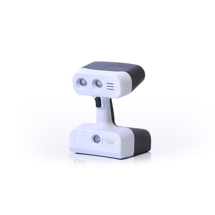
Fig. 53 Set Scan Reference
Set includes (from left to right): coded marks (foreground), digital camera, reference scale cross, tape spool with uncoded marks, transport case
To scan using marks, follow the instructions below:
-
Take several photos of the subject from different angles. Recommendations for camera setup, angle selection, number of shots and marks per frame can be found in the user manual Scan Reference and the FAQ article. General recommendations are as follows:
Take photos from 0.5 to 1.5 meters away with the flash on
Each photograph must include as many tags as possible and each tag must appear on at least ten photographs
The entire cross must be in the first 10-12 photographs
Capture an object from all angles
-
Remove the cross and code marks from the stage.
-
Connect the camera to a computer, copy the photographs and process them with the Scan Reference software. As soon as the calculations are completed, the results of the photogrammetric measurements of the object will be displayed on the screen. The results can be presented in the form of a table or a spatial model.
-
Save point model to
*.obcfile. This format is standard for the program. -
Open the Survey panel in Artec Studio. Select Tags under heading Positioning method .
-
Click the Load labels from file button and specify the path to the
OBCfile. -
Scan the object. When you're done, the program will collect all the scans.
Important
If you do not want textural and geometric features to make it easier to scan by marks, select the Disable hybrid positioning method for .obc check box (Photogrammetry Settings).
Using certain types of scanners
Features of scanning with Spider
Since Artec Spider has a smaller field of view compared to Artec EVA and provides higher accuracy, scanning with it can be difficult. Follow the recommendations in the Scanning Techniques section and the tips below:
-
Use a turntable whenever possible
-
Use a piece of paper with text as an artificial texture
-
Double check that the objects have not changed their shape and position
-
In some cases, try adjusting the sensitivity (see Sensitivity). Avoid extreme values.
The Artec Spider scanner is recommended to be used after it has reached its operating temperature. Immediately after connecting to a computer or power outlet, the scanner starts to heat up. When you open the panel General Survey , it displays, among other information, data on the current and optimum temperatures of the device. Warm up is faster when Artec Spider is in mode Preview . In this case, panel Survey also displays the estimated time remaining until the scanner reaches the optimum temperature.
Note
It should be noted that Artec Spider can be used at sub-optimal temperatures, but the accuracy of the resulting surfaces may be lower in this case.
Features of scanning with third-party 3D sensors
Important
Third-party 3D sensors are only available in Artec Studio Ultimate edition!
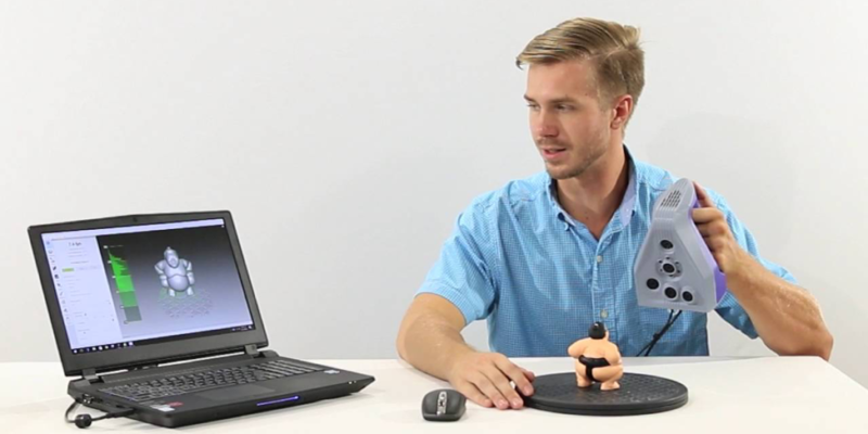
Third-party 3D sensors (see Device appearance) are not designed to perform 3D scanning. Being universal devices manufactured using cheap components, they allow you to scan objects, but the quality of the captured surfaces and textures is much worse than in the case of using professional Artec 3D scanners (see Fig. 54). Working ranges and fields of view of all supported in Artec Studio Ultimate 3D sensors are shown in Fig. 19.
Please note the following when scanning with third-party 3D sensors:
- Good lighting is essential
-
because none of the 3D sensors has a built-in flash.
 In addition, the use of these devices excludes the possibility of adjusting the brightness of the captured texture. This is why good lighting is so critical to getting an acceptable quality model. Do not over-illuminate the object, use directional light sources and fluorescent lamps. The Intel RealSense R200 is particularly sensitive to direct sunlight.
- When used with PrimeSense and Asus Xtion sensors
-
Use a special technique to help you capture surfaces with uniform brightness:
-
Click Preview
-
Point the sensor at the subject and hold it for about five seconds while it adjusts the white balance and exposure
-
Press Write button
-
Move the scanner smoothly to capture scene
-
Keep the sensor as close to the object as possible during scanning
-
- Most third-party devices work in real-time Merge mode
-
except Kinect ver.
 2 . Moreover, this mode is standard for Intel RealSense 3D sensors.
Fig. 54 Filmed and processed object
(scan of Artec EVA on the left and PrimeSense on the right)
MHT scanning features
The flash lamp in the Artec MHT scanner has a very high but still limited number of cycles, so always be sure to turn off the scanner when not in use. Do not leave the scanner on at the maximum (15 frames per second) frame rate for a long time. Artec Studio will automatically turn off the Artec MHT scanner after five minutes of continuous operation. The optimal operating/idle time for the scanner is 3/7 minutes, i.e. 3 minutes of scanning and 7 minutes of inactivity. This will significantly increase the life cycle of the flash.
Scan settings
55 Artec Studio Capture panel
Adjust texture brightness
Note
This option is only available for Artec 3D scanners with a built-in texture camera.
Texture brightness can be adjusted in mode Preview . By moving the slider, you can increase or decrease the brightness of the frames captured by the color camera (see Fig. 56). Note that texture brightness affects texture quality as well as track tracking stability. Also follow the recommendations in Table 3.
| Surface color | Recommendation |
|---|---|
| Dark or black | Brighten up |
| White or light colors | Reduce brightness |
Fig. 56 Brightness setting for color camera
Brightness decreased on the left and increased on the right (slider of the panel Survey is shown at the top for convenience)
Sensitivity
You can adjust the Sensitivity of the Artec Spider scanner if the application fails to restore certain surfaces. Increasing the sensitivity will make it easier for the scanner to capture black, reflective, translucent, and thin objects (such as human hair). The higher the sensitivity, the noisier the recorded surfaces will be. High values may also slow down the scanning speed. For Eva and other Artec scanners, this option is configured automatically.
Texture frame rate
Set the texture frame rate using the corresponding slider in the Settings dialog (see Texture recording mode and Fig. 152).
Turn off the scanner's flash
If you are unable to use the scanner's flash due to circumstances, follow these steps.
Fig. 57 Influence of ambient light on shooting results
Left: flash off, ambient light rather weak; the result is a dark texture. Right: flash off, ambient light improved; the result is a good texture.
Note that turning off the flash must be compensated by sufficient ambient light. According to our data, with the flash turned off, a texture of acceptable quality can be obtained if the illumination of the scanned surface is at least 1000 lux.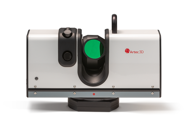 Compare models (Fig. 57) taken under different lighting conditions.
To get a textured model without using the scanner flash, follow these steps:
-
Open panel Survey , click on the link Advanced
-
Turn off texture flash by checking the Turn off flash check box
-
Create good outdoor lighting. Do not use fluorescent lamps.
-
Press Preview and point the scanner at the object
-
Adjust the Texture Brightness and Exposure Time for the texture. In most cases, values should be chosen as low as possible, since increasing the brightness can cause texture noise, and increasing the exposure time can cause blurring (loss of clarity). Instead of adjusting the sliders, try to improve the lighting even further.
-
Shoot a scene
-
To obtain a textured model, perform the required processing as described in Data Processing
-
Adjust the texture settings for the resulting model as described in Adjusting Texture.
 Pay special attention to the Hue and Saturation sliders. By moving the Hue slider, you can correct unwanted texture colors.
Exposure time setting
You can adjust the exposure time for the texture in mode Preview . Adjust this setting along with Texture Brightness. Increasing the exposure time can cause blurring of the texture. Do not change the default value unnecessarily.
Disable texture recording
Clear the Do not capture texture check box if you do not want to store texture information in your scans. It is located on the panel in section Advanced and turns off both the texture camera and the scanner flash. Note that this option is not available for the Artec EVA Lite scanner. Don't forget to check the box when finished shooting without texture. Otherwise, the next time you want to start normal shooting, the hybrid positioning method may not be available.
Important
Simply using the positioning method Geometry is not enough to stop the application from writing the texture. Make sure you uncheck the box of the same name.
Decrease scan speed
Artec EVA captures objects at up to 15 frames per second, while Artec Spider at up to 7.5. The default values guarantee comfortable scanning with smooth movements. However, if this speed is not to your liking, you can reduce it. In this case, Artec Studio will record fewer identical frames and register them faster. To do this, use the slider Scan speed on panel Survey .
Important
Reducing the scan speed can make shooting difficult. Use the slider only when absolutely necessary.
Additional settings
- Set your own scan name and initial scan number
-
by entering your own values in the fields Scan name and Start from , as well as changing the state of the smth checkbox. These values form the name of the scan on panel Working area (see Fig. 80, left). So, the default values "Eva Scan" and the number "1" can be changed, for example, to "Snapshot" and "14".
- Set up scanned data backup to disk
-
Enable shooting mode with simultaneous writing of scanned data to disk by checking the Save a copy of the scan to disk checkbox. The option is available only if you are working with an already saved project (see Saving a project) and can be useful when capturing a large amount of data on a workstation with insufficient RAM.
- Specify the delay (in seconds) before recording
-
using the Delay before recording start field in section Advanced of panel Survey . Then, after pressing the Record button, the application will delay the immediate start of recording for a specified number of seconds. To remove the delay, set the value to zero.
- Reduce the setpoints Working area limits
-
with sliders Middle (mm) and Far (mm) on panel Survey in section Optional . There you can only reduce the range within the given bounds.

- Set the working area limits (in millimeters)
-
By default, Artec Studio knows the values of the minimum and maximum limits of the working distance range for the device, within which clipping planes should be located. These values are tied to the type of connected device and provide good quality of the scanned 3D data. However, the operating range limits of Artec L scanners and 3D sensors can be overridden if scanning accuracy is of secondary importance. To do this, in the settings dialog on page Survey set the Redefine depth range checkbox, and then enter new boundaries of the scanning range (more about survey settings in the Survey section).
Warning
Non-standard values for the scanner operating range can result in loss of accuracy.
- Set panel hide Capture during scan
-
To enlarge the viewing window during scanning, the program automatically closes panel Survey as soon as you start recording using the Artec EVA or Artec Spider scanner.
 The Hide this panel during scanning check box is located in section Advanced and is unchecked by default.
Troubleshooting
| Problem | Possible solution |
|---|---|
| Geometry + Texture switch not available on panel Shooting . | Most likely you scanned without a texture. Uncheck Do not strip texture under Optional . |
| Noisy areas are visible in the resulting model. | You probably did not scan the damaged areas properly, or the scanner was too far from the object. Rescan them. |
| Error Trajectory tracking aborted repeats | Make sure Scan using auto-build is enabled (On) in Application Settings and use the positioning method Geometry + Texture . |
Artec S™ 3D Scanner in Moscow (Scanners)
- Russia
- Moscow
- Computer scanners
- Scanners Artec S™ 3D Scanner in Moscow
Price: Specify the price
for 1 unit.
- Minimum order - 1 unit;
- Offer added on 06/16/2017;
- Unique identifier - 18421399;
- The offer was viewed - 49;
Choose where it is more profitable to order a service or buy a product? “Artec S™ 3D Scanner”, check the price. The offer is currently available.
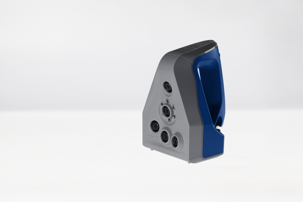
Product description
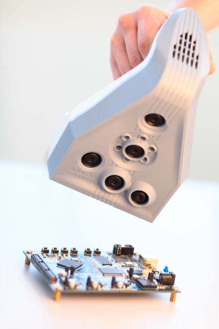
The Artec S™ 3D scanner is used for a variety of purposes, from scanning small, complex marble ornaments to digitizing toy shapes for production. The shape and size of the scanner resembles a conventional video camera. It is often paired with the Artec MH™ or Artec L™ models. This allows you to scan large objects with high detail of individual parts of the object.
General technical conditions
hardware characteristics
The ability to capture texture
no
3D resolution, up to
0.2 mm
0.05 mm
Up to
0.15% for 100 cm
Net
Color
no
Light source
flash lamp (not laser)
Working distance
0.15 - 0.25 m
Close range linear field of view, HxW
80 x 56 mm
Long distance linear field of view, HxW
134 x 93 mm
Angular field of view, HxW
30 x 21°
Video frame rate, up to
15 fps
Exposure time
0. 0002 s
Acquisition rate, up to
'000 dots/s
Dimensions, HxDxW
125 x 195 x 80 mm
Weight
1.6 kg
Power consumption
12 V, 36 W
Interface
1x USB2.0
No calibration required
Software specifications 0011
Parallel processing
Yes
Output format
OBJ, STL, WRML, ASCII, AOP, CSV, PLY
Performance
40'000'000 polygons per 1GB RAM
Supported OS
Windows Vista x64. Windows 7 x64
Minimum computer requirements
Intel Core Quad (I5 or I7 recommended), 8Gb RAM, NVIDIA GeForce 9000
Stereo support requirements
NVIDIA Quadro or better
Features Artec S™ 3D Scanner
- — Brand: Artec
Items similar to Artec S™ 3D Scanner
Please note that the BizOrg.