Arduino 2560 3d printer
How to Make a 3D Printer with Arduino – ELEGOO Official
Source: https://unsplash.com/
3D printing technology is wide, despite having been around for a little over 30 years. The improvements the technology has been undergoing are all slowly pushing it slowly towards a realm where everyone will be able to access simple 3D printers at low prices, getting the ability to make whatever they want from the comfort of their own homes. One of the most utilized 3D printing concepts is the Arduino.
Arduino is an open-source electronics platform that is based on easy-to-use software and hardware. They are boards that have the ability to read inputs, activating other machines, among many other automated functions. We are going to explore how to make a 3D printer using the Arduino platform, the benefits of having a DIY Arduino printer as well as some comparisons with other official models that are in the market.
Why Arduino?
Source: ELEGOO
There are perfectly good reasons why Arduino is used extensively in most DIY projects of making 3D Printers. The first Arduino kit was created in 2005, and in the last 15 years, it has become a very reliable software for people who are looking to create their own 3D printer. The following are reasons why they are the best choice for DIY 3D Printers.
- It is cheap: Arduino is easily accessible and affordable, and the price keeps going down as more improvements are being made in the 3D printer sector. A simple Arduino kit will set you back just about $24, which is well within the affordable range of most people.
- Easy to use: An Arduino kit is usually ready to use straight from the box. The kit comes in a complete package that includes a 5V regulator, a burner, a microcontroller, a serial communication interface, LED, and headers. All you have to do is plug it into the USB port of a computer, and you are ready to roll.
- Wide range of codes: Arduino comes with a huge library of codes that are already present in the Arduino itself. The kit literally sets itself up in a number of ways, and in the event, you run into obstacles, troubleshooting is not that complicated to pull off on your own.
- Large community: There is a huge number of online forums that are full of people who use Arduino, and this provides new users with a platform where they can get help immediately from other users who have had the experience already. Every trouble you may run to will have a solution, and this makes Arduino a very resourceful tech.
- Cross-platform: Arduino is a cross-platform software that can be used on Windows, Linux, and Mac. This makes it resourceful and unlimited in many ways. You don't have to buy a particular computer to run it; all you need is to get a computer with the right specs. You will be making your 3D models in no time.
Making a 3D Printer with Arduino
The process of making a 3D printer may look daunting for those that have never used it before, but if you are a newbie to the game, the process is a little easy. The following are some of the stages that are used in making a 3D printer using the Arduino platform.
To start off, you have to start collecting the components and supplies to start yourself off. The following are the boxes you have to tick off.
- A ramps 1.4 controller board: This is used for interfacing purposes like connecting the end-stop switch, the heatbed, the stepper motor driver, the hotend, and a host of other components with the Arduino.
- Optical end-stop switch: This is a sensor switch that comes with two markings. NO or NC (Normally Open/Normally Closed). They function as triggers when the XYZ axis of a printer reaches its endpoint. They can be used at any time to stop and start movements.
- NEMA 17 stepper motor: This is a motor that allows the user to set the speed of revolutions for the movable parts of the printer. The average motor has about 200 steps, but you can get a bigger one.
- PCB heatbed: This keeps the extruded plastic parts warm at all times to prevent them from warping.
- Power supply: A 12V/20A power supply is needed to run a simple kit. These power metrics are the minimum you should go for success.
The Process
With all the important components in place, the next step is to start making your DIY 3D printer. The stages involved include the following.
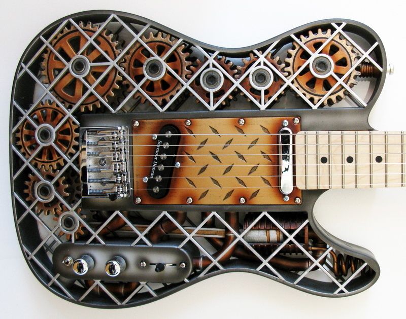
Step 1: Build the Frame
Source: https://www.pinterest.com/
The frame is the outer casing that houses the entire contraption, and it can be made to any size depending on what you need. The materials used to make the frame also vary, and the decision comes down to personal preference. The most compliant used materials are aluminum, acrylic, or hardened plastic. You have to make sure that all the parts fit well and there are no loose parts. It is important that the frame is solid because it will be providing support to the other parts that are added.
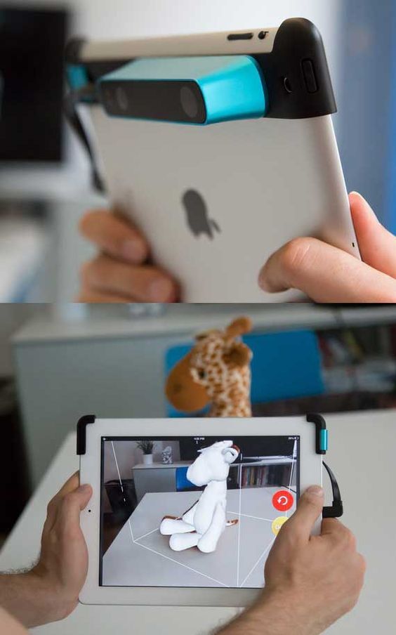
Step 2: The Display
Source: https://www.pinterest.com/
An LCD display is important as it relays the information you need to know about the printing process in the absence of a computer connection.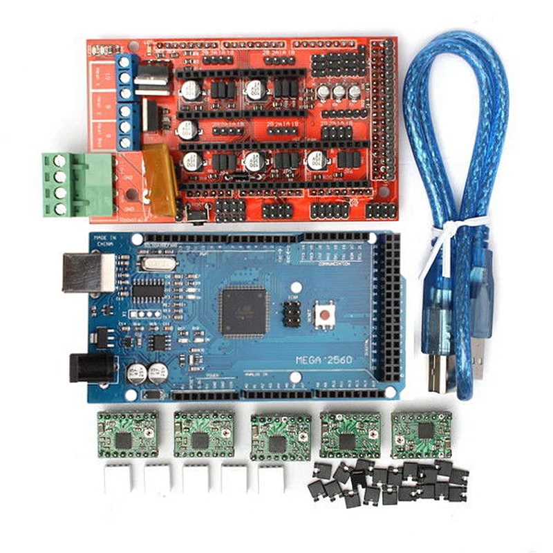 You need an aluminum sheet for this process with some holes and screws, and nuts. You have to cut out space into the aluminum sheet through which the display screen will pop out of. Once you have all that art covered, connect the necessary display cables from the inside leading out, waiting for the main part of the printer to be installed.
Step 3: Preparing the Y-axis and Z-axis
Source: https://www.pinterest.com/
You need an MDF base that houses a cooling fan to reduce the heat produced by the stepper motor. These are done by adding two wooden cuttings for the X-axis placement. This is followed by making the Y-axis placement that’s supposed to be at 90 degrees from the X-axis. Hold them in place using glue, or you can simply use some screws.
You have to add a stepper motor to the X-axis using two pieces of sliders of any length that can fit within the structure. Once the slide is screwed in place, fit your wooden mount for the hot-end, the cooling fan, and the PTFE tube.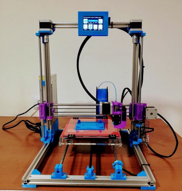 With these two in place, your 3D printer is starting to take shape.
Step 4: Preparing the Bed
Source: https://www.pinterest.com/
The bed is one of the most important parts of the entire machine. It is the part that provides the platform upon which the model being printed is made. It can be made out of glass or an acrylic sheet held down by screws. You can have the base supported by another solid material. Once all that is done, place the bed on the Y-axis, and it is ready to start rolling.
Step 5: Make the Connections
Source: https://www.pinterest.com/
The next part involves making the wiring connections of all the components that you have already laid down. All the electrical components like the ramps. The drivers and the power supply have to be linked properly for them to run as designed. To avoid entangling the wires, make sure you deal with one connection at a time, ensuring that they don’t cross each other unless there’s no other way around it.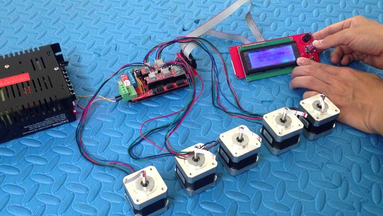
Step 6: Make Alignments
The bed you created earlier has to align with everything else, or you may experience a lot of trouble getting the models right. Start by aligning your bed, rotating it clockwise and counterclockwise until you create some space between the hot-end tip and the bed. The margin of error should be between 0.5mm to 1mm. Anything larger than that will have the printing guy misfiring.
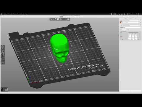
Step 7: Programming
Source: https://www.simplify3d.com/
With all the hardware installed and the electrical wiring and cabling in place. It is time to install the brain of the whole operation. Programming the 3D printer doesn’t require you to code from scratch. The software simply needs to be installed on the computer connected to the machine. This should not take too much of your time.
Step 8: Run the Machine
Once the 3D Printer program is installed and the components are set, it is time to run the machine for the first time to finger out if it is working as designed or whether it needs some more tinkling. The number of software that you can use to model your objects is many; you are free to choose the one that works best for you and switch the machine on for the first test run. Make sure the fan is working to deal with the heat.
Building Your Own 3D Printer. Is It Worth It or Not?
Source: https://www.pinterest.com/
Having established that making your own printer is possible, and having seen the process and what it takes to attain success, the question now is, is it worth the trouble? High-quality 3D printers cost less than $400 these days, and as much as making your own brings pride and cuts costs significantly, how do DIY 3D printers hold against professionally manufactured ones? To better get to the answer, the following are the pros and cons of DIY 3D Printers.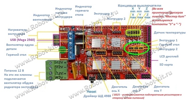
Pros
- DIY Kits are cheap and easy to access. For as little as $25, you can have a full package that can help you set up your own printer.
- DIY projects will make you understand 3D printing more, adding to your experience on the subject, which increases your level of knowledge and chances of success if you ever think of getting fully immersed into the industry.
- It is fast if you know what you are doing and you have all the materials you need in one place.
- There’s a huge online community of DIY 3D printer enthusiasts, and these platforms provide resources that help people learn more about 3D printing.
- The kits come with instruction manuals that anyone can follow and hack the construction. They are very easy to use.
Cons
- You still need some basic knowledge of assembling electronic parts in the right way to be able to put 3D printers together. You can’t wake up one morning and decide to make it because you feel like it.
- They are not as high quality as those that have been manufactured by proper 3D makers. The parts found in DIY printers are too rough and rudimentary for the machine to produce superior products.
- There are very many things you may miss along the way, and this can end up frustrating you later on as that will force you to retrace your steps backward until you find the source of the malfunction. That will waste a lot of your time.
- You will always need to buy more parts the furthest along you go. There’s also the disadvantage of the parts falling apart since they're not well optimized for such an intense process. You will need replacements much faster.
- There are limitations when it comes to software configurations and upgrades since the hardware is not optimized for the software you may choose to go with. You may end up using the same software for years, and that will limit the things the printer can pull off.
Roughly, you may end spending between $100-$200 making your own DIY 3D printer.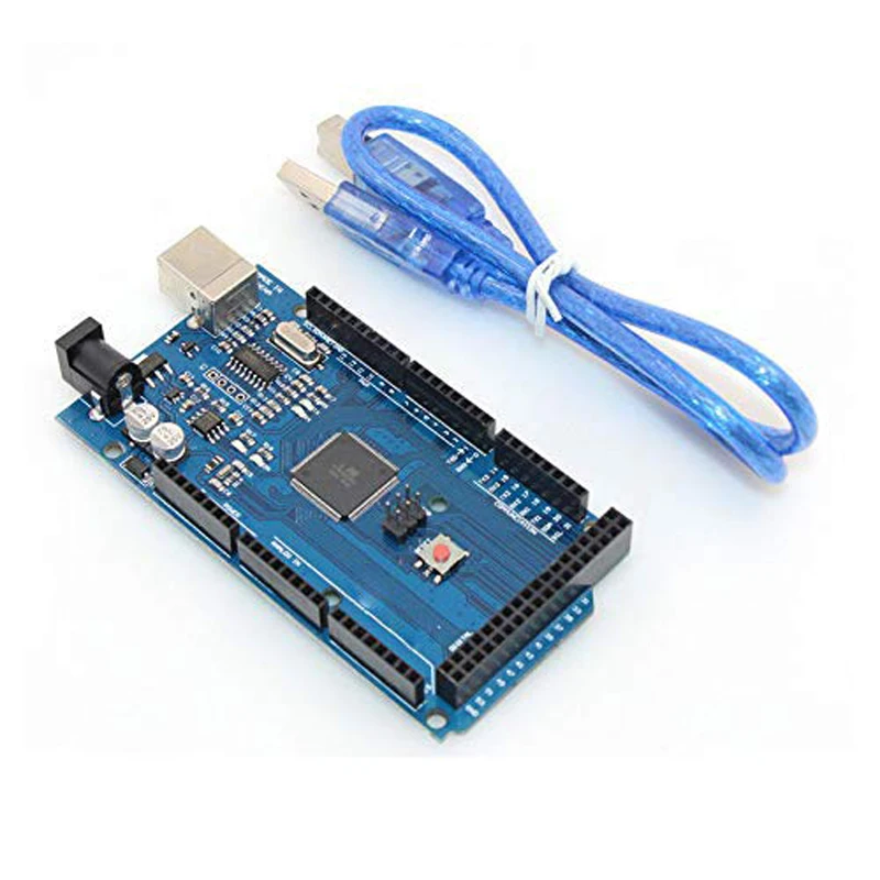 That cost may be cheaper than the standard prices for a professionally made printer, but when you weigh the strengths and weaknesses of each, the DIY is at a disadvantage. Therefore, on the question of whether to go for a DIY 3D printer or simply buy a good one, the answer comes down to what you plan to do. If the thrill of making your own is what is important, then take the DIY route. But if you want to get some professional work done, then you are better off adding that extra $200 and getting a proper 3D primer with accessories and software updates.
There are some things you have to pay attention to when going the DIY route, factors that will determine the success or the failure of your project. Some of them include the following.
- The size of the printer you intend to make
- The printer type (Cartesian vs. Delta)
- Extrusion type
- The cost
- Availability of liquid polymers
- Software compatibility.
Before you embark on setting anything up, you have to first determine whether all the conditions mentioned above are met; only then will you get anything done by coming up with a good plan.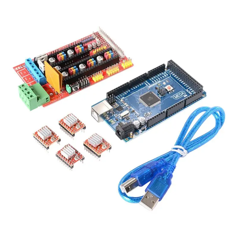
Conclusion
DIY 3D Printers are effective if they are made in the right way, and there are many methods of creating them. Finding a good Arduino kit could be the difference between having a 3D printer that world and one that keeps breaking midway. Ensure you do some background research before having to gain more knowledge before committing yourself to an ambitious project like this one.
For more information on how 3D printers work, the accessories they need to function properly, and the current trends in the industry, check out our website, and you will have access to a huge pool of resources and expert advice.
Build a 3D printer - Part 11: Electronics
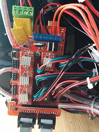
The brain of our 3D printer is the RAMPS 1.4 controller with Arduino MEGA 2560 board. In this part we will describe how to connect it to various components of our printer.
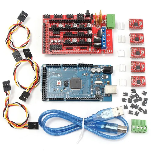
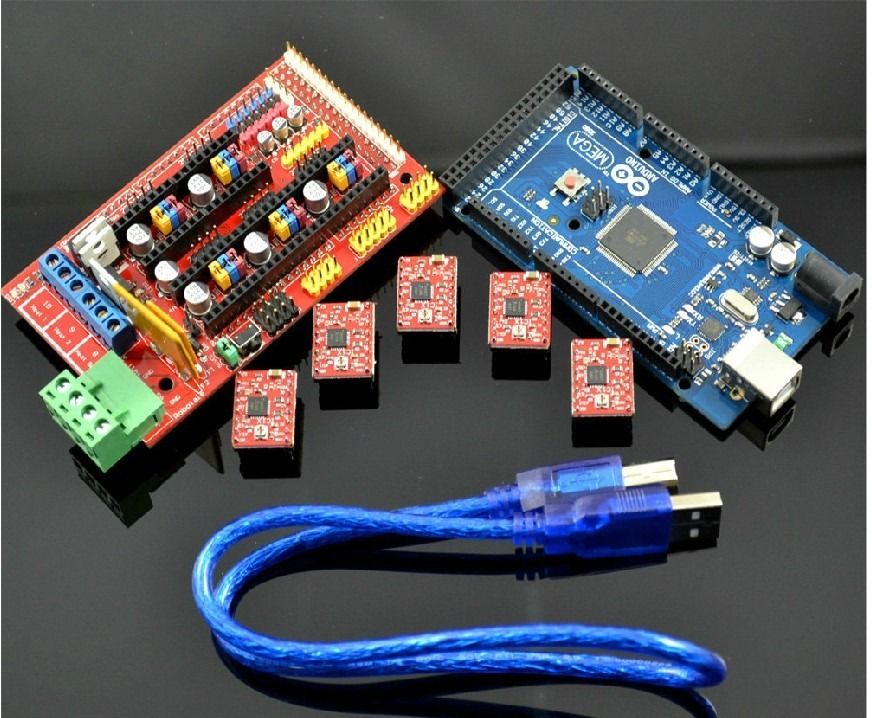
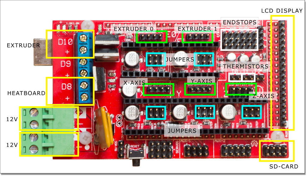
To start with we will need to build the complete controller. Beside the 2 boards mentioned above, we will need 15 jumpers and 5 pieces of A4988 stepper driver module.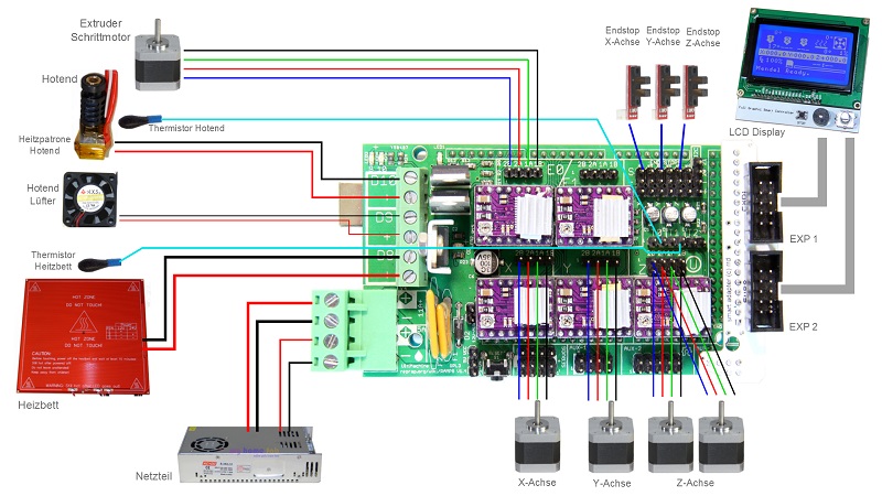 If you search for RAMPS 1.4 on eBay you can find compete packages that include all of the mentioned parts, but they are still not assembled. So, first place the jumpers on the RAMPS 1.4 board like this:
Next glue the heat sink on the chip of the modules.
The LCD 12864 board comes together with an attachment for the RAMPS 1.4 board.
Now place the A4988 modules together with the LCD link part on the RAMPS board. Notice the position of the stepper driver module. The way that I remember it, is that the current adjusting "screw" needs to be on the right, on the opposite side of the power inputs.
We are now ready to connect the stepper motors, endstops, thermistors, heatbed and extruder hotends. Initially we will connect the stepper motor outputs to the board. There are 5 sections on the RAMPS 1.4 controller. The bottom three ones are for the X, Y and Z axes and the other two are for the extruder stepper motors, named E0 and E1. First insert the connectors of X, Y and Z axes. Notice that the Z-axis has 2 outputs on the RAMPS board.
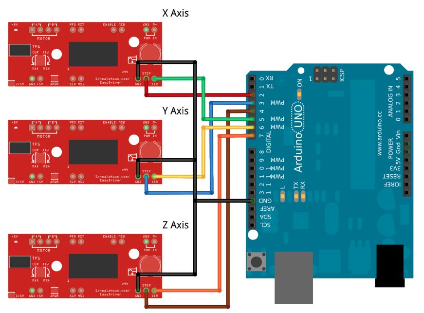
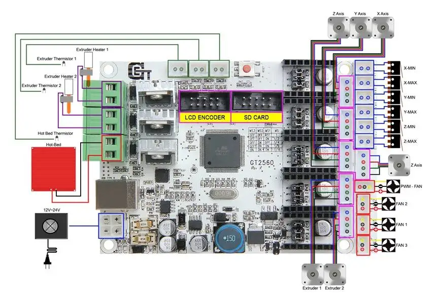
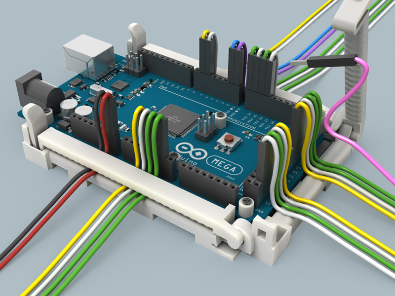
All the connections that we will make are based of this schematic overview.
This is how the stepper motors are connected to the board. The red wire is connects to 2B, blue goes to 2A, green to 1A and black connects to 1B.
Do the same for E0 (extruder 1) and E1 (extruder 2) outputs.
The picture below shows connections with the correct color codes.
Now let's connect the 3 endstops. The connections are located in the top right corner and the silk screen layer provides good descriptions +/- which is obvious and S for signal. Our endstop boards have a led to indicate when the switch is active, so we will need all 3 pinouts to connect them.
Make sure the red wire connects to + and the green wire connects to the signal (S) input. (Notice the reversed view of the board in the picture below)
To hook up the thermistors locate the connectors to the right of the board with T0, T1 and T2.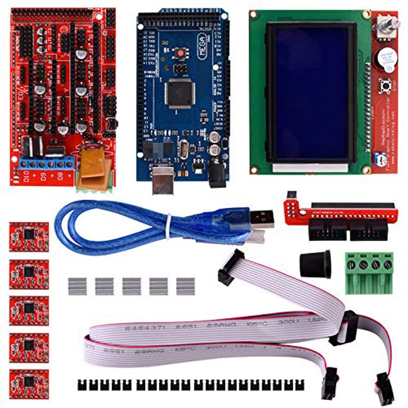
T0 connects to extruder 1 and T2 to extruder 2 thermistor. T1 is wired to the heatbed thermistor.
The hotends connect to D10 (for extruder 1) and D9 (for extruder 2). The heatbed connects to D8.
Because we are building a dual extrusion system, and usually the optional print fan is connected to D9 (which is actually the second extruder output), we will need addition output for this fan. This can be solved by adding RAMPS 1.4 RRD Fan Extender module.
The place to connected to the RAMPS board is shown in the picture below.
However, after we attach the board to the aluminum frame it will collide with one of the Z-axis stepper motors, so we will need to extend it with jumper connectors and some wire. I have combined 3x 4 pin output jumper connectors (female) and placed them on the board.
On the other end there are the opposite (male) connectors that connect to the RAMPS 1.4 RRD module.
On the opposite side of the RRD board there is a power input and 2 fans outputs.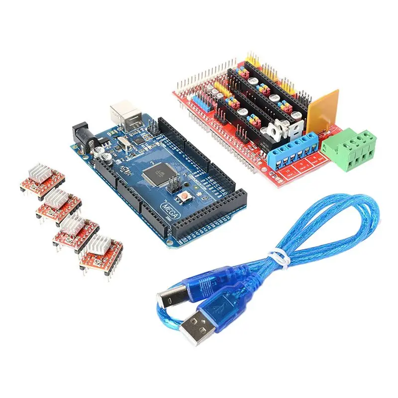 The red/brown wires (horizontal position) lead to the RAMPS board where they connect to the extruder fan. The red/black wired connectors (vertical position) are for the fans. Top one is for the extruder fan and the bottom one is the print fan, that will blowing on the 3D print to cool it. The fans will turn on and off when needed. It will be covered in the next parts of this blog series.
The extruder fan pinout on the RAMPS board are located to the left of the X-axis stepper motor outputs. Notice that the location of the positive red wire is on top (covered behind the brown wire in the picture below). Note that if you connect the RRD board incorrectly you will damage it!
We are finished to wire the board. In the next part we are going to connect the power supply and attach the RAMPS 1.4 controller board to the frame.
Category
Uno, Mega 2560, CNC Shield v3.0
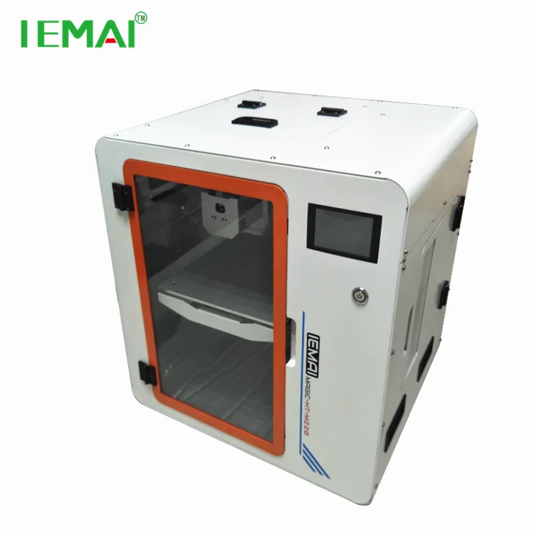
The 3D printer has found application in many areas. It is used both in industry and at home. But sometimes it’s not affordable to buy ready-made equipment, so those who want to get it have to decide to make a 3D printer on their own.
In this regard, there was a need for kits for the Arduino 3d printer. Their popularity is due to low prices for electronics and an acceptable level of performance of the assembled processor. Arduino is a brand of hardware and software tools for making automated robotic systems. The products of this brand are intended for non-professionals.
3D printer
The standard set consists of IDE (software shell) and hardware. The latter is a complex of mounted printed circuit boards, and they can be sold by both a third-party and an official manufacturer. They note the openness of the system architecture, which predetermines the constant addition and problem-free copying of the developed products.
What it's about:
- Parts
- How to Build an Arduino 3D Printer DIY
- Arduino UNO
- Arduino Mega 2560 for 3D printer
- Arduino CNC Shield v3.
 02
02 - Arduino Due
Components
Arduino boards are constructed from:
- microcontroller - it is a microcircuit designed for the microprocessor and peripherals;
- electrical outputs - they are distributed on the board and classified into analog (characterized by the presence of a range between 1 and 0) and digital (they have only two values 1 and 0).
Such a device makes the boards the universal core of the system in which they are included. IDE is a programming language designed specifically for Arduino.
How to build an Arduino 3D printer with your own hands
It is quite possible to make a 3D printer with your own hands, for this you need to follow the instructions that came with the Arduino kit. You can also be guided by the recommendations of professionals and methodological manuals.
Arduino 9 Board Design0003
3D printer consists of the following parts:
- body;
- controllers;
- guides;
- power supply;
- stepper motors;
- extruder.

The first step is to build the coordinate axes. To do this, you need drives, for example, from CD / DVD, which were on the computer. You also need to purchase a floppy drive, checking its performance is required. Its indicator is the step-by-step mode of operation, which is carried out without direct current. Next you need to choose stepper motors. The process of moving consumables requires a certain amount of power.
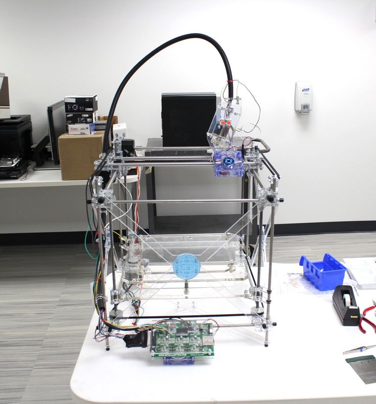
Arduino 3D printer
The next step is to choose the electronics. You will need the Arduino board itself, a cable, drivers (5 pieces), radiators, a power supply (suitable from a computer), a fan, limit switches (optical or magnetic), a heating table, a thermistor, a transistor, wires, plugs, a heating device for a hot end, nozzles and bowden. You can really buy them in a set, this will save time and effort without damaging the quality. You can find the assembly diagram of the parts on the Internet.
At the last stage, download the Arduino IDE, install the firmware (Marlin is more often used) and connect to the CNC controller.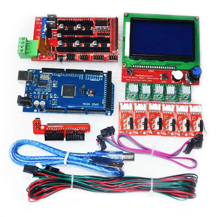 Having checked the assembly of electronics in this way, you need to decide on the software that will be responsible for controlling the 3D printer. An example in the photo.
Its functions include the acceptability of selected print parameters: infill, section height, and consumable layering speed. It remains only to assess the condition of the electrical wiring, assemble the last elements (frame, case, fasteners) in accordance with the instructions and connect the printer assembled by oneself to a PC.
Calibration of the 3D printer takes into account the diameter of the pulley, the number of steps per revolution of the motor and micro-steps in the electronics system. The result of the operation is the final configuration of the firmware.
Arduino UNO board
The Arduino UNO board works with the ATmega328 microcontroller, which is characterized by:
- 14 digital and 6 analog ports;
- USB ports;
- reset functions;
- in-circuit programming and power connectors.
The expansion board provides power to the above components, for example via USB. The location of the microcontroller facilitates its replacement and repair.
Arduino UNO has several differences from other modifications of the expansion boards of this company:
- Firstly, it does not need a USB-UART FTDI bridge to connect it to a PC.
- Secondly, it receives electricity through the USB port and with external devices. Several pins are predefined for this (Vin, IOREF, 5 V, GND).
- Third, the Arduino UNO microcontroller has three types of memory: FLASH, EEPROM, and SRAM.
- Fourth, there is a sequence in SPI. This applies from 10 to 13 exit (input).
- Fifth, there is an automatic reset function.
- Sixth, there is protection against the effects of wire heating.
Arduino UNO
Arduino Uno 3D printer is considered the most popular in its price category.
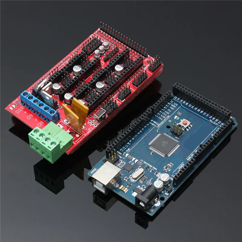
Arduino Mega 2560 for 3D printer
It is based on the Arduino Mega.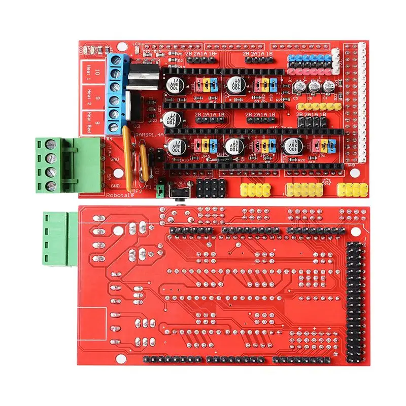 The Arduino Mega 2560 required an improved ATmega2560. The device has:
- 54 digital and 16 analog inputs;
- UART, USB;
- resonator;
- ISCP;
- reset function.
Mega 2560 board
The Arduino Mega 2560 is connected to a PC or to an external power source. The main differences of the innovation:
- No need for USB-to-serial.
- Resistor present.
- Adding SCL and SDA pins to the Arduino Mega 2560.
- Strengthening the RESET work sequence.
The Arduino Mega 2560 3d printer is a popular 3d printer available. This is due to the performance of his work.
Arduino CNC Shield v3.02
CNC Shield v3.02 expansion board designed for Arduino UNO 3D printers and similar equipment. This I/O base allows devices to operate in automatic mode or by connecting to a USB port.
Arduino CNC Shield v3.02
Arduino CNC Shield v3.02 has 4 axes, two kinds of interface (UART, I2C).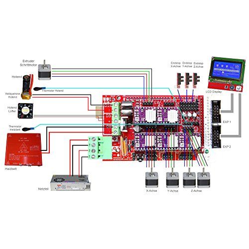 The required voltage for the power and logic parts is 36 V and 5 V, respectively. The firmware type of this board is called Arduino GRBL. The base is characterized by four slots (according to the number of axes) and jumpers for their duplication. Arduino CNC Shield v3.02 drivers are connected in different ways.
Arduino Due
The Arduino Due is a board based on the Atmel SAM3X8E ARM Cortex-M3 processor. Device present:
- 54 digital and 12 analog pins;
- UART;
- DAC;
- TWI;
- HTS;
- JTAG, SPI;
- Erase and reset functions.
Arduino Due - board
Do-it-yourself assembly of a 3D printer should be carried out only after accurate planning of actions. The process will facilitate the purchase of a complete set from an official manufacturer.
Bringing Arduino Mega 2560 + RAMPS1.4 to mind
Hello comrades.
Topics with jambs RAMPS pop up all the time.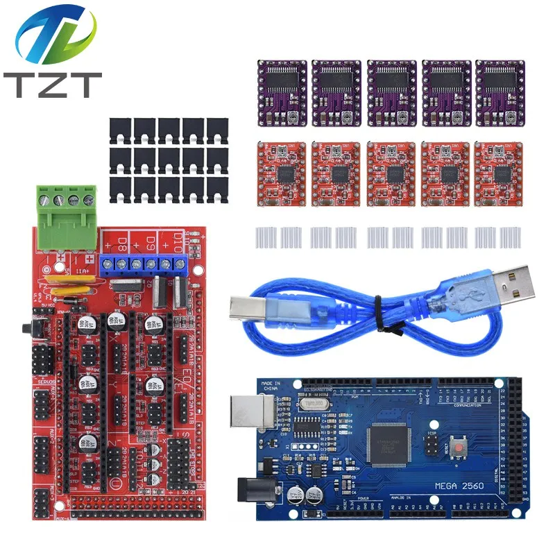 There are many solutions to these jambs, but everything is scattered across the comments and forums. In the process of collecting and applying this information, it was killed: Arduin 1 pc, Ramps 1 pc, about a dozen transistors. The result of my torment was that for half a year I had not looked into the electronics compartment due to the failure of something.
As you already understood, we will talk about a common set of Arduino Mega 2560 + Ramps 1.4. Probably the most common and, for sure, the most affordable electronics kit for a 3D printer.
[IMG ID=32274 WIDTH=199 HEIGHT=199][IMG ID=32275 WIDTH=193 HEIGHT=193]
In this post, I'll describe step by step what I did with a description of how to do it. Whether to follow these points (all or some) is up to you. Also, I am not responsible if you burn something there. I also warn you that I am not an electronics engineer, everything described here was not invented by me. I just want to put together the most, in my opinion, successful and necessary alterations.
So let's start.
1. The first thing I recommend to do is to throw out the green connector from the RAMPS. If you follow further advice, it will not be needed. But even if not, just throw it away and solder wires in its place. This connector is too weak for the current required to power the table. Over time, it will melt, which will lead to sad consequences.
If you remake the power supply of the table according to the instructions in point 3, then you need to solder only two wires instead of the green connector. On the board under the connector, the power contacts are numbered. Contact number 4 is a minus. Number 3 is a plus. We solder the wires to them and connect them to the power supply.
2. Remove diode D1 from RAMPS. This will separate the power of the RAMPS, and accordingly the motors, drivers and everything else, from the power of the Arduino. Why this is necessary will be clear from the following paragraphs.
[IMG ID=32276 WIDTH=393 HEIGHT=230]
3. Now, probably, the most important and necessary item. Questions about it pop up at least once a month. Organization of normal meals of the table.
What you need:
- First of all, you need a normal power transistor. Those that the Chinese put are not suitable, although they work. Suitable transistor models: IRL 3705n, IRL2203n, IRL3803, IRL2505. Choose what is the cheapest in your radio products (the price is usually from 30 to 100 rubles), if there is none of this, look for analogues in Google, there are a lot of them. The parameters should be as follows: drain current from 30A, the higher the better, source-drain voltage from 25V, gate voltage 4.5V, TO220AB case. I understand that seasoned electronic engineers will attack me with shouts, that these are far from all the important parameters, but I selected them according to them and everything works for me, so why should I climb into the jungle?
- Wires. I use Chinese 14AWG wires. They are enough and they do not heat up.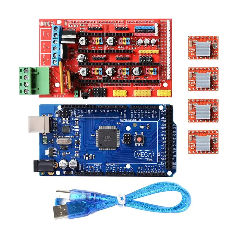 Look for a plate of correspondence with our sections in Google.
- Soldering iron from 60 watts. RAMPS is quite difficult to solder, or rather to solder out of it. So practice on the old mainland.
- Aluminum radiator. Sizes from 20x20x20mm and above. You can do without it, more on that below.
- Any small items for soldering, solder, flux, heat shrink, etc. If you don't know what it is, don't take it.
Now directly to the process:
The first thing to do is to unsolder the table's native power transistor.
[IMG ID=32278 WIDTH=307 HEIGHT=307]
We won't need it anymore. You can, of course, use it, but it will get very hot even on a radiator, so it's easier to buy a normal transistor for 50r.
Now, instead of the leg, which is located closer to the large orange fuses, you need to solder either the wires (you can use any thin wire) or, as I did, a pin like those located at the edges of the RAMPS. You can take it from any old motherboard (yes, there are many where they are used). I soldered the pin so that I could turn it off at any time without worrying about soldering RAMPS.
We are done with RAMPS for now. Let's start with the transistor.
Everything is connected quite simply.
- From the left leg (shutter) the wire connects to the RAMPS, to the same pin. The connector for such contacts is sold under the name BLS-01.
- The central leg (drain) is connected to one of the contacts of the table (polarity is not important for the table).
- The right leg (source) is connected directly to the MINUS power supply.
All wires are carefully soldered and insulated with heat shrink.
From the second contact of the table, the wire is connected directly to the PLUS power supply. I pay close attention to the polarity of the connection. The table does not care where you connect the plus and minus, but the transistor does not.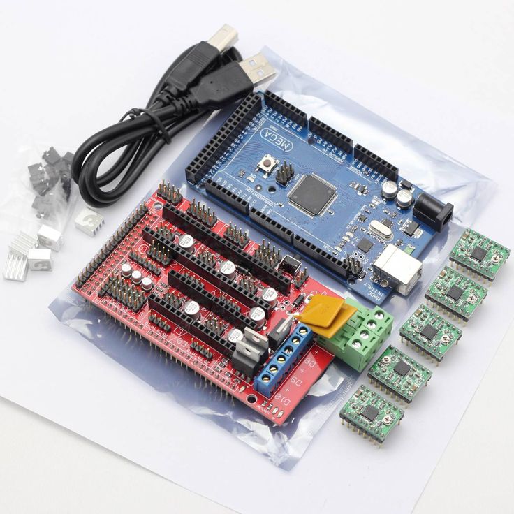 The transistor should hang on the negative line.
Now it remains to screw or glue the transistor to the heatsink. I made it easier, screwed the transistor through thermal paste directly to the power supply case into the standard hole. Fortunately, the PSU case is aluminum. Now the transistor is always cold.
As a result of this alteration, we started the table power bypassing the RAMPS. From RAMPS only a signal goes to the gate of the transistor. The power for the rest of the electronics (except for Arduino) still goes through the RAMPs along the wires that we soldered in step 1. Please note that the negative wire from the RAMPS and the wire from the right leg (source) of the transistor must be connected to the same negative contact of the block nutrition.
4. Now let's talk about the Arduino power supply. In paragraph 2, I recommended to separate the power supply of Arduino and RAMPS. There are two reasons for this.
Firstly, 12 volts for the Arduino converter is a lot, this is its limit value and at this voltage it does not heat up slightly and can burn out. Especially if you connect additional consumers, such as a display.
Secondly, this will increase the supply voltage of the RAMPS above 12 volts.
Why raise the RAMPS supply voltage. There is only one reason - to speed up the heating of the table. At 12V, the table heats up for a long time. The time depends on the specific instance, or rather on its resistance. It can take up to 15 minutes, which is a very long time. There is, of course, an option with altering the table to a lower resistance, but, in my opinion, it is easier to tweak the voltage on the PSU. I set my PSU to 15V. At the same time, I have a standard 12V heater on the hot end and the table is connected according to the 12V circuit. The table heats up to 100 degrees in 4-5 minutes without any insulation. The only thing I had to do was to run a PID test on the M303 command to even out the temperature of the hot end. Despite the increased supply voltage of the hotend heater, the temperature is kept within +-0.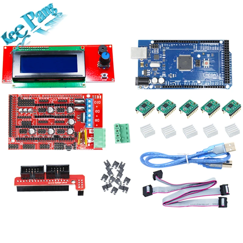 5 degrees from the set one.
How to power the Arduino? There are two options.
First, power it from USB. The most simple and inconvenient. I've been using the printer this way for quite some time. If you print from a computer, do not connect additional equipment to the Arduino (server, display), then it is quite a working option. About the disadvantages of such a connection, I think, it’s not worth talking about.
Second option, DC-DC buck converter. Here's one.
[IMG ID=32280 WIDTH=226 HEIGHT=226]
Worth a penny. Connecting is very simple. The IN pins are powered by the PSU, the OUT pins are powered by the round Arduino connector. First you need to set the voltage output by the converter to 7-9 Volts. This is the optimal voltage for the Arduino native converter. For greater reliability and space saving, I removed the round connector from the Arduino and soldered the wires from the converter directly to the board. Now, when you connect a display with a card reader, the printer becomes autonomous from the computer.