3D printer software for arduino
How to Make a 3D Printer with Arduino – ELEGOO Official
Source: https://unsplash.com/
3D printing technology is wide, despite having been around for a little over 30 years. The improvements the technology has been undergoing are all slowly pushing it slowly towards a realm where everyone will be able to access simple 3D printers at low prices, getting the ability to make whatever they want from the comfort of their own homes. One of the most utilized 3D printing concepts is the Arduino.
Arduino is an open-source electronics platform that is based on easy-to-use software and hardware. They are boards that have the ability to read inputs, activating other machines, among many other automated functions. We are going to explore how to make a 3D printer using the Arduino platform, the benefits of having a DIY Arduino printer as well as some comparisons with other official models that are in the market.
Why Arduino?
Source: ELEGOO
There are perfectly good reasons why Arduino is used extensively in most DIY projects of making 3D Printers. The first Arduino kit was created in 2005, and in the last 15 years, it has become a very reliable software for people who are looking to create their own 3D printer. The following are reasons why they are the best choice for DIY 3D Printers.
- It is cheap: Arduino is easily accessible and affordable, and the price keeps going down as more improvements are being made in the 3D printer sector. A simple Arduino kit will set you back just about $24, which is well within the affordable range of most people.
- Easy to use: An Arduino kit is usually ready to use straight from the box. The kit comes in a complete package that includes a 5V regulator, a burner, a microcontroller, a serial communication interface, LED, and headers. All you have to do is plug it into the USB port of a computer, and you are ready to roll.
- Wide range of codes: Arduino comes with a huge library of codes that are already present in the Arduino itself. The kit literally sets itself up in a number of ways, and in the event, you run into obstacles, troubleshooting is not that complicated to pull off on your own.

- Large community: There is a huge number of online forums that are full of people who use Arduino, and this provides new users with a platform where they can get help immediately from other users who have had the experience already. Every trouble you may run to will have a solution, and this makes Arduino a very resourceful tech.
- Cross-platform: Arduino is a cross-platform software that can be used on Windows, Linux, and Mac. This makes it resourceful and unlimited in many ways. You don't have to buy a particular computer to run it; all you need is to get a computer with the right specs. You will be making your 3D models in no time.
Making a 3D Printer with Arduino
The process of making a 3D printer may look daunting for those that have never used it before, but if you are a newbie to the game, the process is a little easy.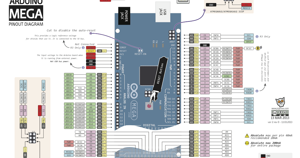 The following are some of the stages that are used in making a 3D printer using the Arduino platform.
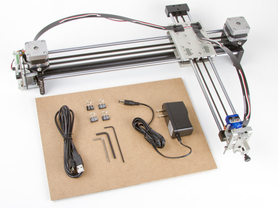
To start off, you have to start collecting the components and supplies to start yourself off. The following are the boxes you have to tick off.
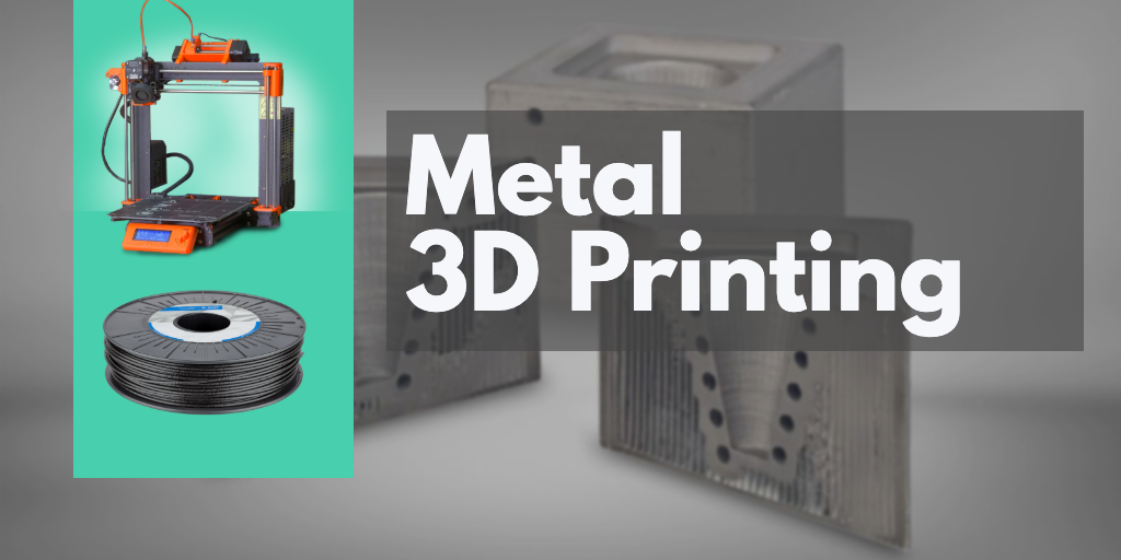
- A ramps 1.4 controller board: This is used for interfacing purposes like connecting the end-stop switch, the heatbed, the stepper motor driver, the hotend, and a host of other components with the Arduino.
- Optical end-stop switch: This is a sensor switch that comes with two markings. NO or NC (Normally Open/Normally Closed). They function as triggers when the XYZ axis of a printer reaches its endpoint. They can be used at any time to stop and start movements.
- NEMA 17 stepper motor: This is a motor that allows the user to set the speed of revolutions for the movable parts of the printer. The average motor has about 200 steps, but you can get a bigger one.
- PCB heatbed: This keeps the extruded plastic parts warm at all times to prevent them from warping.
- Power supply: A 12V/20A power supply is needed to run a simple kit. These power metrics are the minimum you should go for success.
The Process
With all the important components in place, the next step is to start making your DIY 3D printer. The stages involved include the following.
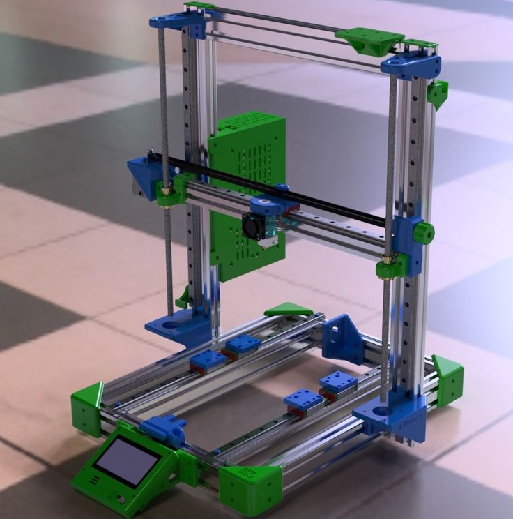
Step 1: Build the Frame
Source: https://www.pinterest.com/
The frame is the outer casing that houses the entire contraption, and it can be made to any size depending on what you need. The materials used to make the frame also vary, and the decision comes down to personal preference. The most compliant used materials are aluminum, acrylic, or hardened plastic. You have to make sure that all the parts fit well and there are no loose parts. It is important that the frame is solid because it will be providing support to the other parts that are added.
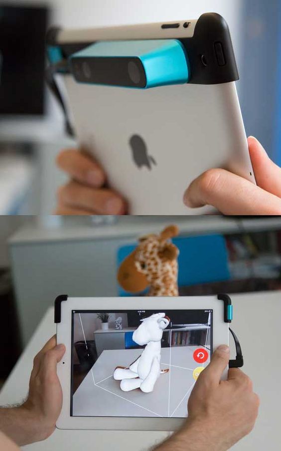
Step 2: The Display
Source: https://www.pinterest.com/
An LCD display is important as it relays the information you need to know about the printing process in the absence of a computer connection.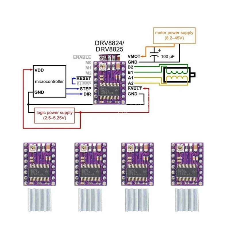 You need an aluminum sheet for this process with some holes and screws, and nuts. You have to cut out space into the aluminum sheet through which the display screen will pop out of. Once you have all that art covered, connect the necessary display cables from the inside leading out, waiting for the main part of the printer to be installed.
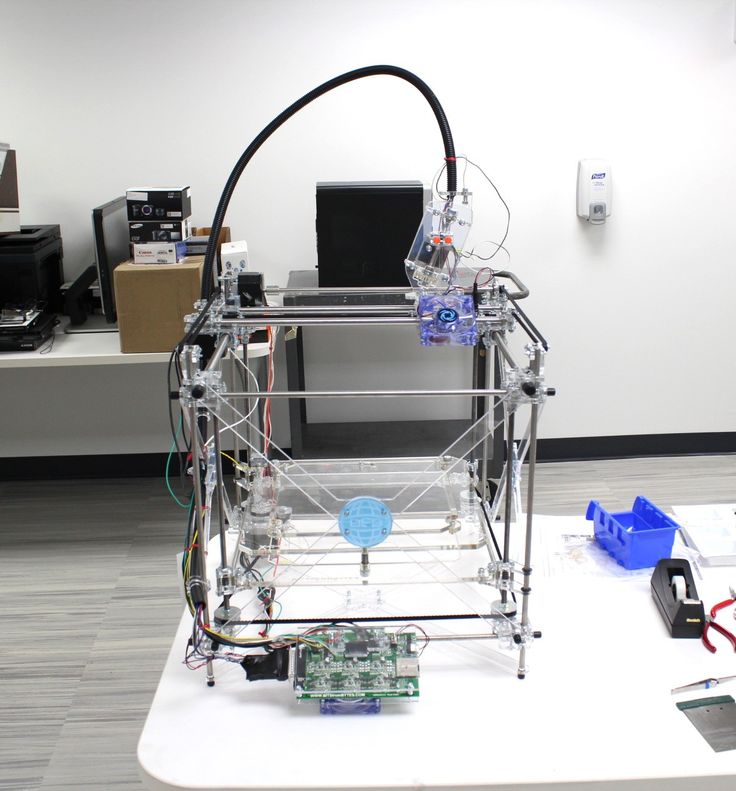
Step 3: Preparing the Y-axis and Z-axis
Source: https://www.pinterest.com/
You need an MDF base that houses a cooling fan to reduce the heat produced by the stepper motor. These are done by adding two wooden cuttings for the X-axis placement. This is followed by making the Y-axis placement that’s supposed to be at 90 degrees from the X-axis. Hold them in place using glue, or you can simply use some screws.
You have to add a stepper motor to the X-axis using two pieces of sliders of any length that can fit within the structure. Once the slide is screwed in place, fit your wooden mount for the hot-end, the cooling fan, and the PTFE tube.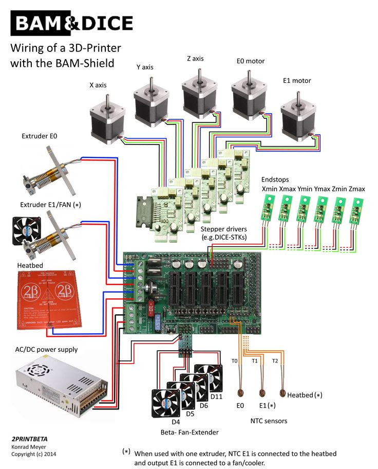 With these two in place, your 3D printer is starting to take shape.
Step 4: Preparing the Bed
Source: https://www.pinterest.com/
The bed is one of the most important parts of the entire machine. It is the part that provides the platform upon which the model being printed is made. It can be made out of glass or an acrylic sheet held down by screws. You can have the base supported by another solid material. Once all that is done, place the bed on the Y-axis, and it is ready to start rolling.
Step 5: Make the Connections
Source: https://www.pinterest.com/
The next part involves making the wiring connections of all the components that you have already laid down. All the electrical components like the ramps. The drivers and the power supply have to be linked properly for them to run as designed. To avoid entangling the wires, make sure you deal with one connection at a time, ensuring that they don’t cross each other unless there’s no other way around it.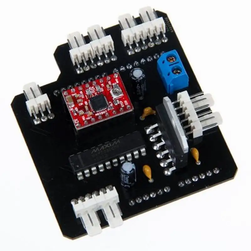
Step 6: Make Alignments
The bed you created earlier has to align with everything else, or you may experience a lot of trouble getting the models right. Start by aligning your bed, rotating it clockwise and counterclockwise until you create some space between the hot-end tip and the bed. The margin of error should be between 0.5mm to 1mm. Anything larger than that will have the printing guy misfiring.
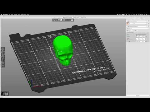
Step 7: Programming
Source: https://www.simplify3d.com/
With all the hardware installed and the electrical wiring and cabling in place. It is time to install the brain of the whole operation. Programming the 3D printer doesn’t require you to code from scratch. The software simply needs to be installed on the computer connected to the machine.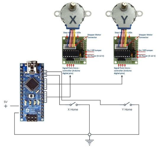 This should not take too much of your time.
Step 8: Run the Machine
Once the 3D Printer program is installed and the components are set, it is time to run the machine for the first time to finger out if it is working as designed or whether it needs some more tinkling. The number of software that you can use to model your objects is many; you are free to choose the one that works best for you and switch the machine on for the first test run. Make sure the fan is working to deal with the heat.
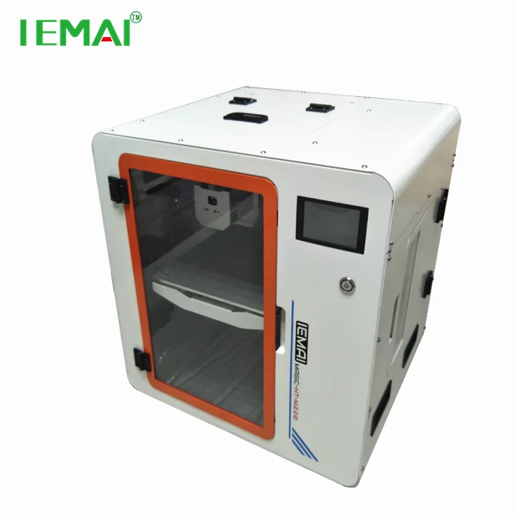
Building Your Own 3D Printer. Is It Worth It or Not?
Source: https://www.pinterest.com/
Having established that making your own printer is possible, and having seen the process and what it takes to attain success, the question now is, is it worth the trouble? High-quality 3D printers cost less than $400 these days, and as much as making your own brings pride and cuts costs significantly, how do DIY 3D printers hold against professionally manufactured ones? To better get to the answer, the following are the pros and cons of DIY 3D Printers.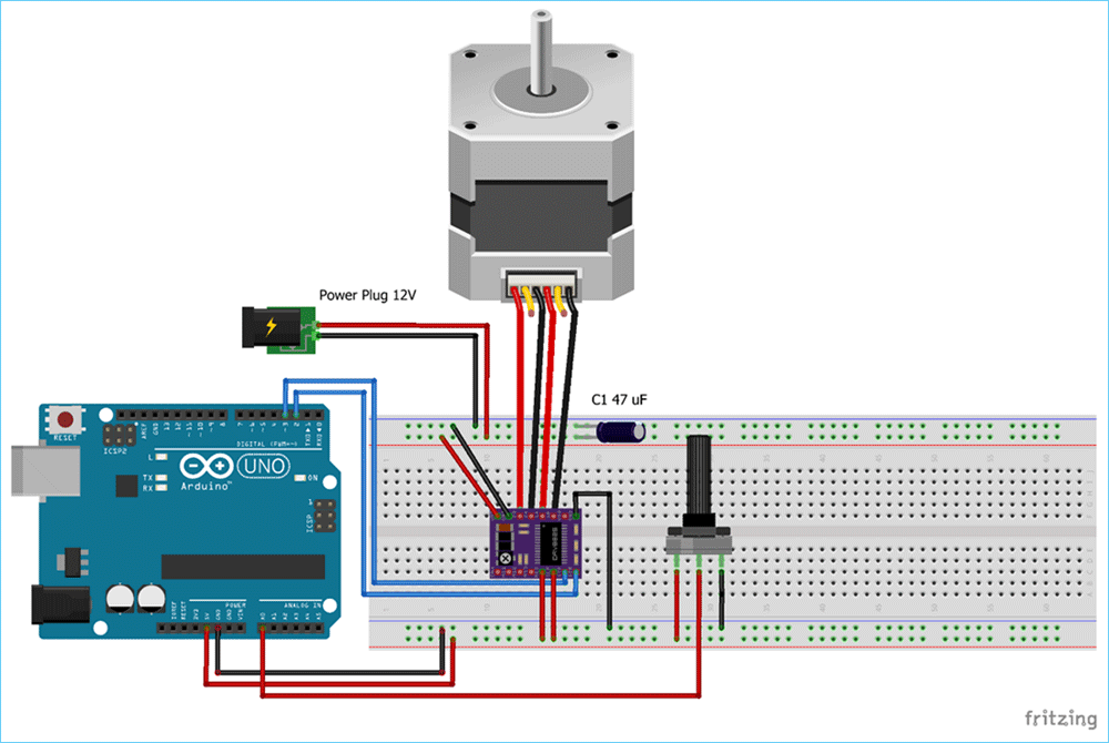
Pros
- DIY Kits are cheap and easy to access. For as little as $25, you can have a full package that can help you set up your own printer.
- DIY projects will make you understand 3D printing more, adding to your experience on the subject, which increases your level of knowledge and chances of success if you ever think of getting fully immersed into the industry.
- It is fast if you know what you are doing and you have all the materials you need in one place.
- There’s a huge online community of DIY 3D printer enthusiasts, and these platforms provide resources that help people learn more about 3D printing.
- The kits come with instruction manuals that anyone can follow and hack the construction. They are very easy to use.
Cons
- You still need some basic knowledge of assembling electronic parts in the right way to be able to put 3D printers together. You can’t wake up one morning and decide to make it because you feel like it.
- They are not as high quality as those that have been manufactured by proper 3D makers. The parts found in DIY printers are too rough and rudimentary for the machine to produce superior products.
- There are very many things you may miss along the way, and this can end up frustrating you later on as that will force you to retrace your steps backward until you find the source of the malfunction. That will waste a lot of your time.
- You will always need to buy more parts the furthest along you go. There’s also the disadvantage of the parts falling apart since they're not well optimized for such an intense process. You will need replacements much faster.
- There are limitations when it comes to software configurations and upgrades since the hardware is not optimized for the software you may choose to go with. You may end up using the same software for years, and that will limit the things the printer can pull off.
Roughly, you may end spending between $100-$200 making your own DIY 3D printer. That cost may be cheaper than the standard prices for a professionally made printer, but when you weigh the strengths and weaknesses of each, the DIY is at a disadvantage. Therefore, on the question of whether to go for a DIY 3D printer or simply buy a good one, the answer comes down to what you plan to do. If the thrill of making your own is what is important, then take the DIY route. But if you want to get some professional work done, then you are better off adding that extra $200 and getting a proper 3D primer with accessories and software updates.
There are some things you have to pay attention to when going the DIY route, factors that will determine the success or the failure of your project. Some of them include the following.
- The size of the printer you intend to make
- The printer type (Cartesian vs. Delta)
- Extrusion type
- The cost
- Availability of liquid polymers
- Software compatibility.
Before you embark on setting anything up, you have to first determine whether all the conditions mentioned above are met; only then will you get anything done by coming up with a good plan.
Conclusion
DIY 3D Printers are effective if they are made in the right way, and there are many methods of creating them. Finding a good Arduino kit could be the difference between having a 3D printer that world and one that keeps breaking midway. Ensure you do some background research before having to gain more knowledge before committing yourself to an ambitious project like this one.
For more information on how 3D printers work, the accessories they need to function properly, and the current trends in the industry, check out our website, and you will have access to a huge pool of resources and expert advice.
How can I program a 3D printer to move using Arduino?
Ask Question
Asked
Modified 4 years, 9 months ago
Viewed 8k times
$\begingroup$
I search about that topic, but all what I found, was the mechanical part of the 3d printer.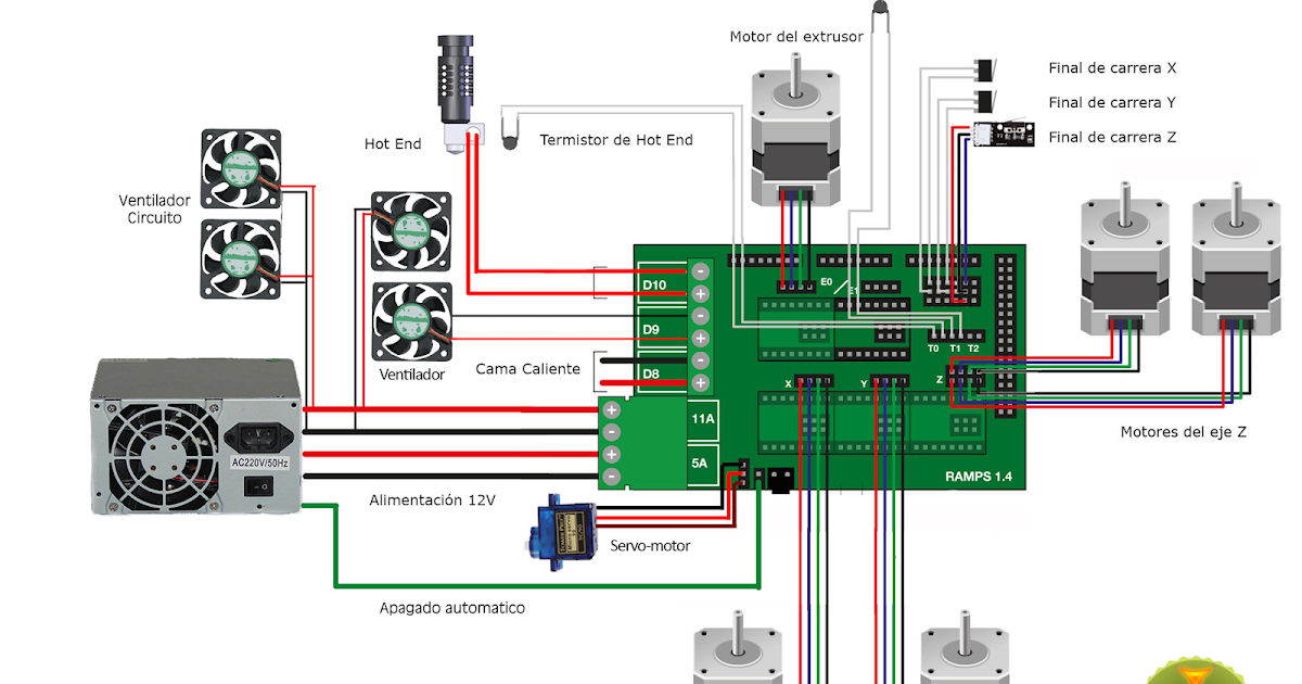 But I didn't find, how to program it using arduino.
I want to make a cartesian 3d printer. I don't have a printer yet, but I will buy all the components that I need actually.
I know, how to control stepper motors, but I don't know, how I can program it in order to make the shape that I want.
This is my question: what I need to learn in order to let this 3d printer make this shapes?
- arduino-mega-2650
- diy-3d-printer
$\endgroup$
6
$\begingroup$
Yes. Look up Arduino Ramps 1.4
http://reprap.org/wiki/RAMPS_1.4
Following the programing is all done for you in the firmware. That said you can edit it. Just open the firmware files -- it is compiled when you upload them. Generally however one usually sticks to the preferences header alone..
http://reprap.org/wiki/List_of_Firmware
Over all you are trying to reinvent the wheel. When I started 5-6 years ago it was barely a thing. Now you buy a proven kit and get to the printing. That said if you are truly interested in designing check out.
https://www.facebook.com/groups/cncbuilddesign/
If you want help on picking a kit. Or what I really think you are looking for. A good place to start. This is one of the larger 3d printing groups. Full disclosure I run this one, but at 6k members I don't recruit.
https://www.facebook.com/groups/3DPrinterHobbyists/
I got my start in reprap IRC
http://reprap.org/wiki/IRC
Be aware there are trolls that now camp the IRC looking to sell you a printer. I would not engage with them, their printers are usually overpriced and sub par.
Best of luck.
Most of all I think you need to know it's Reprap all the way. Reprap forums, Reprap printers, Reprap kits, Reprap community. All the commercial printers started off the reprap project. Even if you buy a makerbot (don't) it's Reprap in it's roots.
https://vimeo.com/5202148
$\endgroup$
$\begingroup$
While Star Wind's answer is best as far as addressing what was not asked, but was probably the intent of the question, for educational purposes:
To control the printer you need an microcontroller (most popular are Arduino) which will interface with the motor drivers. Microcontrollers cannot output the current needed to control the motors, so motor drivers (such as this https://www.pololu.com/product/1182 ) are easy ways to control a stepper motor with higher current (and usually voltage). You can build your own if you are particularlly adventurous, they are essentially two H-bridge circuits.
The Arduino programming environment has a library for controlling stepper motors through a driver built in, you just tell it which pin to send the pulses to, and how fast, and a separate pin tells it to spin clockwise or counterclockwise.
For a 3D printer you need at least four motors working in unison, one for the X, Y, Z axis, and one for the extruder (E axis).
The existing programs that 3D printers use (Marlin, Sprinter, Teacup, etc) are all doing these simple steps at their core, but have implemented libraries of G-code that the printer uses to make control the stepper motors in unison to make the correct shape. Slicing programs such as Cura or Slic3r take in the 3D model and output the Gcode that the microcontroller is programmed to understand.
$\endgroup$
1
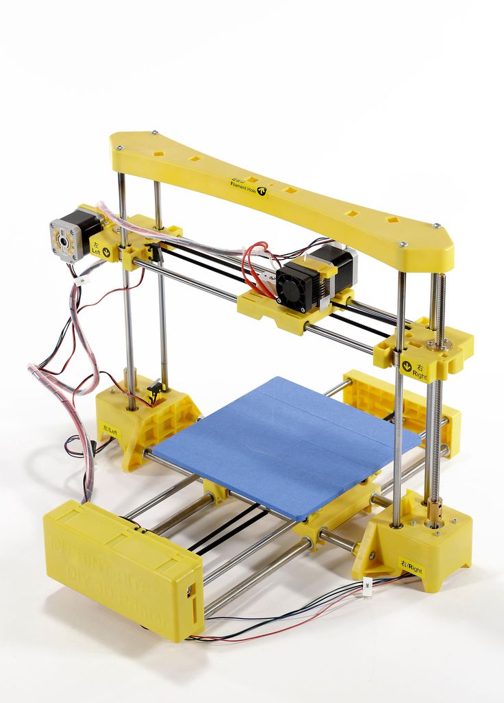
Cheap Arduino 3D Printer||Arduino-diy.com
This article describes the construction of a 3D printer that costs around $60-70 (probably the cheapest concept in the world).
This 3D printer works with the cheapest motors on the market - 28Byj-48, Electronics - Ramps 1.4 controlled by Arduino.
The author of the project is a 16-year-old guy from Germany.
3D printer specifications:
Working space: 10x10x10 cm;
Speed: 20 mm/s;
Resolution (accuracy): 0.2 mm.
P.S. Under each section, in accordance with the table of contents of the article, photos are posted as a visual instruction
Mechanical part
MDF boards:
-1x 30x34 cm (Base).
-2x 6x4 cm.
-1x 34x6 cm.
-1x 15x4 cm.
- 2 GT2 pulleys + 1 m GT2 timing belt.
-10 bearings 624.
-1 pulley Mk8 for drive.
-1 PTFE tube.
Smooth rods for guides with a diameter of 8 mm:
- 2, 22 cm long.
- 4 x 17.5 cm long.
Local hardware store:
- 1 shaft with M5 thread, which you will cut into 2 pieces.
-2 M5 hex nuts.
- 8 screws M3x16 mm.
-6 screws M3x 25 mm.
-4 screws x M4x45 mm.
-2 screws M4x60 mm.
-4 screws M4x20 mm.
-20 M4 hex nuts.
-10 M3 hex nuts.
-12 small screws.
Electronics
-1 Arduino Mega 2560 board + Ramps 1.4 + 4 A4988 stepper motor drivers.
-4 stepper motors 28byj-48.
-3 optical limit switches.
-1 Nema 17 stepper motor (we also order from Ali or Ebay. Such drives cost about 10 dollars).
Extruder tip:
-1 E3D-V5 Aliexpress extruder
or more expensive but with cooling
-1 E3D-V6 Aliexpress extruder.
Knots to be printed on a 3D printer
Download the latest versions of 3D models of units to be printed from the link: Thingiverse
.
2 "Z-Motor" parts
2 "Y-End" parts
2 "X-End" parts
1 "X-Carriage" part
1 "Motor" part
1 "Hotend" part
1 piece "Hotend Clamp"
Download mechanism for extruder here: Thingiverse.
28BYJ-48 Stepper Motor Modification
In order to convert the 28BYJ-48 stepper motor from unipolar to bipolar, you need to open the plastic cover.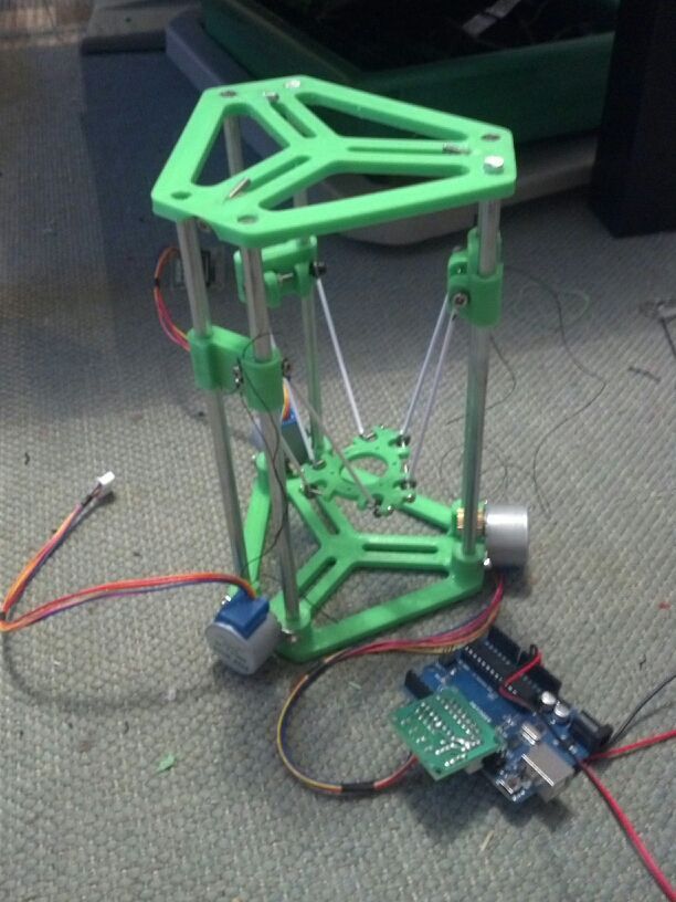
Then remove the red cable and open the contact track from it as shown in the figure.
Now at the other end is the output that you will connect to the Ramps, arrange the pins as follows:
blue--yellow--orange--pink
With this little modification, you can connect these motors directly to the pins provided on the Arduino Ramps 1.4 shield
Y Axis
First you need to glue two wooden boards together.
Then place the printed parts "Motor", "Z-Motor" on the wooden boards.
Then fix the printed parts with the screws.
Next step: fit the motors into the slots and then the LM8UU bearings.
Install the pulley on the motor and the 624zz bearings next to it.
Use plastic ties to secure LM8UU bearings.
Next - install two guide rails 17.5 cm long with a diameter of 8 mm.
Finally, pull the belt through the "Y-ends" and install the limit switch.
X-Axis
For X-Axis you need:
Install two M4x45mm bolts in the "X-End".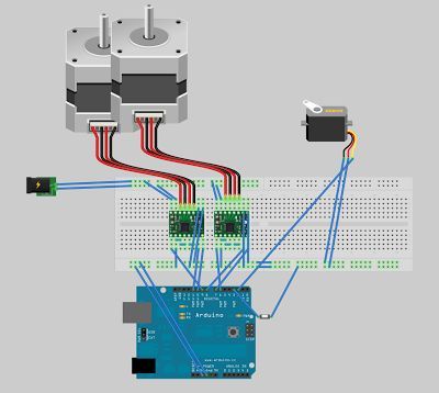
Connect the motor as shown in the illustrations.
Tension the belt and install the limit switch.
Mount the extruder with two screws M3x25 and tighten with nuts.
Z Axis
In order to assemble the Z axis, you need:
Install LM8UU bearings in "X-Carriage" + "X-Ends".
Post install "X-Ends" + "X-carriage" on rails 17.5 cm (X-Axis) and 21cm (Z-Axis).
After that it is necessary to connect the threaded shaft with the motor
Printing table
We drill four holes with a diameter of 3 mm in a wooden plate 20x13 cm.
After that we tighten 4 bolts M3x25.
We assemble the entire 3D printer
We assemble it in accordance with the figures below. There is no point in giving additional explanations. The main thing is that the previous steps are correctly implemented. In this case, there should be no problems.
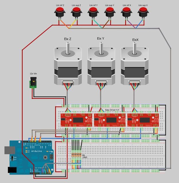
We connect electronics to the 3D printer
We connect electronics (including Arduino) in accordance with the figure below.
Software for Arduino
You can download the Arduino IDE configuration file from www.repetier.com.
This should be enough. You can carry out direct adjustment for your received design, dimensions, etc.
Photo of the printing process and results
After some calibration, good cube samples were printed with dimensions of 1x1x1 cm. As a result, there is a significant displacement of the layers.
So I recommend setting the A4988 to 1/16 microstepping and adjusting the current to the minimum value.
You can also play around with the Arduino firmware to get better results.
Leave your comments, questions and share your personal experience below. In the discussion, new ideas and projects are often born!
We assemble a 3D printer with our own hands. Step-by-step instruction. Part 4.
Friends, hello!
At the end of today's part, our printer will be printing.
Let me remind you what we have already done:
1. Introductory. Purchasing everything you need. 2. Assembling the printer. Part one. Body and mechanics. 3. Assembling the printer. Part two. Electronics. 3.1. Additional photos. 3.2. Connecting the electronics 4. Firmware and printer setup - Marlin.
5. Firmware and printer setup - Repetier-Firmware.
Today we need a multimeter, a computer, the USB cable that came with the Arduino Mega, an SD memory card.
I warn you right away, before plugging this whole thing into a socket, check whether everything is connected correctly 7 times, and when working with a multimeter, one awkward movement and Arduino to replace. I have already killed 3 Arduino Mega, including one when setting up this printer, and so that you do not have to wait another two weeks for this post, I quickly found a new 'dunya' on Avito. If in any doubt, double-check or ask again! If I warned.
What to check first of all:
1. Position of the drivers.
2. Correct connection of limit switches.
3. Polarity of all wires.
4. General wiring diagram for all electronics.
Have you checked? 7 times? Let's go further:
We plug our printer into the socket, turn on the switch (on the power cable connector with a fuse and do not forget to install the fuse), it should turn on:
1. The fan on the power supply.
2. RAMPS blower.
3. Print head heatsink airflow.
4. Screen backlight.
5. Printer backlight, can be turned on or off with the switch.
Working?
No - go to the previous chapters.
Yes, let's move on.
I took a picture from my neighbors:
Using a multimeter, we measure the voltage (DC Volts - V). By the way, just at that moment my hand trembled, and I first soldered the stabilizer, which is most often on fire in this situation, then I realized that not only the stabilizer had burned down, I went for the 'dunya'. On A49 drivers88 can be handled without a multimeter, just by the sound, but we follow the rules, set the voltage to 0.68V on all drivers, for A4988 you can up to 1V.
Ready?
Going further:
Downloading here - Arduino Software, lately strange things have been happening with this program, I have version 1.6.5, my colleagues have other versions. Install on your computer.
most likely we have a 'dunya' not a 'dunya' at all, but a Chinese clone on the Ch441 chip, then we also download the driver, for example here - install it on your computer.
Download the firmware - Marlin - unpack the archive with the firmware to a convenient place.
Downloading the library - u8glib - do not unpack the archive.
We connect the printer to the computer via a USB cable, the drivers are installed and as a result you should see the following picture in the device manager of your computer:
Remembers the number of the COM port on which your Arduino board is installed.
Open the file ...Marlin-RCMarlinMarlin.ino (in Windows Explorer it can be just Marlin without extension) using Arduino Software:
Next go: Tools - Board:... - Choose your board Arduino/Genuino Mega or Mega 2560.
Next: Tools - Processor:... - ATmega2560(Mega 2560).
Next: Tools - Port: ... - We select the same COM port that we remembered in the device manager of our computer.
Going further - open the Configuration.h tab:
All basic settings will be made in this tab.
We need to add a library to work with our screen - u8glib, we have already downloaded it, then we need to add it to our firmware.
Go Sketch - Include Library (Add Library) - Add .ZIP Library...
In the window that opens, look for your archive with the u8glib library, select it and click open.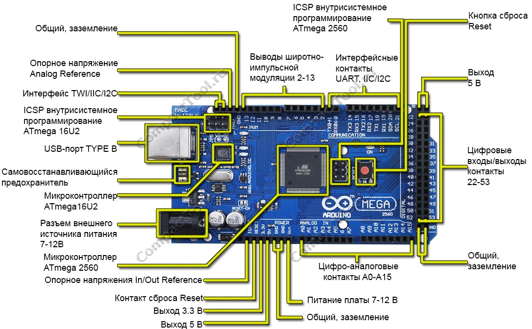
Next Sketch - Include Library (Add library) - at the very bottom we see u8glib appeared, select it.
A line appeared in our sketch:
#include Starting the firmware configuration:
1. You need to select the controller of our printer, for this we go to the boards.h tab
We see there a huge list of controllers with which the Marlin firmware can already work:
Let me remind you that we use Arduino Mega 2560 + RAMPS v 1.4 and we have a heating table, controlled blowing of the part and one print head. I think everyone has already found our board:
#define BOARD_RAMPS_14_EFB 43 // RAMPS 1.4 (Power outputs: Hotend, Fan, Bed)
Return to the Configuration.h tab line:
2. Setting the table temperature sensor.
Most likely you, just like I have a regular Chinese 100K thermistor, in this firmware it is denoted by the number 1:
// 1 is 100k thermistor - best choice for EPCOS 100k (4. 7k pullup) hotend and for the table:
We can leave the maximum and minimum temperatures unchanged or adjust to our needs:
3. PID settings - I recommend doing it after you have already printed on your printer for several hours.
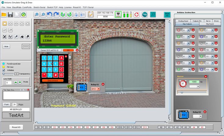
This is done as follows, in the Pronterface program, you need to connect to the printer
and give the command
Where M303 is the calibration command, E0 is the hot end, C10 is the number of heating-cooling cycles, S260 is the typical temperature of the nozzle.
The printer runs the hotend heating 10 times, after that it outputs the values Kp, Ki, Kd. We write these values into these firmware:
The same for the table, only the command:
M303 E-1 C10 S110
Where E-1 is the table, S110 is the typical table heating temperature.
Due to prolonged table heating, a timeout error may occur, just restart the command.
We enter the obtained values into the firmware:
4. Set up the operation of the limit switches:
Let me remind you that in our case we use: //)/uncomment the corresponding lines:
And also change the direction of the location of the 'house' in accordance with the position of the trailers:
4. Print field size settings.
In my case, it turned out exactly 200*200*190 mm:
Your values may differ slightly, literally mm, but this is established empirically later.
5. Setting the speed of moving home:
Set empirically, while leaving the default.
6. Setting the movement steps along the axes.
We need to find out how many steps our printer takes per unit of distance (in our case 1 mm) along each of the axes.
In our case, we use a motor that takes 200 steps per revolution, and we break this step into 16 microsteps.
Further along the X and Y axes we have a belt drive with a pitch of 2 mm for each tooth and a spool has 20 teeth.
Thus, our engine makes 200 * 16 = 3200 steps in one revolution and overcomes the distance 20 * 2 = 40 mm in these 3200 steps.
Therefore, in order for the printer to move 1 mm, it takes 3200/40 = 80 steps (this value is the same for the X axis and the Y axis).
A trapezoidal screw is installed on the Z axis, which has a different pitch, who purchased which one. For example, 8 mm per full turn, i.e. our printer travels 8 mm in one turn of the screw along the Z axis and does the same 3,200 for this, although to accelerate the Z axis, you can set crushing (with jumpers) and 1/8, how to do this is written in 3 parts.
So, on the Z axis, in order to move 1 mm, the printer needs to make 3200/8 = 400 steps.
Extruder feed. In order to understand how much our extruder feeds plastic, we need to calculate the circumference, from the school geometry course, remember that the circumference is 2 * 'number pi' * radius of the circle or 'number pi' * diameter of the circle. Now we don’t need special accuracy (we will adjust it more precisely later), the diameter is approximately 5.8 mm, therefore, in 3200 steps or one revolution, our extruder delivers 3.1415 * 5.8 = 18.2207 mm of the bar, and for the feed of one mm he needs 3,200 / 18.2207 = 175.624 steps, rounding up to the whole step 176.
We write the obtained values into the firmware:
Here, in order, X, Y, Z, extruder.
7. Setting speeds and accelerations:
leave these parameters unchanged for now and will adjust them in a more precise setting:
8. Setting the screen:
Uncomment (remove the double slash //) from the lines
#define ULTRA_LCD
#define DOGLCD
#define SDSUPPORT
#define ULTIPANEL
#define REPRAP_DISCOUNT_FULL_GRAPHIC_SMART_CONTROLLER
9. You can name your printer after yourself, for example 'Plastmaska'
To do this, uncomment the line:
//#define CUSTOM_MACHINE_NAME 'Plastmaska'
All basic firmware settings are done, check by pressing the 'Check' button :
And download by pressing the 'Load' button:
After that, our printer will reboot and show you various parameters.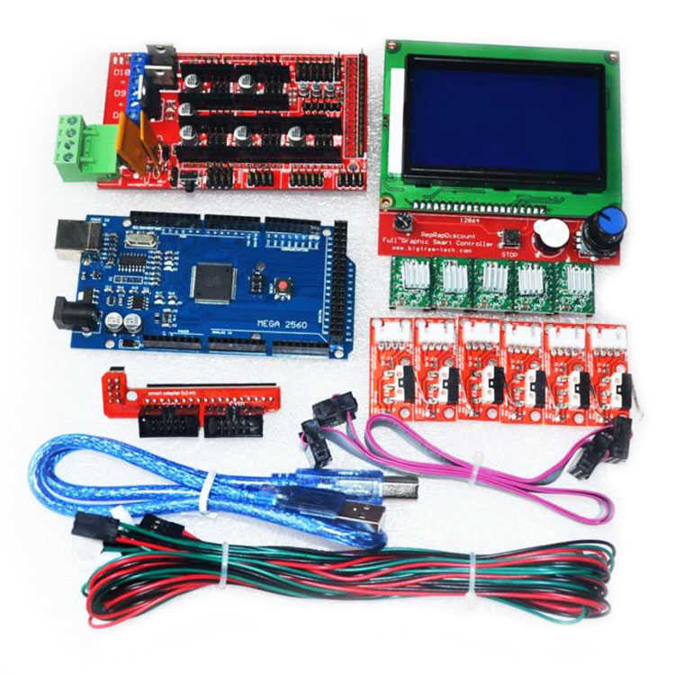
Now we need to fine-tune the printer:
1. the correct direction of movement along the axes.
Should be:
X-axis - left 0 (or minus), right 200 (or plus)
Y-axis - towards you 0 (or minus), away from you 200 (or plus)
Z-axis - up 0 (or minus), down 190 (or plus)
extruder - feeds plastic is plus, rolls plastic is minus
If everything matches, move on, if not, then change the parameters, change the parameter true to false or false to true - parameter changes only where it is needed (where movement along the axis is incorrect):
#define INVERT_X_DIR false
#define INVERT_Y_DIR true
#define INVERT_Z_DIR false
#define INVERT_E0_DIR false
compile and re-upload the firmware, check, match.
2. Limit switches operation:
Place the carriage and the table in such a way that the limit switches are not pressed.
Command M119 via the Pronterface program.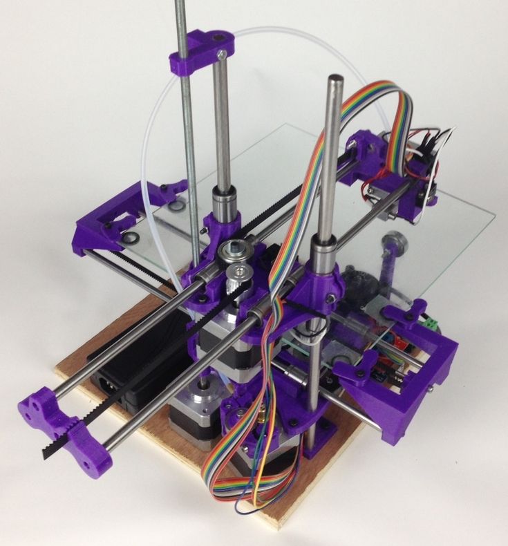
We see something like this:
or so
should be correct:
or
x_min: open
y_max: open
z_max: open
This is only for normally closed contacts, if you use normally open, then you should have the opposite, the limit switch did not work - open, the limit switch worked - TRIGGERED.
If something is wrong here, then most likely they made a mistake in the previous setting of the limit switches or in their connection. go back and check.
3. Proper travel home.
We give a command to the printer to go home, it is possible through the printer menu, it is possible through programs on the computer.
The carriage should move to the left and away from you, the table should move down.
Is everything correct? moving on. Not? we return to the firmware
4. We select the dimensions of the movement:
here everything is empirically and with a ruler we select the parameters for all axes and enter them into the firmware:
5. Checking the bar feed:
We take a line, measure 10-20-30 cm bar, mark and give the printer a command to squeeze out 10-20-30 cm of the bar, check how accurately he did it, based on the values we correct the firmware.
6. Selection of speeds and accelerations:
No one will tell you better than Sergey Taranenko:
We enter the obtained parameters into the firmware, fill it in the printer, check it.
7. Setting the gap between table and nozzle.
The table must first be covered with a coating for good adhesion to the table, I personally use a glue stick (3M Scotch, UHU, Kalyaka-Malyaka). I put glue on cold, clean, dry glass, after that you can heat the table, one of these days I plan to try glass-ceramic glass, nothing works from a pencil that has been tested better.
We heat up the table and the nozzle to the operating temperature (110/250) send the table to point 0, then along three points (where we have the adjusting screws)
Adjust the distance with nuts so that a sheet of paper is pressed between the nozzle and the table nozzle to the table, but at the same time it could be pulled out without tearing, it is necessary to achieve this so that there is such a distance at any point of the printer, for this it is enough to align the table 2 times at 3 points.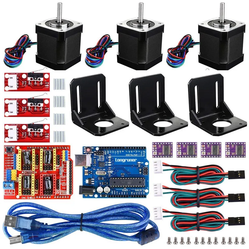
Some of the parameters can be changed via EEPROM, this can be done either in the Repetier-Host 9 program0003
Or using commands in the same Pronterface.
That's all, I'm waiting for your questions, on the basis of which I want to make a certain FAQ on the printer.
Also the last chapter '5. Firmware and printer setup - Repetier-Firmware.' is postponed indefinitely, because the printer on which it was planned to install this firmware suddenly received MKS Sbase, and that's another story.
Finally, another video of how the printer prints:
and this is what happened:
Another well-known model, but of higher quality and better material:
Well, the new owners of the printer are happy.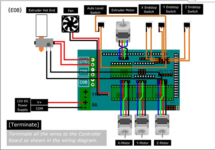
Examined:
Adhesive coating applied:
We set to work:
What I plan to do next, the first thing is to complete the project with a double-headed printer:
But in the near future I want to make a plywood Ultimaker Go, I really liked the idea of wearing takeaway:
It is possible that Repetier-Firmware sells there.
I also think in the direction of mixing colors when printing, in order to achieve this, but not with a gradient bar, but by mixing colors when printing:
How interested you were to follow these projects, please unsubscribe in the comments.
Update
Part 5. Updates and additions. >> http://3dtoday.ru/blogs/plastmaska/small-update-ultimaker/ Please support this project in social networks.