Apm 3d level scanner
APM 3D - Level - 3D Level Scanner by Echo Process ...
APM 3D - Level - 3D Level Scanner by Echo Process ...- Home breadcrumb
- Companies
- Echo Process Instrumentation, Inc.
- Products
- Model APM 3D - 3D Level Scanner
From Level
0
Share Share with Facebook Share with Tweeter Share with LinkedIn
The 3D Level Scanner - Model S determines the average volume of bulk solids stored in small silos with diameters up to 4 or 5 meters (13 - 16 feet) and height up to 70 meters (230 feet).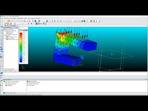 The 3D Level Scanner - Model M maps the entire surface area of practically any kind of bulk solids stored in large silos, open bins and stockpiles (up to 15 meters / 49 feet in diameter and heights of up to 70 meters / 230 feet), and generates highly accurate measurements of the level and volume of the contents.
The 3D Level Scanner - Model MV maps the entire surface area of practically any kind of bulk solids stored in large silos, open bins and stockpiles(up to 15 meters / 49 feet in diameter and heights of up to 70 meters / 230 feet), and generates highly accurate measures of the level and volume of the contents.
All models incorporate APM's proprietary non-contact dust-penetrating technology enabling it to overcome the challenges of harsh, dusty environments regardless of the type or characteristics of the material being stored. APM software provides a3D representation of the contents- including material build-up and other irregularities that form over time - for display on remote screens to facilitate timely intervention and maintenance.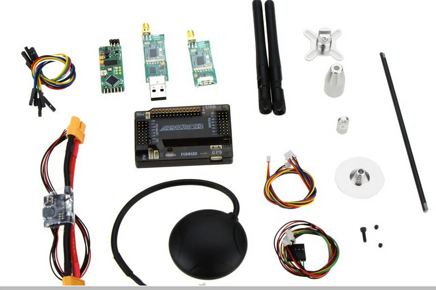
- Real Level Measurement
- Non-Contact Dust Penetrating
- Patented Self-Cleaning Technology
- Works With Any Dielectric Constant
- LCD Wizard Configuration
- Housing & Antenna: Painted Aluminum die cast
- Ambient, Storage, transport and process temperature: -40...85ºC (-104...185ºF)
- Vessel pressure: 0.2...3 bar (-2.9...43.5 PSI)
- LCD: 4 lines x 20 characters
- Adjustment elements: 4 keys
- Supply Voltage: 18...32 VDC
- Power Consumption: max 1.5W @ 24VDC
- Protection: IP67 according to IEC 60529
- Measuring Range: 70m (230ft)
- Beam Angle: 15 degrees
- Frequency: 4.5 KHz
- Reaction/Setting Time: < 5 s (dependent on the parameter adjustment)
3DLevelScanner S / M / MV - APM Automation Solutions Ltd.
 - PDF Catalogs | Technical Documentation
 Add to favorites
{{requestButtons}}
Catalog excerpts
3DLevelScanner 3DLevelScanner Changing the market from level to volume True Process Level and Volume Measurements of Bulk Solids APM’s 3DLevelScanner incorporates advanced technology for accurately measuring bulk solids and powders stored in silos and open bins of all types, shapes and sizes allowing production managers to make informed decisions about inventory control and usage. 1
APM Technology and the 3DLevelScanner The APM 3DLevelScanner is the only device presently available that delivers accurate measurement of bulk solids and powders regardless of the type of material or product characteristics, type and size of storage silo, bin or container, and harshness of the storage environment. It incorporates APM’s unique dust-penetrating technology to achieve an unrivaled degree of process measurement and inventory control. 3DLevelScanner Visualization Print Screen APM Automation Solutions Ltd. is a leading manufacturer and expert in level and volume measurement...
3DLevelScanner The 3DLevelScanner product line currently includes three models: Model S Determines the average volume of the stored contents. Based on a 30-degree beam angle, Model S is ideal for small silos up to 4 meters in diameter, and for tall (up to 70 meters) and narrow silos. Model M Yields highly accurate readings of level and volume. It is appropriate for large silos. It is based on a 70-degree beam angle. Model MV Identical to Model M, with the addition of a special software tool that allows 3D representation of the stored contents for display on a remote computer screen. This...
APM’s advanced technology beats the competition – hands-down It enables measurements of previously inaccessible applications. Seamlessly communicating with a plant’s existing ERP system, APM 3DLevelScanners give production managers greater control over inventories and the entire manufacturing process, optimizing the potential for greater overall efficiency and profitability. Comparison of APM Models and Competing Technologies 3DLevelScanner Competing Technologies Models Feature S MV • True volume measurement M • 3D surface visualization noncontact radar ultrasonic • • Reliable and accurate...
3DLevelScanner Accurate • Reliable • Robust • Safe The Vision of 3D Level Measurement Feature Benefit Multiple-point accuracy Taking measurements from multiple points rather than only a single point takes into account variations that occur on material surfaces Dust-penetrating, acoustic-based low-frequency technology Measurements are unaffected or distorted by dust, yielding accurate results where ultrasonic and radar have failed Non-contact measurement Appropriate for foods, chemicals and pharmaceuticals because there is no risk of contamination due to moving parts Unaffected by material...
Volume Error (%) APM - Changing The Market From Level To Volume 25 20 15 10 5 0 0 5 10 15 20 25 30 35 40 Silo Width (m) Single point level device Volume Accuracy APM 3DLevelScanner 3DLevelScanner M 3DLevelScanner MV 3DLevelScanner S Contact Guided Radar Capacitive Ultrasonic Non-contact radar Application Spectrum *Application Spectrum - application range in silos, open bins, warehouses and stockpiles under harsh conditions (dust, moisture, etc. ) 6 * APM 3DLevelScanner offers uncompromising win-win strategies for both technical and business managers: day-in, dayout it provides accurate...
3DLevelScanner APM Gets It Right Safety Steel grain bins have been susceptible to collapse, resulting in catastrophic failures attributed to uneven sidewall loading. This can be caused by hanging grain from spoilage or asymmetric filling and emptying. The 3DLevelScanner MV provides early visual detection of all such conditions long before they threaten the structural integrity of the container. This enables the production manager to intervene with appropriate maintenance, avoiding costly damage or loss of storage facilities as well as unexpected interruptions of production. Operational...
3DLevelScanner APM - Get Accurate GSM/GPRS APM Automation Solutions Ltd. www.apm-solutions.com | [email protected] © 2012 APM Automation Solutions Ltd. All rights reserved. Information in this document is subject to change without notice. APM Automation Solutions Ltd. and the APM Logo, are trademarks, and the 3DLevelScanner is a registered trademark of APM Automation Solutions Ltd. BRO0000100 Rev 2 4…20 mA/HART RS485/Modbus/TCP/IP
All APM Automation Solutions Ltd. catalogs and technical brochures
-
3D MultiVision Software
4 Pages
-
Volcan White Paper
5 Pages
-
3DLevelManager
52 Pages
-
3DLevelScanner HC
4 Pages
-
3D MultiVision Mobile Application
2 Pages
-
3DLevelScanner HT
4 Pages
-
MultiScanner System (MVL) Brochure
8 Pages
-
3DLevelScanner Technical Data Sheet
8 Pages
-
3DLinkPro - wireless GSM communication with your 3DLevelScanner
6 Pages
Compare
Remove all
Compare up to 10 products
3D laser scanner on Android phone / Habr
I present to your attention a DIY scanner based on an Android smartphone.
When designing and creating a scanner, first of all, we were interested in scanning large objects. At least - a full-length figure of a person with an accuracy of at least 1-2 mm.
These criteria have been successfully achieved. Objects are successfully scanned in natural light (without direct sunlight). The scanning field is determined by the capture angle of the smartphone camera and the distance at which the laser beam remains bright enough for detection (during the day indoors). This is a full-length human figure (1.8 meters) with a grip width of 1.2 meters. nine0003
The scanner was made for reasons of "whether to do something more or less useful and interesting when there is nothing to do." All illustrations are based on the example of a “test” object (it is not correct to post scans of people).
As experience has shown, for a scanner of this type, software is secondary and the least time was spent on it (on the final version. Not counting experiments and dead ends). Therefore, in the article I will not touch on the features of the software (Link to source codes at the end of the article.)
The purpose of this article is to talk about dead ends and issues collected along the way to creating a final working version.
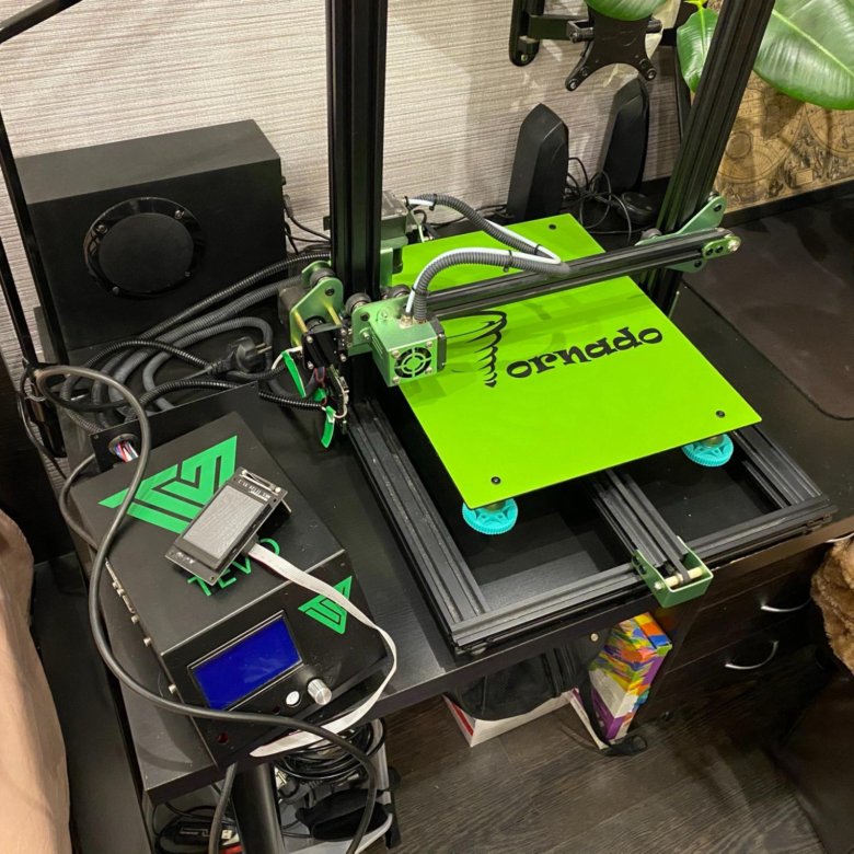
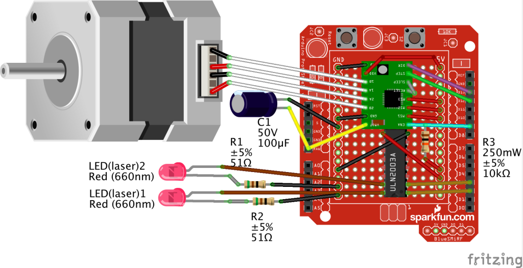
For the scanner in the final version is used:
- Samsung S5 phone
- 30mW red and green lasers with line lens (90 degree line) with glass optics (not the cheapest).
- Stepper motors 35BYGHM302-06LA 0.3A, 0.9°
- Stepper motor drivers A4988 nine0017 Bluetooth module HC-05
- STM32F103C8t board
The A4988 drivers are set to half step, which with a 15->120 reducer gives 400*2*8 steps per PI.
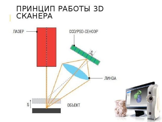
Select the scanning technology.
The following different options were considered.
LED Projector.
The option was considered and calculated. Even expensive projectors do not have the required resolution to achieve the required accuracy. And it makes no sense to even talk about cheap ones. nine0003
Mechanical sweep of the laser beam in combination with a diffraction grating.
The idea was tested and found to be suitable. But not for DIY performance, for reasons:
- A sufficiently powerful laser is needed so that after diffraction the marks are bright enough (the distance to the smartphone lens is 1..2 meters). And the eyes are pitiful. A laser point already with 30mW is not useful.
- 2D mechanical reamer accuracy requirements too high for DIY. nine0018
Standard mechanical scanning of the laser line on a stationary scanned object.
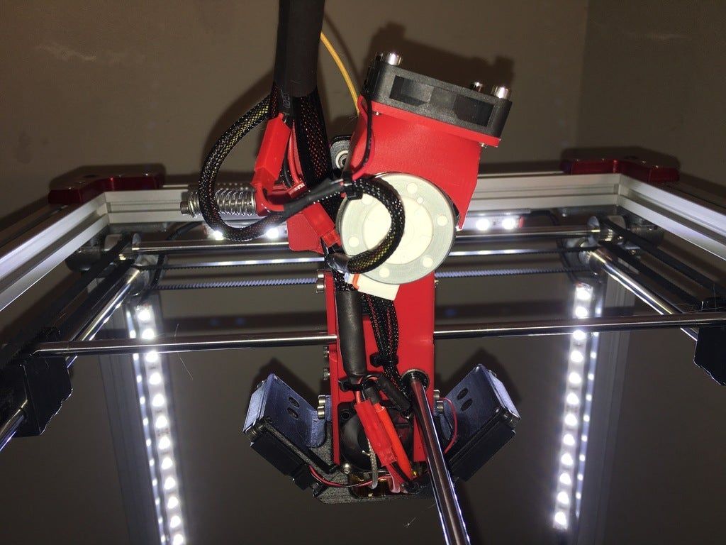
In the end, the option with two lasers of different colors was chosen
- Different colors of lasers make it possible to independently detect them in one frame.
- The location of the lasers on different sides of the camera allows you to get two scans in one pass.
- Two scans at a time allows you to objectively assess the quality of the scanner alignment (scans should converge and overlap each other). nine0018
As it turned out, the last criterion is the most important. The quality of the scan is entirely determined by the accuracy of measuring the geometric dimensions and angles of the scanner. And the presence of two scans from two lasers allows you to immediately evaluate the quality of the scan:
The point clouds converged. Those. the planes captured by the two lasers converged over the entire surface.
Although from the very beginning I assumed that this was a dead end version that did not provide the necessary accuracy, I still tested it with various tricks:0003
- The motor shaft is fixed with a bearing.
- Added a friction element and a stopper for reducing gear backlash.
- Attempt to determine the "exact position" by a phototransistor, by laser illumination
The repeatability of returning to the same place of the laser line was low - 2-3 mm at a distance of 1.5 meters. During the operation of the gearbox, despite the apparent smoothness, jerks of 1-3 mm are noticeable at a distance of 1.5 meters.
i.e. 28BYJ-48 is completely unsuitable for a more or less accurate large object scanner. nine0003
Reamer requirements based on my experience
Reamer must be a mandatory element.
Make no mistake about the 1/x step mode. Experiments have shown that in 1/16 mode on the A4988 the micro steps are not uniform. And at 1/8 this unevenness is noticeable to the eye.
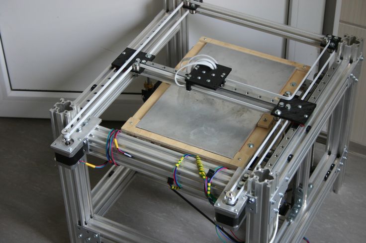
The best solution for the gearbox was the use of a belt gear. Although it turned out to be quite cumbersome, it is easy to create and accurate.
The positioning accuracy (more precisely, the repeatability of the positioning of the initial position of the lasers for scanning) of the lasers turned out to be about 0. 5 mm for a 5 mm laser line width at a distance of 4 meters. Those. at a scanning distance (1.2-1.8 meters) it is generally difficult to measure. nine0003
Positioning - optocouplers (Chinese noname) on a slot in the disk under the lasers.
Problems with the transmission of control signals from the phone to the laser and stepper motor control module
The bottleneck in terms of scanning speed was the control channel. Since this was a DIY leisurely development for my own pleasure, we tried all the ways to communicate with a smartphone.
Transmission of control signals via Audio jack (phone Audio jack=> oscilloscope)
The slowest way to transfer data in real time. Yes, even with floating time. Up to 500 ms (!) from software activation of audio data transfer to the actual appearance of a signal in the Audio jack.
This exotic was tested because, at work, I had to deal with mobile chip card readers.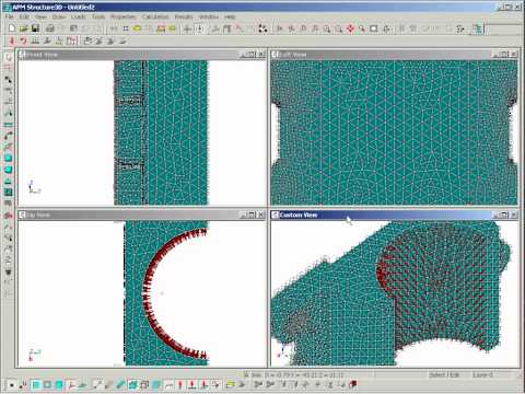
Photodiodes on the smartphone screen (a piece of the phone screen => phototransistors + STM32F103)
For the sake of interest, even such an exotic method was tested as phototransistors with a 2x2 matrix in the form of a clothespin on the screen. nine0003
Although this method of issuing information from the phone turned out to be the fastest, it is not so fundamentally faster (10 ms vs 50ms) than Bluetooth to put up with its shortcomings (a clothespin on the screen).
IR channel (phone=>TSOP1736->STM32F103)
The method of transmission through the IR channel has also been practically tested. Even some implementation of the data transfer protocol had to be done.
But IR also turned out to be not very convenient (it is inconvenient to mount a photo sensor on a phone), and not too faster than Bluetooth. nine0003
WiFi module (phone=>ESP8266-RS232->STM32F103)
The results of testing this module were completely discouraging. The request-response execution time (echo) turned out to be unpredictably floating in the range of 20-300 ms (average 150 ms). Why and what - did not understand. I just came across an article that talked about an unsuccessful attempt to use the ESP8266 for real-time data exchange with strict request / response time requirements.
i.e. ESP8266 with "standard" firmware TCP -> RS232 is not suitable for such purposes. nine0003
Selected control unit and signal transmission
Ultimately, after all the experiments, the Bluetooth (HC-05 module) channel was chosen. Gives a stable (and this is the most important) data transfer request-response time of 40ms.
The time is quite large and greatly affects the scan time (half of the total time).
But the best option was not achieved.
Widespread board with SM32F103C8T as control module. nine0003
Line detection methods on a frame.
The easiest way to highlight the laser lines on the frame is to use the subtraction of the frame with the laser off and the frame with the laser.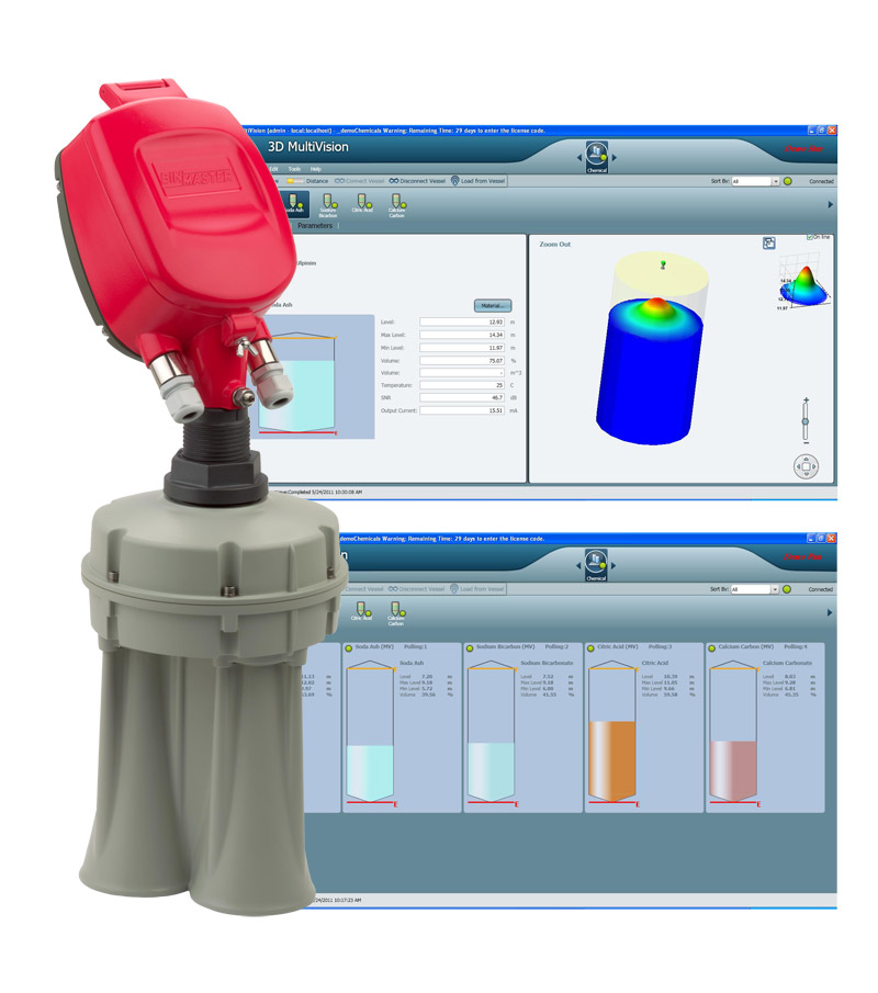
In principle, search by frame without subtraction also works. But it works much worse in daylight. Although this mode was left in the software for the sake of comparative tests (the photo of the mode is below. All other photos with the frame subtraction mode).
The practical value of the variant without frame subtraction turned out to be low. nine0003
It is possible and possible to extract the laser signal from this noisy information. However, he did not bother.
Frame subtraction works well.
All sorts of experiments with attempts to approximate the line and processing the entire frame have shown that the more complex the algorithm, the more often it "mistakes" and even slows down the processing "on the fly". The fastest (and simplest) algorithm was found to search for a laser (laser point) on a horizontal line:
- For each line point, the sum of the squares of the laser color level (RGB) in the window specified in the configuration (13 px is the experimentally optimal value for the window) is calculated nine0018
- Laser point - the middle of the window with the maximum value of sums of "color" levels.
The time for processing one frame by searching for the "green" and "red lines" is 3ms.
Point clouds for red and green laser are counted separately. With correct mechanical alignment, they converge with an accuracy of < 1 mm.
Accuracy and adjustment
The accuracy was within 1 mm at a distance of 1.2 meters. Mostly due to the resolution of the phone's camera (1920x1080) and laser beam width.
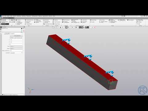
It is very important to make static and dynamic adjustments to obtain correct scans. The accuracy / inaccuracy of the settings is clearly visible when both point clouds are loaded into MeshLab. Ideally, the point clouds should converge, complementing each other.
Static parameters, set as accurately as possible once:
- Tangent of the camera's field of view.
- The length of the "shoulders" of lasers (from the center of the lens to the axis of rotation).
 nine0029
 -
Software and regular updates
-
Online support
-
Blue-Light Technology
-
Industrial Precision
-
Excellent value for money
- Registered measuring instrument
- Reverse engineering
- Measurements and quality control nine0018
- Detailed visualization
- Small size
- The average size
- Big size
-
Scanning on a turntable
Quickly and easily scan an object mounted on a turntable platform with the push of a button.
 When the object is rotated, the fragments of the model are aligned automatically.
 Read more
-
Scanning with markers
Automatic alignment of model fragments by markers applied to the surface of the object. Used to improve the accuracy of stitching large objects. External photogrammetry systems are supported. nine0003
Read more
-
Basic Scan
Used to scan objects that cannot be digitized in other ways, such as museum exhibits. The fragments of the model obtained from different angles are combined according to the features of the object surface geometry.
Read more
-
License key
If the main license key is lost or damaged, a new license can be generated for your scanner and an additional key issued.
 The previous license is then blocked.
 Buy
-
Protective case
The RangeVision PRO 3D scanner comes in a special plastic box with a lodgment for easy transportation and storage of the scanner. If you want to have additional guaranteed protection against impacts during transportation, instead of a standard box, the 3D scanner can be supplied in a special protective case. Depending on the configuration, the tripod and turntable can be supplied separately.
Buy
- nine0303 Turntable TL
The turntable allows you to automate the process of scanning small objects. The table platform rotates 360° through a predetermined angle, allowing you to scan an object from different angles and automatically combine scans. The turntable is connected to the control computer via a USB port, and to a 220V network via a power adapter.
Load capacity 60 kg Diameter 32 cm
Buy
nine0017 -
PC
Control PC not included with RangeVision PRO 3D Scanner. It can be purchased separately if desired.
Buy
nine0151 -
Pinion View on site
-
Bracket
-
Disc View on site
nine0018 -
Screw View on site
-
Game miniature View on site
-
Baseball View on site
nine0018 -
Cork View on site
-
Car door handle View on site
-
Eastern imperial eagle skeleton.
 Made by the Museum of Fine Arts in Budapest, Hungary. Solution Provider: 3D Parade 3dparade.com. View on site nine0003
 -
Chair leg View on site
-
Skull View on site
-
SsangYong Rexton
And of course, the maximum focusing of the laser lenses at a given scanning distance and the “verticality” of the laser lines.
The dynamic parameter of the actual position angle of the lasers relative to the virtual plane of the frame has to be re-adjusted every time the phone is mixed in the mount. To do this, the setup mode in the software is made. By bringing the lasers to the center of the screen and adjusting the angle, it is necessary to set the calculated distance as close as possible to the true (measured) distance for both lasers. nine0003
Before adjustment:
After adjustment:
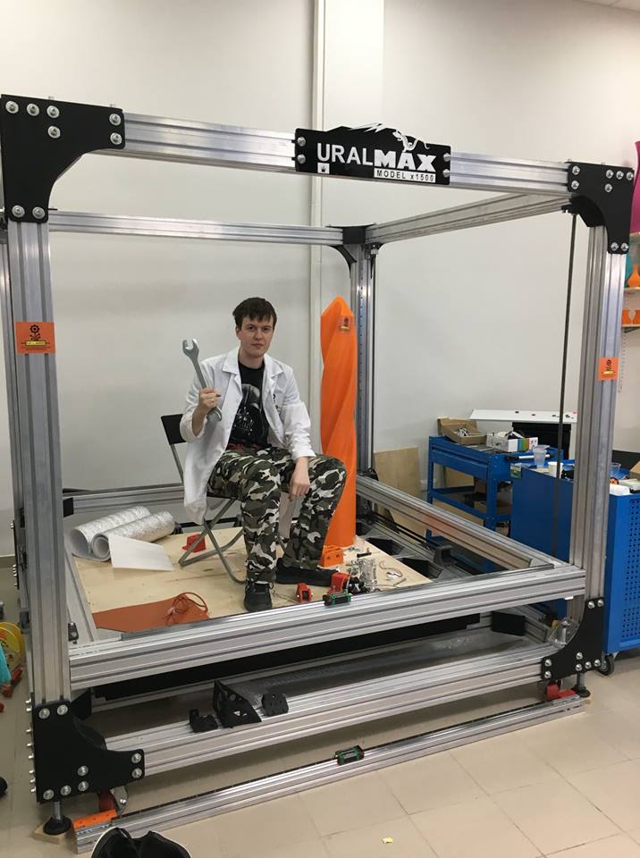
Pins
Such a design, perhaps, can be repeated by anyone. I cut out all the details from fiberglass on the CNC.
Of course, without a CNC router, it is difficult to make a pulley for a laser. But taking into account the fact that you need a maximum angle of rotation of 90 degrees, then with due patience, the pulley can also be cut with a needle file.
But it is still better to do it on the CNC. The requirements for axial clearance of the swivel assembly are high. The quality of scans is 100% determined by the accuracy of manufacturing and alignment. nine0003
The scanner was doing it in the background. Sometimes with breaks for a couple of months. Therefore, I cannot estimate the total complexity of its creation.
The overall construction cost is not too high. As my experiments have shown, although it is far from industrial scanners for large objects, you can get quite decent scans.
The quality of the scans is primarily affected by the accuracy of the mechanical part. In this sense, in DIY, it is difficult to deal with the mechanics created for industrial scanners. nine0003
Source Code
RangeVision PRO
RangeVision PRO You have disabled JavaScript. It scares.Partners
Industrial solution,
available to any size company
Get accurate 3D models for your production
Sign up for a free online demo!
Get a unique opportunity to test the RangeVision PRO 3D scanner online before choosing. Convince yourself of its capabilities!
RangeVision PRO - scanning objects from jeweler size to car scale
Variable scan areas
Applications
Excellent value for money
RangeVision 3D scanner delivers excellent performance at a price significantly lower than systems with
comparable features. Get an affordable price for a professional solution that meets your needs
Three by 3
For convenient work with different types of objects
Choose the right mode for your tasks
Fully equipped with everything you need
Standard scope of supply includes:
Additional options
Calibration fields
A set of additional calibration fields for working with different scanning areas.
Buy
10 questions before buying a 3D scanner
3D model examples
Specifications
| Scan Technology | structured illumination | ||
| Projector resolution | 1920 x 1080 | ||
| Scan area, mm nine0003 | 550x340x360 | 320x210x200 | 140x90x80 |
| Working distance, m | 0. | 0.52 | nine0412 |
| Error, µm | 60 | thirty | eighteen |
| 3D resolution, mm | 0.18 nine0003 | 0.10 | 0.04 |
| Ability to capture texture | eat | ||
| Camera resolution | 6.4 MP nine0003 | ||
| Model stitching | by markers, by geometry | ||
| Received formats | OBJ, PLY, STL, PTX, ASCII | ||
| Scanner Power | nine0416 |||
| Connection interface | HDMI, 2x USB 3.0 USB 2. | ||
| Supported OS | Windows 8.1/10/11 64bit | nine0420 ||
| Rotary table | eat | ||
| Table platform diameter | 32 cm | ||
| Maximum table load | 60 kg nine0003 | ||
| Dimensions of the scanner in the case | 620x420x460 | ||
| Scanner weight | 6.5 kg | ||
| Weight of the scanner in the case | 17.5 kg nine0003 | ||
| Certificates | EAC | ||
| Guarantee | 1 year | ||
 9
9  0 for desk
 Note: Product appearance may differ from website photos.