5 axis 3d printer slicer
5 Axis Slicer – Dotx Control Solutions
The first true multi-axis slicing software
The 5 Axis Slicer is a slicer tailoired specifically for additive manufacturing machines having 5 or more axis. The slicing process works the same as any other ‘normal’ slicer except that the layer generation allows for curved layers. This gives some unique opportunities such as printing without overhangs or printing on top of existing objects (using a welding robot, for example)
Examples of objects sliced with the 5 Axis Slicer
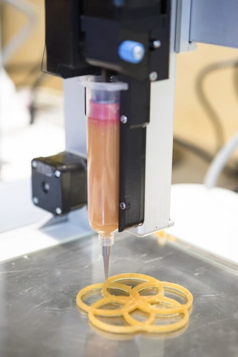
Example 1: A coil
The example of the coil shows how the toolpaths are calculated for a coil. The coil can be printed without overhangs, and without support structures.
Example 2: T-Shape
In the T-shaped object shown below we show that the automatic layer generation works even when there is multiple features in a part. Another slicing strategie would be to print the center piece first, and then print the T-pieces on the object.
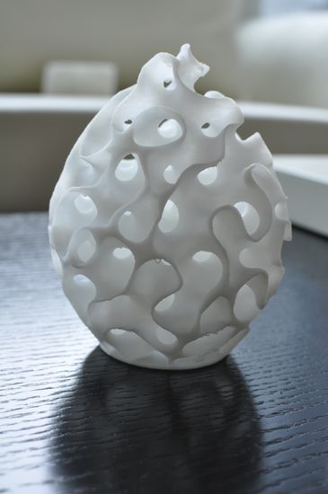
Example 3: An impeller
The example of the impeller shows how the 5 Axis Slicer can be used for practical prints. The curved layers make sure the blades are printed without any overhang.
Features
Slicing of complex 3D Models
The 5 Axis Slicer requires two .STL models to generate a toolpath. The first model is the print itself, while the second model is the ‘base’ layer, e.g. for a normal 3d-printer this would simply be a flat bed. In our case the ‘base’ can be anything as long as it is a suitable printing surface and an .stl is available for it.
Examples of a ‘base’ layer:
- A 3d-scanned car body panel
- A 3d-scanned face
Generate advanced infill
The infill generation algorithm is focused on adding strength to the object. The infill is laid down alternating per layer, creating the same type of infill used in normal (2D) slicers.
The infill has the following options:
- The orientation of the infill
- The density of the infill
- The overlap of the infill with the perimeters.
- Speed of the infill
- Temperature of the infill
- Material of the infill
Create a g-code for your machine
The 5 Axis Slicer generates G-Code in the absolute coordinate system, where the direction of the nozzle is defined by a normal vector. Using our g-code postprocessor the g-code can be expressed in the g-code required by your machine (e.g. a rotating bed, or a Kuka robot arm)
Create beautifull top layers
The 5 Axis Slicers makes sure that the toolpaths of solid (e.g. top/bottom layers) are perfectly aligned. To make sure the top layers are printed as good as possible we have the following options:
- Keep the speed of the printhead constant, despite rotations of the extruder.
- Ironing. The extruder does additional passes along the top layer, while no material is extruded. This ‘irons’ out any visible print lines.
Calibration of the surface to print on
The 5 Axis Slicer is designed to print on top of an excisting surface. Determining the exact location of this surface is done in a same way used in multi-axis CNC routers.
A touchoff procedure is designed by the slicer. A G-code is made in which the printhead moves to uniformly distributed points on the surface. The offset at which the printhead is located is measured, and entered in the 5 Axis Slicer. The 5 Axis Slicer than automatically takes into account translations, rotations, and even a possible scaling when creating the toolpaths.
Real world applications
The videos below show real world applications. The first shows how to go from design to print, where the object is finally printed with an industrial robot (in plastic).
What will you make?
The 5 Axis Slicer is not a slicer you will use or need on a consumer desktop printer. We focus on industrial machines where our software really gives additional value to your machine.
Therefore we would love to work with you, to:
- Make sure the slicer works for your specific machine.
- Add features that you would like to see for your machine.
Please note that we are currently focussing on professional users (not students). If you are professionally interested, please contact us through email.
5 Axis Slicer – The first true multi-axis slicing software
The first true multi-axis slicing software
The 5 Axis Slicer is tailoired to additive manufacturing machines with 5 or more axis.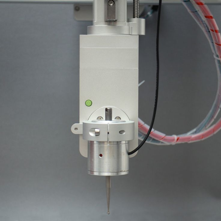 The slicing process works the same as any other ‘normal’ slicer except that the layer generation allows for curved layers. This gives some unique opportunities such as:
- printing with zero overhang (where every layer of material is printed on a ‘previous’ layer with 100% overlap)
- printing on top of existing (curved) objects
- printing without supports
For the above reasons, the 5-Axis Slicer is used for metal repair, printing plastics on metal parts, and printing complex objects (in metal and/or plastic).
Examples of objects sliced with the 5 Axis Slicer
Example 1: A coil
The example of the coil shows a simulation of the toolhead motions (the ‘stick’) and the layer deposition (in yellow). The layers are deposited with zero overhang, and therefore, this coil can be printed without support structures.
Example 2: Panton Chair
This example shows how the Panton Chair can be printed in any material (plastic or metal) with zero overhang and without support structures.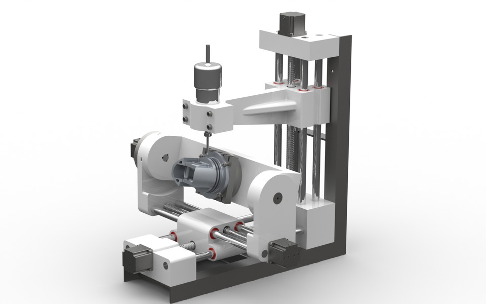 The nozzle is represented by the ‘stick’, while the deposited material is shown in yellow.
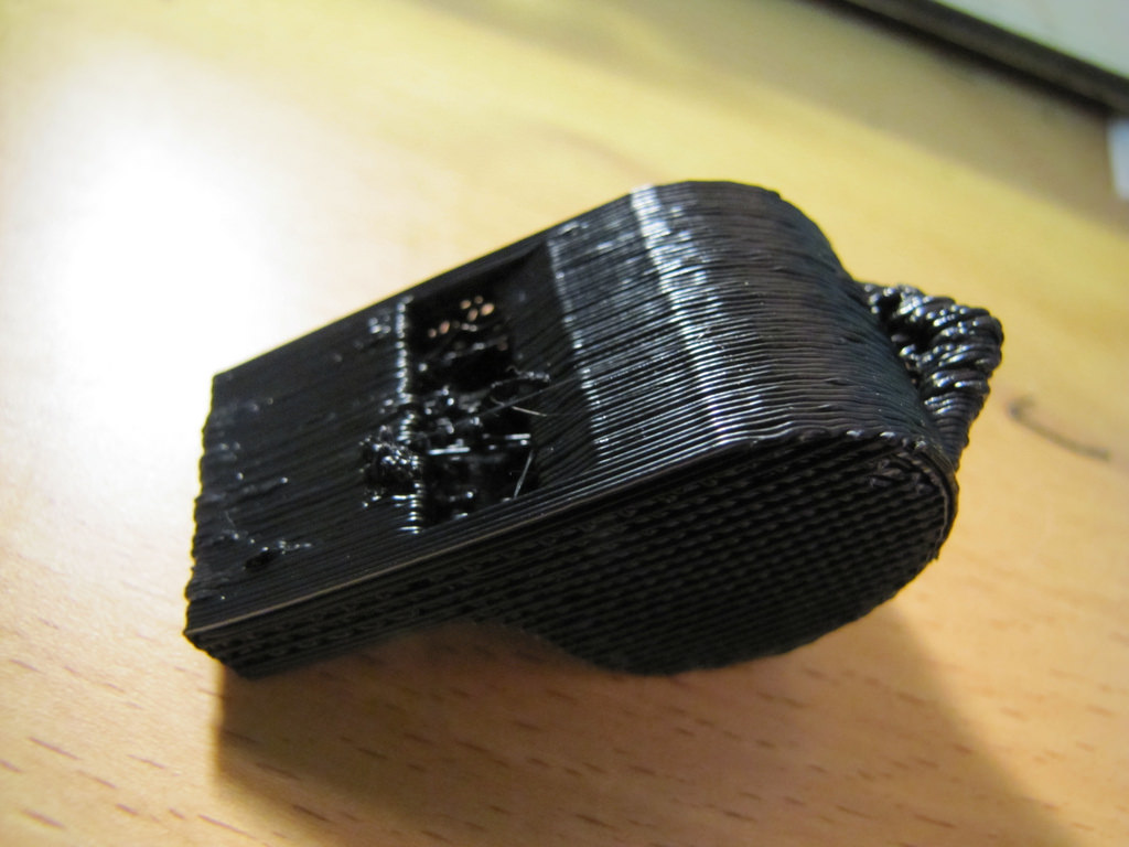
Example 3: Segmented toolpaths
The example shows how the 5 Axis Slicer can be used to generate toolpaths for segmented printing. This block can also be sliced in one piece, resulting in curved layers.
Example 4: Radial toolpaths
The 5 Axis Slicer can generate radial toolpaths as well, just by selecting a tubular base, allowing to print complex shapes with zero overhang and without supports.
Real world applications
The videos below show real world applications. The first shows how to go from design to print, where the object is finally printed with an industrial robot (in plastic). The second video shows how the 5-Axis Slicer is used in metal repair. The third video shows how it is used to print polymer on a metal car part. The last video (most right) shows how radial toolpaths can be generated. In all cases, there is no overhang and no supports are needed.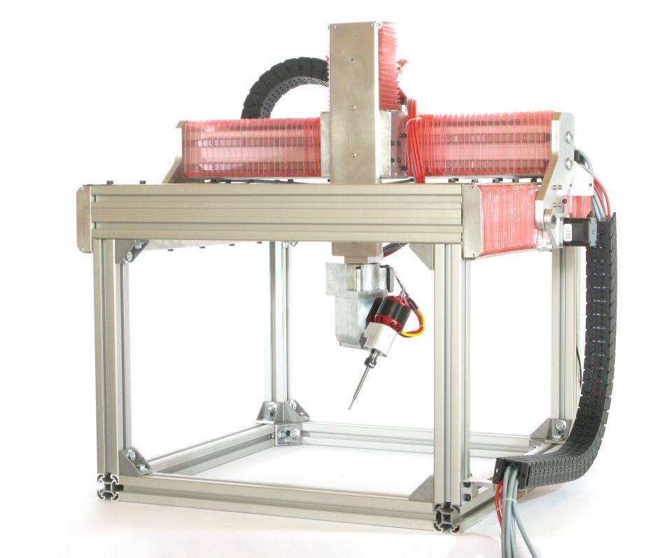
How it works
The 5 Axis Slicer requires two .STL models to generate a toolpath: a Print model and a Base model. The first model is the print itself. This should be a solid “waterttight” object with a realistic thickness. The Base model is the base on which you want to print.
Examples of a Base:
- a flat surface
- a 3d-scanned car body panel
- a segmented part of the object, printed previously
Simulate and create 3D printer commands
The 5-Axis Slicer allows you to simulate the printing process with any toolhead, by uploading a STL model of it. Once you are done, press the button for “Save gcode’, and use this file in your favourite postprocessor. For instance, use RoboDK, Robotmaster or Robotstudio to generate print comands (for both robot and print tool). For non robot printers, we can provide postprocessors (for instance for Duet control boards).
What will you make?
The 5 Axis Slicer is not a slicer you will use or need on a consumer desktop printer. It is meant for industrial multi-axis 3D printing machines.
Therefore, we would love to work with you, to:
- Make sure the slicer works for your specific machine.
- Add features that you would like to see for your machine.
- Provide a complete 3D printing station, including hardware and software
affordable 5-axis 3D printing and conformal printing
mike_vp
Loading
03/14/2022
7163
Miscellaneous
Subscribe to the author
Subscribe
I do not want
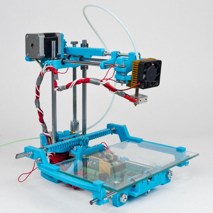
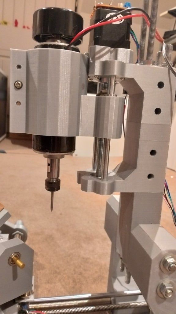
Freddy Hong, Steve Hodges, Konnor Myant, David Boyle based on the well -known PRUSA I3 MK3S Printer.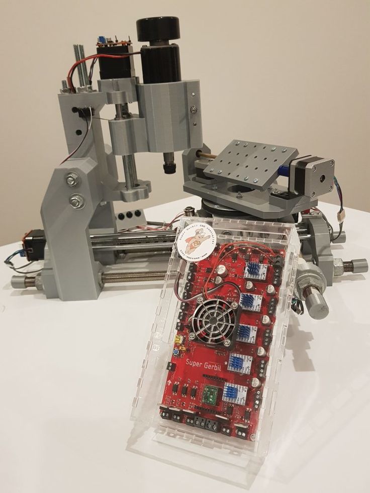 The authors want to present their work at the CHI 2022 conference.
As the creators themselves write: "We want 5-axis 3D printing to attract more hobbyists and manufacturers. The Prusa i3 MK3s was chosen as the base printer because it is perhaps the most popular/common hardware for desktop FDM 3D printers with a large community of users We also appreciate the openness of the Prusa i3 which has made the job much easier. a serial 3D printer can be upgraded to 5-axis 3D printing.0003
To make multi-axis 3D printing accessible to more manufacturers and researchers, we have developed a cheap and affordable way to upgrade a conventional 3D printer to a 5-axis one. We have also developed a conformal GUI slicer integrated into the popular CAD package. Together, they provide an accessible workflow for designing, modeling, and creating conformally printed 3D models."0003
The online repository (to be published on March 17) contains detailed information on all mechanical parts and 3D printing files needed to assemble the equipment.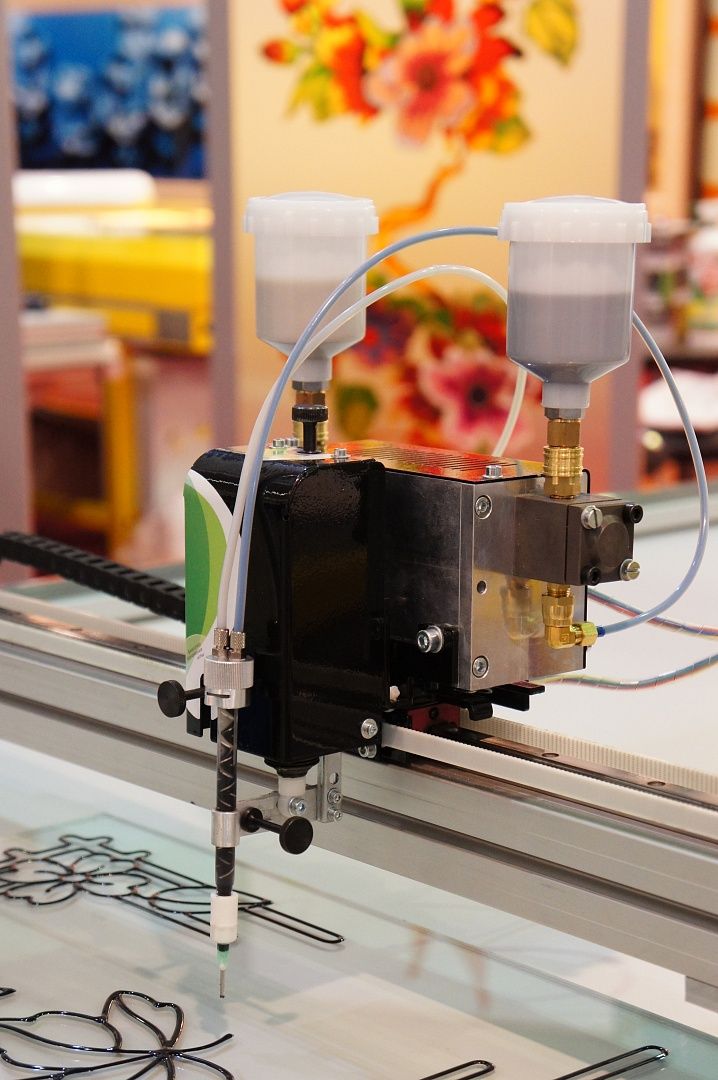 The repository will also contain development versions of the conformal slicer. (It would benefit a lot from more user contributions!)
prusa i3 5-AXIS 3D PRINTING
Follow author
Subscribe
Don't want
50
Article comments
More interesting articles
6
Subscribe to the author
Subscribe
Don't want to
The fog of war is thickening, the howling wind brings disturbing signs - it is time to prepare for battle...
Read more
one
Subscribe to the author
Subscribe
Don't want
Loading
07/16/2016
29025
129
Subscribe to the author
Subscribe
Don't want
Good afternoon!
There was a need to change the color on the desired layer during the printing process.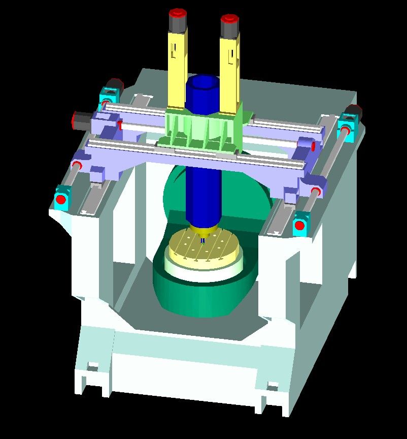 ...
...
Read more
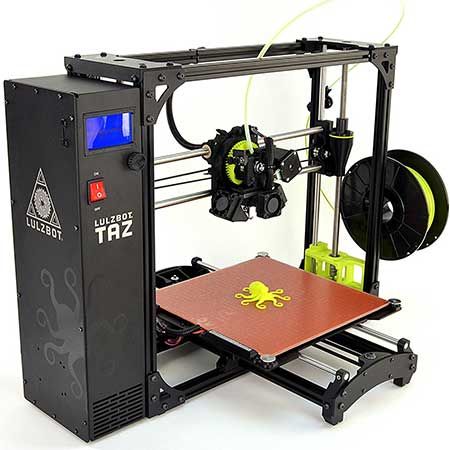
New 5 axis 3d printer from VERASHAPE
Pelevin N. 0 Comments 3d printing, Material, Equipment, Technologies
VERASHAPE has announced that its subsidiary VSHAPER is preparing to release a new 3d printer with five axes. This printer is named VSHAPER 5AX. The development of a 5-axis 3d printer in a subsidiary of VERASHAPE is a logical step, since VERASHAPE itself produces multi-axis CNC machines. The use of 5-axis technology for fusing 3D printing (FFF) allows the VSHAPER 5AX printer to stand out from other desktop 3d printers available on the market that mainly use the technology of robots working in a rectangular (Cartesian) coordinate system.
Why 5 axles?
Most desktop 3d printers usually use the Cartesian coordinate approach. Five-axis additive manufacturing is an attempt to get around some of the limitations that engineers face by using 3D printers to create objects from thermoplastic materials.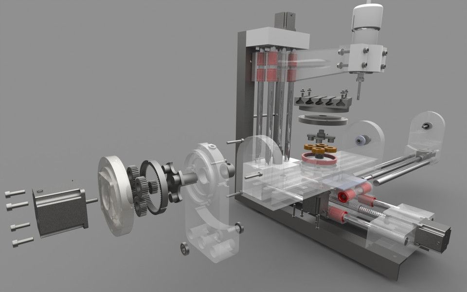
Part of this problem with traditional desktop 3D printers using FFF technology is to ensure uniform material strength after fusing. Engineers have to prototype objects or create custom components so that the uniformity of material properties such as strength is predictable and measurable.
According to VERASHAPE, in the case of traditional 3D printers, all the complexity comes from how the 3D model is placed on the fixed platform of the printer before the layering and layering process begins. The strength of the material in this case may be uneven, or differ from the expected. In addition, the layered technology increases the consumption of material, requiring a significant amount of it to form the supporting elements.
VSHAPER 5AX
The platform on which the object is formed in VSHAPER 5AX can rotate and tilt. This gives the user the ability to change the position of the 3d model, positioning the platform optimally in relation to the main planes, instead of changing the position of the printer's fusing heads relative to the fixed platform of traditional desktop 3d printers.