3D solids scanner
Rosemount 5708 Series 3D Solids Scanner | Level Transmitters
Skip to Main Content
Low frequency acoustic waves deliver accurate volume and level measurements of bulk solids and powders. Learn more...
Rosemount 5708 Series 3D Solids Scanner- Rosemount 5708 Series 3D Solids Scanner
- Rosemount 5708 Series 3D Solids Scanner
- Rosemount 5708 Series 3D Solids Scanner Basic Configuration Guide
- osemount 5708 Series 3D Solids Scanner Installation Guide
Retired products cannot be ordered
The Rosemount 5408 Radar Level Transmitter is the recommended replacement
View Company Reviews Trustpilot
Manufactured
- By Rosemount
Includes
- FREE Ground Shipping
- FREE Lifetime Tech Support
Product Manual Product Specs
Overview
Features
- Dead band is 19.
6in (0.5m) from top of antenna
- Up to 230ft (70m) measurement range
- Minimum bulk density of 12.5lb/ft3 (200kg/m3)
- Process fitting thread, angle adapter
- 2.3 to 7kHz emitting frequency
- Polyurethane covered aluminum housing material
- 4-20mA & RS-485 with Modbus signal output
Description
The Rosemount 5708 series 3D solids scanner uses a multiple point measurement technology to deliver accurate volume and level measurement of bulk solids and powders regardless of material type, product characteristics, storage silo type, size, or harshness of the storage environment. The 5708L, 5708V, and 5708S models enable efficient process measurement and true inventory management of bulk solid materials used in industrial applications including:
- Large open bins
- Bulk solid storage rooms
- Stockpiles and warehouses
- Loads that randomly form over time inside silos
The device includes an integral array of three antennas that generate unique dust-penetrating low frequency acoustic waves
and receive echoes from the contents.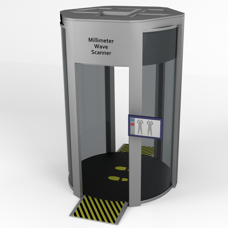 Using these antennas, the unit measures not only the time/distance of each echo, but also
its direction.
Using these antennas, the unit measures not only the time/distance of each echo, but also
its direction.
Collecting multiple echoes from different directions and distances enables the scanner to accurately calculate the volume of stored material. It also enables the 3DVision software to generate the 3D visualization of the material.
The acoustic waves combined with self-cleaning capabilities prevent material from adhering to the internal workings of the antenna array, ensuring long-term reliable performance with very low maintenance requirements, regardless of harsh dusty conditions.
Documents
Spec Sheets
- Rosemount 5708 Series 3D Solids Scanner Datasheet PDF (3.5 MB)
Manuals
-
Rosemount 5708 Series 3D Solids Scanner Manual PDF
(34.
 1 MB)
1 MB)
Other
- Rosemount 5708 Series 3D Solids Scanner Quick Start Guide PDF (25.6 MB)
- Instrumart's Level Application Form PDF (141 KB)
Accessories
Service Options
$2,294.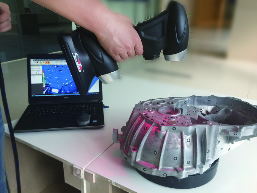 56
56
Starting at $4,800.00
Accessories
Please consider these optional accessories.
Starting at $2,740.96
Starting at $6,699.51
Starting at
$1,178.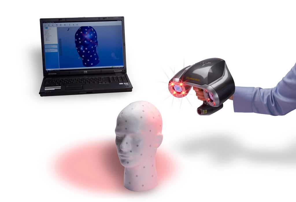 67
67
Need Help? Call a Calibration Engineer at 1-800-884-4967
We're open Mo-Th 8am to 5:30pm. Fr 8am to 5pm ET
Mark D.
Applications Engineer
11 years at Instrumart
Mike C.
Senior Applications Engineer
22 years at Instrumart
Angelo S.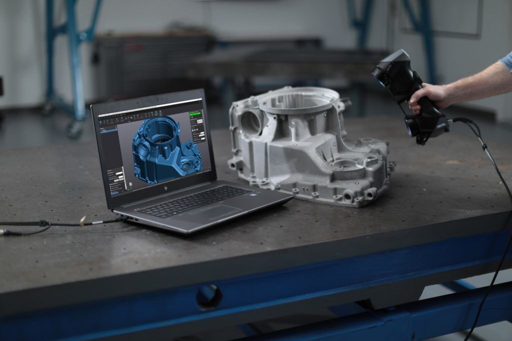
Applications Engineer
3 years at Instrumart
Mike K.
Cal & Pressure Engineering Lead
11 years at Instrumart
Brynn O.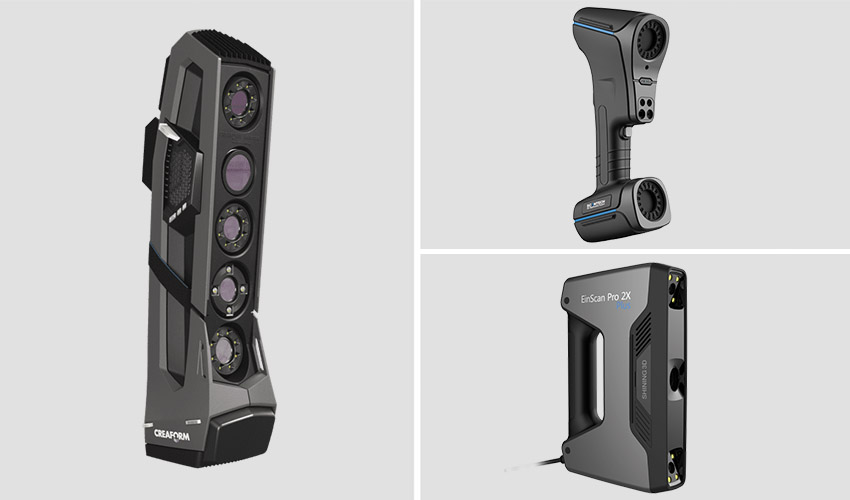 S.
S.
Applications Engineer
Shawn S.
Senior Applications Engineer
27 years at Instrumart
John A.
Applications Engineer
17 years at Instrumart
Recently Viewed
Rosemount 5708 3D Solids Scanner
Brochures
Brochure: Rosemount Level Measurement Solutions
Certificates & Approvals
Certificate: Rosemount 5708 3D Solids Scanner EC-type Examination
Certificates & Approvals
Certificate: Rosemount 5708 3D Solids Scanner PESO Intrinsic Safety
Certificates & Approvals
Certificate: Rosemount 5708 Hazardous Location Electrical Equipment
Certificates & Approvals
Certificate: Rosemount 5708 Hazardous Location Electrical Equipment per Canadian Requirements
Certificates & Approvals
Declaration of Conformity: Rosemount 5708 3D Solids Scanner
Data Sheets & Bulletins
Configuration Data Sheet: Application Evaluation Form Rosemount 5708 3D Solids Scanner
Data Sheets & Bulletins
Product Data Sheet: Rosemount 5708 Series 3D Solids Scanner
Drawings & Schematics
Type 1 Drawing: Rosemount 5708 Solids Scanner, 2D DXF
Drawings & Schematics
Type 1 Drawing: Rosemount 5708 Solids Scanner, 2D PDF
Drawings & Schematics
Type 1 Drawing: Rosemount 5708 Solids Scanner, 3D PDF
Drawings & Schematics
Type 1 Drawing: Rosemount 5708 Solids Scanner, 3D SAT
Drawings & Schematics
Type 1 Drawing: Rosemount 5708 Solids Scanner, 3D STP
Manuals & Guides
Manual Supplement: Rosemount™ 5708 Series 3D Solids Scanner Integration with DeltaV™
Manuals & Guides
Manual: Rosemount 5708 Series 3D Solids Scanner
Manuals & Guides
Manual: Rosemount™ 5708 3D Solids Scanner Integration with Ovation™
Manuals & Guides
Quick Start Guide: Rosemount 5708 Series 3D Solids Scanner
Manuals & Guides
Quick Start Guide: Rosemount™ 5708 3D Solids Scanner Manhole Mounting Tool Kit
Software Downloads & Drivers
Device Descriptors: 5708 (5708L, 5708V, 5708S) | Rosemount
Software Downloads & Drivers
Device Install Kit: Emerson 3D Vision 3. 0.020 Exe File | Rosemount
Software Downloads & Drivers
Device Install Kit: Rosemount 5708L 4.5.340 wrapped
Software Downloads & Drivers
Device Install Kit: Rosemount 5708V S 4.5.340 wrapped
FAQ about 3D scanning: technical nuances, practice, 3D modeling
3D scanners
Reverse engineering
Geometry control
Experts recommend
Author: Grigory9 Avatinyan
Author: Grigory9 Avatinyan
Grigory0vatin In the first part of the article, based on user questions, we discussed such general topics as the accuracy of 3D scanning, working conditions, the cost of equipment and services, the features of digitizing various surfaces, the possibility of automating quality control, and others. Today we will touch on some technical details, consider practical examples of scanning and the process of processing scans in software.
We will be happy to answer any questions you may have. You can ask them online , by email [email protected] or by phone +7 (495) 223-02-06. Our team of highly qualified specialists is always ready to help you in choosing and implementing the optimal solution in the field of 3D technologies.
What is the difference between the color of the scanning laser - red and blue?
The difference lies in the wavelength, and each type of backlight has its own characteristics of operation. Red has a wavelength of 650 nm, while blue has a wavelength of 445 nm, and a shorter wavelength, respectively, makes it possible to better illuminate glare surfaces due to more intense light scattering on surface microdefects, even if very smooth. Scattering on the surface of the scanned object is required so that the image of the illumination lines is visible to the scanner cameras, that is, so that part of the radiation from the laser illumination device returns to them, and is not reflected to the side at an angle equal to the angle of incidence.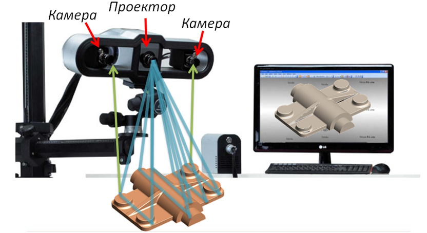
The ZG HyperScan Plus portable 3D laser scanner has 34 blue laser lines to increase scanning speed to 2.1 Ms/s
The question of choosing the type of illumination device for a 3D scanner (projector or laser) has several technical nuances. The projector provides a larger sample of scan data because it can form a different grid, a different pattern of illumination lines over a larger area of the scanned object. The laser illumination device, on the other hand, forms only a few intersecting lines with beams rotating at a high angular velocity, but many times per second.
In addition, in a laser spot moving along a line, the power density is greater than in a projector where one light source illuminates the entire area of the scanning area through the mask, and the laser beam delivers almost all the energy to a small light spot. That is, a very clear thin bright line is obtained, which is clearly visible even on glare surfaces. However, successful scanning of such surfaces is provided, among other things, by signal processing software. Also, the thin line of the laser illumination device helps to quickly and accurately capture the geometry of the surface of the scanned object at a high frame rate, which minimizes the effect of vibrations and shaking of the handheld scanner on the accuracy of the collected data.
Also Read: Frequently Asked Questions about Terrestrial Laser Scanning
What is the minimum scan hole size?
It is determined by the spatial grid step with which scanning is performed. The Creaform HandySCAN BLACK|Elite handheld 3D scanner has a minimum grid spacing of 100 microns, or 0.1 mm (this is the thickness of an office sheet of paper). If the hole is close to the grid spacing or less, then, of course, it will be extremely difficult to capture its contours. Therefore, it is advisable to scan thin holes with a minimum grid step.
The advantage of Creaform scanners is that, having digitized a part with a large grid step, it will already collect the maximum amount of information through the optical system.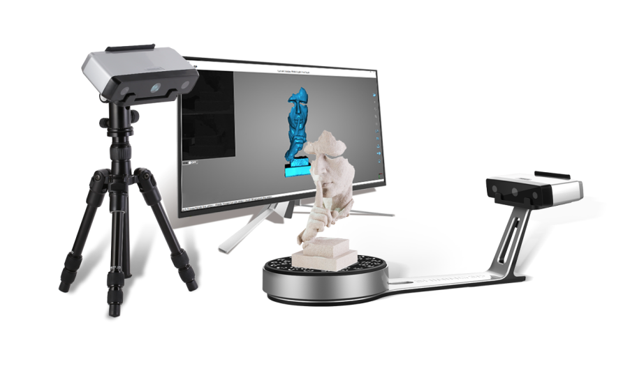 And if you need to refine the position of holes that look rough when you scan with a large step, you can simply specify a smaller mesh step value and the software will recalculate the mesh without rescanning. The edges of the hole will become sharper, more detailed. This will allow you to locate the center of the hole boundary much more accurately, even if it is thin.
iQB Technologies expert Grigory Avatinyan with a portable scanner
How will the thread be scanned using the example of a nut? And can the entire thread be scanned?
Scanning of internal holes, including those with threads, is possible, but to a depth of no more than 1 - 1.5 diameters - depends on the diameter of the hole. The thinner the hole, the less depth it will be captured by geometry. If the thread is external and its pitch is above 100 microns, it can be scanned - the scanner is able to record the geometry of the threads. Then it will be possible to control the shape of the thread profile, pitch, diameters.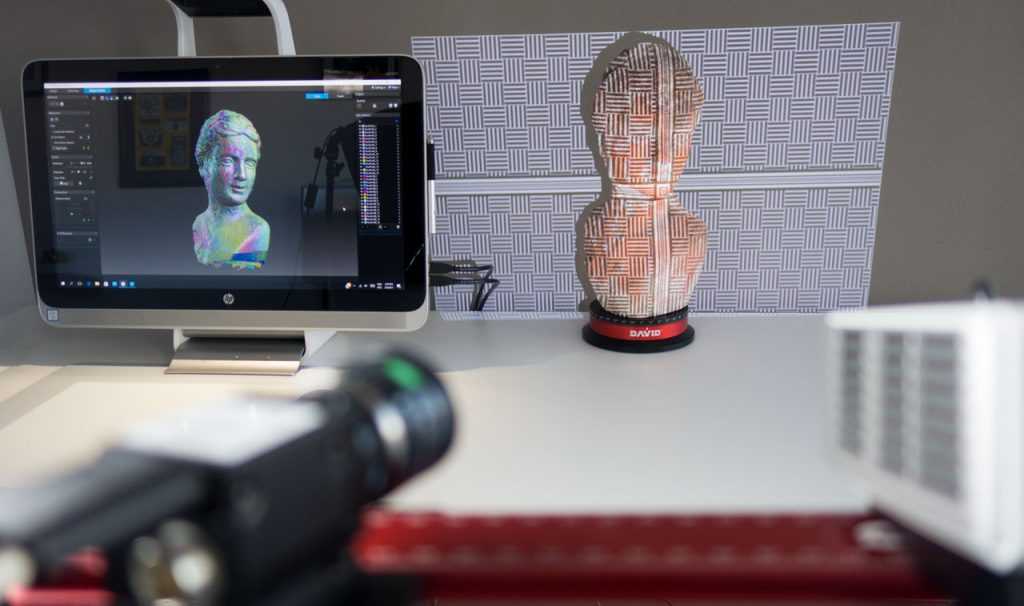 As mentioned above, a Creaform HandySCAN BLACK|Elite handheld 3D scanner or a stationary 3D scanner is suitable for this.
The nut has a small height, and if the diameter of its threaded hole is 10-20 mm, then the thread (at least the thread pitch) will be displayed quite accurately in the 3D model. It will not be possible to completely capture all the turns, but this is not required for reverse engineering. To save time when reverse engineering various parts, you can capture with a large selection (with maximum coverage) only those surfaces that we need: a plane, a sphere, cones, and others that bound the body of an object. And if, say, half of the sphere is captured, it may already be enough to build this sphere in the CAD model.
What would you recommend for scanning a curved surface, such as the bottom, with approximate dimensions of 4.2 by 1.5 meters?
It all depends on what kind of scanning accuracy you need. For objects of complex geometry with such dimensions, you can use Creaform's flagship handheld 3D scanners - Go!SCAN SPARK, HandySCAN BLACK|Elite or MetraSCAN BLACK|Elite.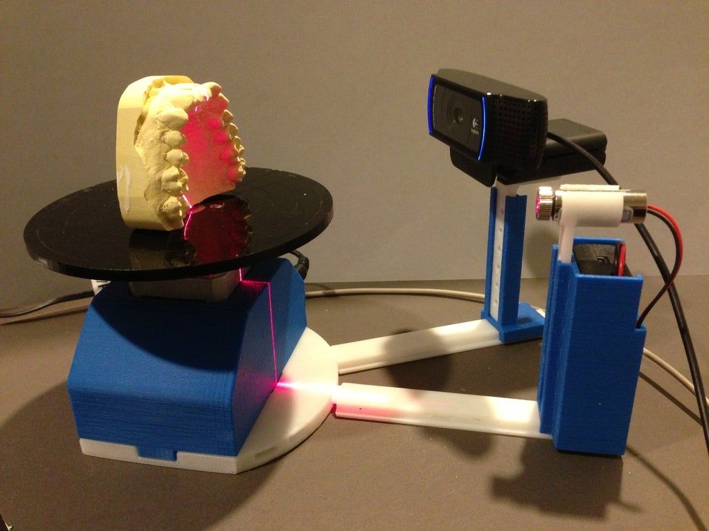 These devices provide measurement accuracy up to 0.25 - 0.05 mm. If you need higher performance, then you may also need the Creaform MaxSHOT 3D Photogrammetry System. It allows, using information from an external observation post - a photogrammetric handheld digital camera (that is, photographs of scale bars and coded marks along with 3D scanner marks), to refine 3D scanning data of large objects.
Among handheld Creaform devices, MetraSCAN models have the advantage that they work in tandem with the C-Track optical tracker, which tracks MetraSCAN movements in space, and you do not need to stick position marks on the surface of the part. If the part does not fall into the measuring volume of the tracker, then it will be necessary to rearrange the tracker from place to place, and in this case a small number of marks will still be needed.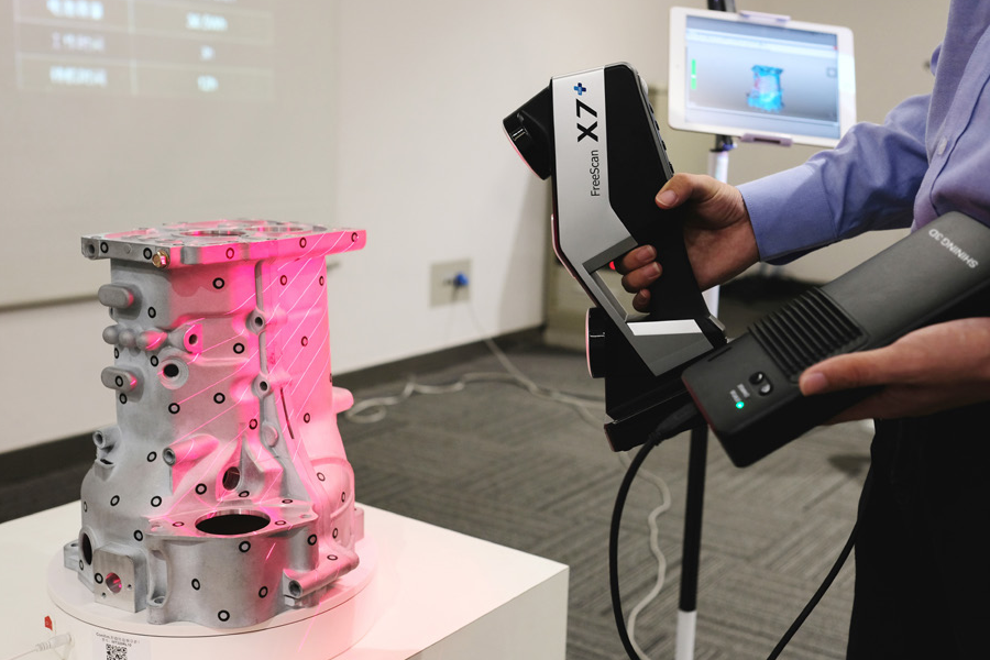
Contact us and tell us what part you want to scan, and we will offer a solution and suggest which equipment is best for you.
How do the parts of model stitch together when using a stationary 3D scanner?
With one installation of a stationary scanner on a turntable, sections of the geometry captured in different angles are stitched automatically, since the part does not move relative to the table when it is rotated and captures the angles-sections of the part geometry. And after reinstalling the model, intermediate scans are stitched according to the characteristic features of the geometry, which can be distinguished on two obtained scans from different settings.
After the characteristic points of scans from two installations have been selected, the program, using a very large sample, stitches these two sections of geometry with high accuracy, while showing an alignment error, which will inevitably occur in this case. But for this, it is necessary to indicate certain characteristic features of the geometry that are present on both scans stitched in a pair: a scratch that the scanner captured, or a burr, or asymmetrically located holes. If the part is perfectly axisymmetric, say, a shaft, but it needs to be scanned from two setups - this happens - then you might just need to stick a position mark or fix a piece of plasticine on the model, and then use it as a guide. And the hole that you get after cutting this piece of plasticine or a mark from the scan can not even be closed, because during reverse engineering there will still be a large sample of data from the 3D scanner describing this cylindrical surface.
If you need to print your model right away, making it airtight, Geomagic Design X software and even the ezScan software that comes with Solutionix 3D scanners allow you to close the hole. If this is done programmatically in a polygonal model without building a parametric one, the hole can be very accurately closed along the generatrix of, for example, a cylinder, and this piece of plasticine will not present problems. This technique is used for scanning, stitching parts without geometry features. If there are geometry features, the program will merge two scans according to a very large sample, adjusting their relative position, since you must scan in such a way that the overlap area of two scans from two installations will be very large, which provides a large sample of data for alignment.
The principles of scanning stitching described here, the techniques for scanning symmetrical objects, for example, cutting out a reference point in the form of a piece of plasticine or a position mark from a scan, are also relevant for the scanning process with manual 3D scanners, except for those associated with an automatic turntable.
How is a 3D scanned model compared to a CAD model?
When you need to check the geometry of a part, you must have either a blueprint for it or a solid CAD model. The drawing, of course, gives only linear dimensions, radii, angular dimensions and tolerances. Thus, you can either use a comparison with an existing CAD model, or measure directly from a scanned model.
By digitizing a part, you get a point cloud, that is, a polygonal model. If you have a CAD model, then using specialized software that is shared with the scanner (for example, Geomagic Control X or PointShape Inspector), you combine the scanned model with the CAD model, get a color deviation map and surface location.
If there is no CAD model, but only information about the required dimensions - say, from a drawing - you can use the same software to measure directly from a polygonal model, combining geometric primitives (planes, mathematical cylinders, etc.) with this scanned model. Thus, you will get the dimensions of the model as if you were feeling its coordinates on a measuring machine or measuring with a caliper. Moreover, in the future you will be able to do this without access to the real part, if, for example, it was destroyed or lost during the test. In addition, you have the opportunity to save the model in a digital archive - this is another important advantage of 3D scanning.
Interested in the process and methods of building a solid model.
Having received a polygonal model as a result of scanning, you import it into the software, for example, into Geomagic DesignX.
Next, you determine where you have geometric primitives in the form of cylinders, spheres, cones, tori, planes, etc. (they are recognized automatically by Design X), build them in the software using methods well known from CAD systems: extrude-rotate, extrude-cut, extrude along a path, trim the surface. This way you get a parametric solid CAD model.
3D scanner software (VXelements for Creaform, ezScan for Solutionix, etc.) usually has a mesh optimization feature. However, Geomagic software or Materialize's software products for preparing models for 3D printing provide more opportunities.
If you have a flat surface or a large radius of curvature of the surface, then the mesh will be coarser in this place without loss of accuracy, since the large radius of curvature is closer to the plane. On thin edges, the scanner automatically makes the grid step smaller, and the extremely small grid step, if we take the Solutionix D700 and C500 stationary scanners as an example, will be 28-29micron. But on thin edges, if you look at the model and measure the distance, I saw the distance between the points can be even smaller. That is, the scanner, using the data, refines the mesh on thin edges, making it more frequent. Thus, the resulting grid is obtained in some places even with a smaller step than stated in the scanner specifications.
Let's give an example of building a solid model of an impeller in Geomagic Design X. The surface of the impeller is limited by a certain parametric surface. It can be obtained, firstly, by automatic meshing of a parametric surface - such a function is available in Design X.
Secondly, we can build several sections of the blade on the grid as a 3D landmark and also draw a parametric surface through them, which we will use to build a solid body between the sections of the blade. This can be done both semi-automatically and manually. In the latter case, the surface between the sections is created automatically, but the blade section we want to create is selected manually.
Geomagic Design X also has a fully automatic function - autosurface, when the entire 3D scan is covered with sections of parametric surfaces, but at the same time you will have almost no geometric primitives, since the program uses automatic fitting. The use of this function is not always effective, the best solution is human participation. It all depends on the specific task. Contact us at iQB Technologies and we will figure out how best to solve your problem.
So, the polygonal model created as a result of 3D scanning is imported into the Geomagic Design X software, then the resulting primitives can be imported into SolidWorks. Another possibility is that a solid body already built in Geomagic can be directly imported into SolidWorks in a parametrically editable view, with a construction tree. There is also a Geomagic for SolidWorks plugin that allows you to build a CAD model from a point cloud directly in SolidWorks, thereby expanding its functionality for working with point clouds. Such approaches to solving reverse engineering problems allow you to choose the optimal solution for each problem.
Is it possible to reverse engineer a part in the absence of a full-fledged polygonal model?
Above was an example of the fact that a complete, 100% scanned polygonal model is not needed for reverse engineering. For example, you have captured enough information to know where you have a cylindrical surface, where a plane, where, for example, a conical chamfer, and at the same time you may have gaps in the mesh that did not have enough time to scan and close, or they are in hard-to-reach places. And if the scanned data is enough for further construction of primitives, then you can do without a complete model. Roughly speaking, you need to determine exactly where planes, cylinders and other geometric primitives are located in the parametric model along the scan, which will then be combined into a single parametric model. This saves scanning time.
In other words, the scan is used not as a template, but as a high-precision three-dimensional landmark for building primitives, which will be used to obtain a parametric, ideal from a mathematical point of view, CAD model.
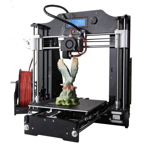
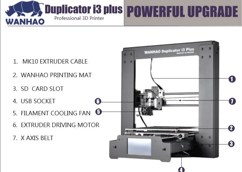
Is it possible to import the scanned model directly to the 3D printer?
It is important to define the concept of importing a scanned model directly into a 3D printer. The 3D scanner is just a high-precision sensor for capturing part geometry data. The role of the recorder and data processor is performed by the PC. After scanning, immediately from the PC, you can send the scanned part for printing, provided that it is suitable for printing, of course. More on that below.
The finished scanned model can be sent immediately for 3D printing as an STL file. If the detail is not completely digitized, then with a high degree of probability, when slicing (cutting into layers) of surfaces scanned with gaps, distortions will appear, and the print may come out of poor quality. It largely depends on the 3D printer and software. Therefore, I would recommend scanning the model as completely as possible, or closing the gaps and correcting errors programmatically (for example, in the Materialize Magics software) in the model itself before printing.
If you weren't able to scan some features - let's say deep surfaces in a hole - you can close the holes in the 3D model, again with Magics additive manufacturing software, and avoid printing errors. I already gave such an example above.
You can save/unload a model for 3D printing directly from the 3D scanner through its software. 3D printers typically require a polygon model for slicing and layering.
Thank you for your interest in 3D scanning and we are ready to answer your questions! Write to us and follow the blog posts.
Article published on 28.08.2020 , updated on 17.01.2023
History and application of 3D scanning
Share on Facebook Share on Twitter Share on Vkontakte
History of 3D scanning
The first 3D scanner, the , saw the light of day in 1960. True, he had very limited capabilities, so a lot of time and effort had to be spent to obtain a result and some accuracy of the data. After 1985, scanning devices changed to use white light sources, lasers, and darkening to better "capture" the object being scanned.
In the 80s, contact sensors already appeared, which were used in 3D scanners to digitize the surface of solid, simple objects, but this method was very slow, and the result was far from ideal. Therefore, the developers focused on the capabilities of optical technologies, which soon divided into three types according to the "coverage" zone:
- point, very slow method (point)
- capturing a specific area (area)
- strip; as it turned out, the fastest method, since it used a lot of points that a strip passed over the surface. It also provided the required accuracy of object scanning (stripe)
The 3D scanning of was of interest not only to developers from automotive and design design bureaus, but also to the film industry (digitization of people was then used to create images in animation). Companies such as Cyberware Laboratories , Digibotics have been developing their 3D Scanners. For example, the first company created the Head Scanner , which gave relatively good accuracy and could even reproduce color. And in 1994, 3D Scanners released the 3D scanner REPLIC A, which gave accurate (for that time) and fast results, it was a major success.
Since then, 3D scanners have been improved, they are more accurate, mobile, and transmit color. In general, you can find 3D scanner for any task.
3D Scan Types Each of them has its pros and cons and finds application in its field.
What is 3D contact scanning?
Contact 3D scanning involves the physical contact of a special probe with the surface of the scanned object. The contact mechanism of such scanners can be of three types:
- moving carriage with fixed measuring arm perpendicular to the object
- movable arm with high-precision angle sensors
- combination of the first two
Contact 3D Scan can be used on objects with simple geometry, but if the object has rich detail, then Contact 3D Scan can be extremely time consuming and inefficient. Also, the surface of the object must be solid.
What is non-contact 3D scanning?
Non-contact 3D scanners also come in different types:
- active
- passive
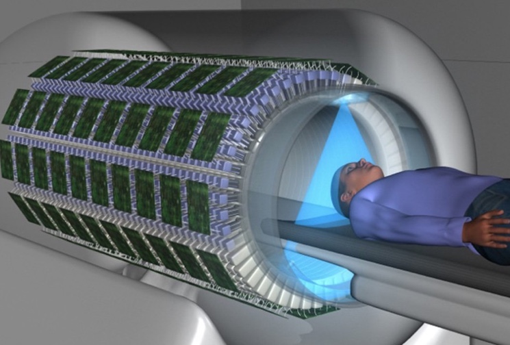
Active 3D Scanners generate a waveform that can be light, laser, ultrasound, or even X-rays. Some active 3D scanners also project a grid of white light onto the object they are scanning. This is not without reason: projection distortions from imposing on the surface of an object bring additional information for algorithms 3D scanner .
Passive 3D scanners do not emit anything, but use ambient light and analyze the reflection from the object. Roughly speaking, passive 3D scanners are a photo or video camera, they are equipped with special software that reduces the material into a single three-dimensional figure.
There are many varieties of non-contact 3D scanners , but we would like to focus on those that are used more often than others. It's time-of-flight laser scanners, triangulation , handheld laser and non-contact passive scanners. Let's consider them in turn.
TOF laser scanners
TOF scanners are active. In order to obtain information about the object being scanned, they use a laser beam, and the device itself is based on a time-of-flight laser rangefinder. 3D scanner sends a laser beam towards the object, a special counter records the time when the beam is reflected from the surface of the object. Then, using the value of the speed of light, the distance to the points on the surface of the object is calculated.
Now time-of-flight scanners can "capture" from 10,000 to 100,000 points per second. The accuracy of such printers directly depends on the accuracy of the measurement of the time of flight of the beam.
Triangulation scanners
This method of 3D scanning of also uses a laser to digitize the object. The 3D scanning process includes three participants: a laser emitter, a camera, and points on the surface of an object, which is why it is called triagnulation. The laser emitter sends a beam to the surface, while the camera fixes the places where the points fall. To speed up the process of digitizing an object, a laser strip is often used instead of a laser dot.
Handheld laser scanners
This 3D scan still uses the same triangulation principle: there is a fixing sensor, a laser beam or strip, and a hand-held emitter. Again, the emitter emits, and the sensor measures the distance to the object. A charge-coupled device or a coordinate-sensitive detector is usually used as a sensor.
The movements of the Handheld 3D Scanner during scanning can be detected by means of external tracking. For these purposes, a laser tracker with a built-in camera is often used, which determines the position 3D scanner in space. Another way to track the scanner is photogrammetry. To ensure this method, 3 cameras are used, which record the movement of the scanner in three-dimensional space. Often, both methods use infrared LEDs, the movement of which is recorded by cameras with special filters.
To determine the exact position of the 3D scanner in space (after all, it is manual and moves during the 3D scanning), special marks on the surface are used.
Non-contact passive scanners
This type of scanner works only with reflected natural light and with other types of radiation, such as infrared. For 3D scanning of this method does not require expensive equipment, a digital camera will suffice (if there are two, they will be a stereoscopic system) and specialized software. In order to obtain a 3D model of , will need to apply the "silhouette technique", which involves analyzing a series of photographs of the object against a contrasting background.