3D shadow scanner
Shadowing - LIDAR USA - UAV DRONE 3D LIDAR MOBILE MODELING MAPPING GIS EXPERTS
A ScanLook scan using the FARO at 30 degree tilt and about 7.5 high from the back of a van:
At the same time the Velodyne tilted upwards at 45 degrees, just about 1 foot higher:
Notice the drastic reduction in shadowing from the Velodyne scan.
*Note: The top picture shows the amount of shadowing that can and will occur using any single line, single scanner mobile system. It is very similar to the shadowing from a static scan (hence the many setups required with a static scanner to capture most scenes). Using a dual, butterfly pattern with single line scanners will significantly reduce the amount of shadowing but it will still not be nearly as complete as the Velodyne HD32 with 32 lasers in a 40 degree FOV.
| A single FARO setup similar to the below. As you can see you have large shadows behind cars and trees. |
| Two FARO's in a butterfly setup similar to the below. As you can see you have much less shadow as a result of using two FARO's set up at 30 degree tilt and a butterfly setup. |
| Looking from the top down with a single FARO setup. As you can see you have large shadows behind cars and trees. |
| Looking from the top down with two FARO's in a butterfly setup. As you can see you have much less shadow as a result of using two FARO's set up at 30 degree tilt and a butterfly setup. |
Notice the drastic reduction in shadowing from the Velodyne scan.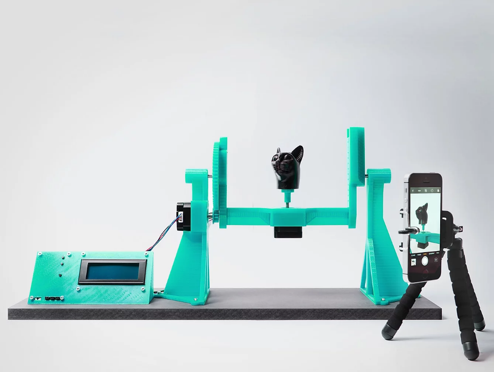
*Note: The top picture shows the amount of shadowing that can and will occur using any single line, single scanner mobile system. It is very similar to the shadowing from a static scan (hence the many setups required with a static scanner to capture most scenes). Using a dual, butterfly pattern with single line scanners will significantly reduce the amount of shadowing but it will still not be nearly as complete as the Velodyne HD32 with 32 lasers in a 40 degree FOV.
| The Disadvantage. We are often asked how laser scanning range affects the mobile laser scanning system (i.e. ScanLook). In particular, ScanLook utilizes the FARO FOCUS 3D (F3D) with an advertised distance of 120m for the 120 and 330m for the X330 and the Velodyne HD32 with a distance of 70 to 100m (depending upon the literature). |
The FOCUS Success.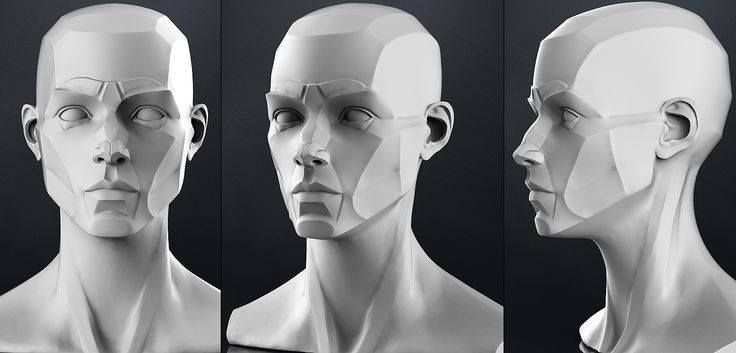 Let’s step back for a moment and evaluate the F3D from a static scanning perspective. Up until October 2010 FARO was virtually unknown to surveyors and mappers. Since that time the F3D has completely dominated the static scanning market. Its range is much less than that of many of its competitors yet it has yielded an unexpectedly high volume of sales. This can only mean that the range is either not that important or there is something else being overlooked. The initial reaction by many speculators was that it was too small, light, and fragile with a short scanning range. Apparently they were wrong. Sure, the price is drastically reduced but that’s nothing new. There are other systems available for much less and yet they don’t have near the appeal. If the F3D was a fad, it would have passed by now. We can only assume then that users are buying the F3D and making a profit using it. The range must be significant and competitive in some markets.
Traversing & Surveying. Thinking as a surveyor using a total station, distance is important. It makes a big difference in traversing. While traversing, the longer the legs of each traverse side the quicker the job can be finished. In addition, a total station can be used for topographic collection. In this case, the rod-man must walk to each distinct point to collect the XYZ data and other attributes. The more information necessary, the longer it takes at each station. If the traverse stations are set far apart, then not only does the time increase to collect the topography but so does the difficulty obtaining line-of-sight to all data necessary. Often this requires additional setups with the total station (and level).
It would be foolish in most cases to use a static scanner simply for traversing. It can be done but it would be painfully slow. Scanning is done to capture the 3D environment. Traversing just happens to be part of the workflow to join each setup into a seamless result. The fame that the F3D has is it can do short legged setups very, very fast with a light instrument so it’s not burdensome in the field.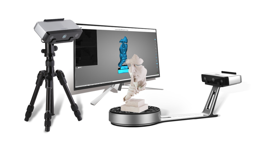 At each setup everything within a 100 to 150 feet radius is captured.
Some manufacturers have much greater range scanners but can they scan down a roadway or through a neighborhood faster? Not usually. The reason is influenced largely by the instrument height, the angle of incidence, and the lack of line of sight to all areas of interest. At about 5.5 feet instrument height the angle of incidence quickly degrades with distance as seen in this table:
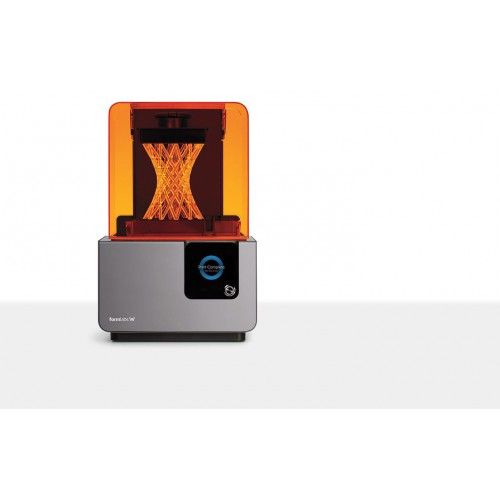
B9 Scan 500 | Best for Jewelry & Small Articles
SHADOW BANDS
HEIRLOOM REPLICATION
GEMSTONE SCANNING
JEWELRY REPAIR
LINK REPLICATION
Increase your throughput.
Reduce your error rate.
Highly intuitive and efficient, the B9 Scan 500 enables you to replicate models within 5 µm accuracy. And with a robust internal computer, it makes the scanning process entirely automatic and customizable. In addition, 3D modeling is now quick and easy, requiring only a monitor and a mouse to achieve highly detailed scans in minutes.
Bundled with Leios 2, the most reliable software for processing 3D scans, mesh editing and reverse engineering, the B9 Scan 500 is the complete solution for the jewelry and manufacturing industries.
“I’ve been in the jewelry business for 40 years. No one else can do this. After the scan, I was blown away and called my customer back to give him the great news that every last detail was captured, and that the new heirloom replica would be amazing.”
Time is money.Our 3D scanner can save you both.
Shadow Bands
With the B9 Scan 500, you can scan any ring in under 5 minutes to make the perfect fitting shadow band.
3D Heirloom Reproduction
3D Scanning allows you to digitally capture heirloom jewelry and make desired changes, improvements, replicas, or customizations.
Gemstone Scanning
For custom bezels and mountings, accurately scan gemstones to ensure a quality fit the first time.
Jewelry Repair
Complete hard-to-fabricate jewelry repairs by scanning the piece and designing the perfect fitting detail.
Necklace and Bracelet links replication
Replicating bracelet links with traditional methods usually introduces shrinkage, resulting in non-fitting links. The B9 Scan 500 accurately scans a link that can be scaled up as needed to ensure the proper fit after assembly.
| 3D SCANNER TECHNOLOGY | Structured LED Light |
| CAMERA RESOLUTION | 1.3 Megapixels |
| LIGHT SOURCE | 100 ANSI-lumen, Blue Light |
| ROTARY STAGE | 2 Axis Movement |
| 3D ACQUISITION VOLUME (WxDxH) | 90 x 80 x 55mm |
| ACCURACY | 5μm |
| OUTPUT FORMATS | STL, PLY, OBJ, ASC |
| INTERFACE | USB 2. 0 High Speed, DVI/HDMI 0 High Speed, DVI/HDMI |
| MEMORY | 32GB Ram |
| MACHINE SIZE (WxDxH) | 275 x 465 x 450mm |
| WEIGHT | 19kg |
| COMPUTER | Internal, Only Monitor & Mouse Needed |
| OPPERATING SYSTEM | Windows 10 64 bit |
| HARD DISK | SSD 1TB SATA |
| WARRANTY | 1-Year |
Want to see how easy it is to get a high-resolution 3D scan with the B9 Scan 500? Watch the demo video to see a complete walk-through of the process.
Click below to watch the demo!SEE THE DEMO
Check out some of the incredible things being created with the help of the B9 Scan 500!
3D scanner by proxy, or laziness
Mikhail Naumov (Mic Nau)
A designer must be lazy in order to achieve maximum results with minimum means.
Viktor Plyshevsky
Hello everyone!
First I want to express my gratitude and respect to Fiend3d for the wonderful tutorial that inspired me to write this article. I have always experienced envy in half with delight, watching how the physical world turns into a set of equations in the mind of a mathematician. nine0007 I also want to warn against attempts to take my exercises for ready-made technology. It's just a fun experiment. If someone finds it useful, it's not my fault :)
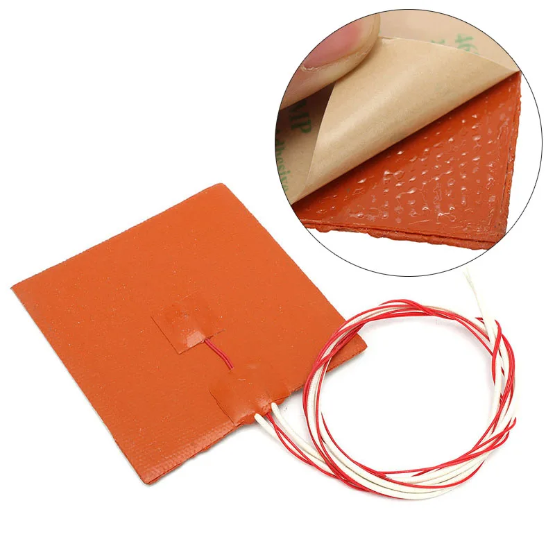
So, let's get down to business! Discussing how to make a three-dimensional object out of a flat picture, I remembered the depth channel (Z-buffer). All we need is to get a photograph of the object with the illumination uniformly decreasing in depth. And preferably without perspective distortions. Most of us have such a camera on our desktop (or at least on the next table). This is a regular flatbed scanner. nine0003
But of course, not everything is so simple.
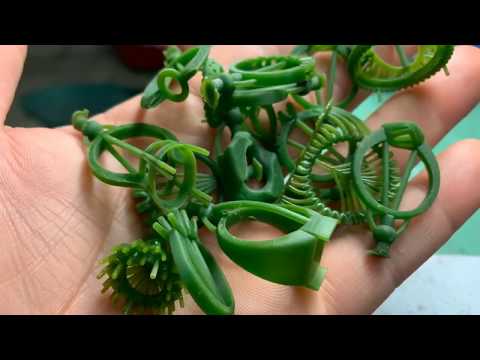
Problem #1: objects have their own color. And dark spots differ little from shadows. I solved this problem simply. I took an object made of plaster :) Here it is:
By the way - I had to wash it a little :) Of course, if you want to take something not from plaster - there is always a can of paint :) I scanned with low resolution, but 16 bits per channel to preserve the nuances in the shadows and highlights. By the way, keep in mind: the location of the shadows depends on the direction of movement of the scanner carriage. nine0003
A bit of Photoshop next. I took the red channel (channels/split channels) and recorded it as a separate file (this is better than a simple "discoloration" - desaturate). Yes, I almost forgot: it's worth "cutting" the object and filling the background with black. And it's not bad to additionally highlight the most protruding places (don't grumble, it took no more than 15 minutes): Explain to 3DS Max what to do about it.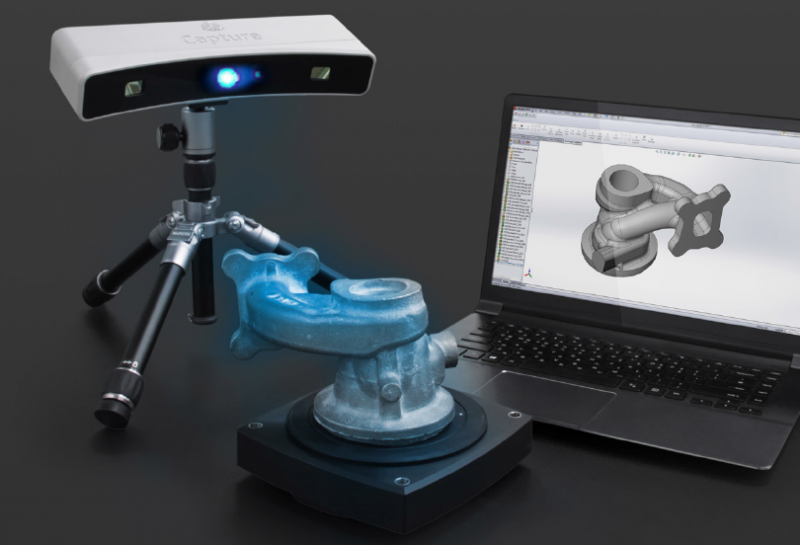 The astute reader is already screaming: "Display! Display!" - And he's right! :) But I don't want to use a display card when rendering, it's more convenient to work with geometry. So - the Displace modifier, which I applied to a regular Plane object. In order not to suffer with the fit, the map was brought to the proportions of the object 3x4 (1500x2000px):
Oops! Somehow I imagined it differently... So problem No. 2: the regular grid divides the object into squares , as if "pixels". If we increase its frequency, we quickly fly out for a reasonable number of polygons. In addition, the picture is slightly "noisy". Obviously smoothing is needed. We remove micro-noises directly in Displace (Image/blur), macro-irregularities using the Relax modifier:
"Let me!" - the indignant reader will say, - " Where are the small details? What were you fighting for??"
Yes, and this is problem №3 . It is relatively easy to solve. From the same picture we make a bumping map, of course normal bump. (I used a small free program Сrazybump )
Now it would be nice to remove all unnecessary things.And what are these nasty stains along the contour ? the shape of the object. The scanner cannot look around the corner, and where the scanned map ends, crap begins. So we just cut off these parts completely. No need to suffer and aim. Use the opacity map. Remember, I asked you to "cut" the picture first? You should have kept the alpha channel!0003
Doesn't look too much like plaster, you say? Well, it's time to include illumin -shine:
and finally in movements
Here are the final layouts for modifiers and material settings:
Fucked 2x1800/ATLON64/2GB, Win2000SP4, Autodesk 3DSP4 , V-Ray 1.53RC1
I hope I managed to entertain the audience a little :) thanks for your time!
Mikhail Naumov a.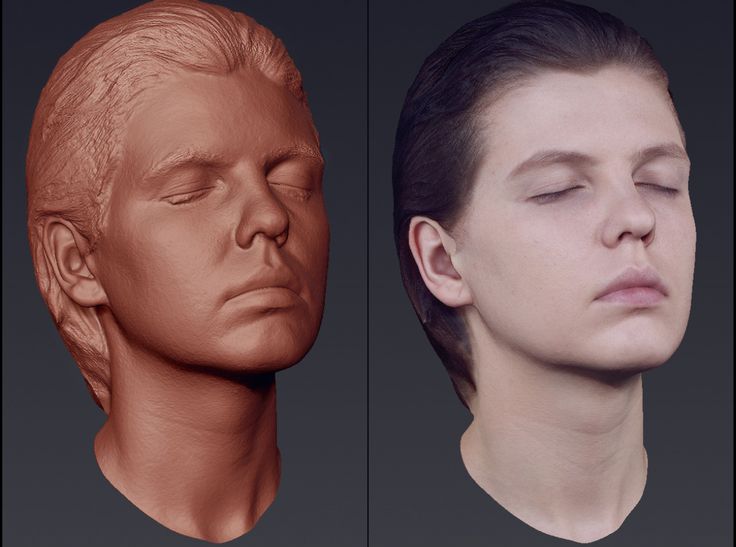 k.a. Mic Nau
526 0 850 31
19
2007-12-05
Good lesson. i liked it :)
2007-12-05
But how to completely make a model in all 360 degrees?
2007-12-05
yes the lesson is not bad... I get good stucco molding in the typical way... But it's not a 3d scanner... and unfortunately Displace can't be converted into a model...
2007-12- 05
if the semitrich model, then you can apply Miror. if not, then it’s okay to connect the two sides somehow +) ... the sense is crooked somehow ....) I didn’t get it right :(
2007-12-05
I liked the lesson! Only I’m too lazy to repeat it :)
2007-12-06
convert to geometry)) (yes, not in 3d max) but you can)) we will not disclose in which software specifically BUT)) 2dimson 3d )) unfortunately I don't think that having 1 mona picture will make the whole model ))
2007-12-08
1) Gygygy .. The display is excellent and in max it is distilled into geometry))) I will not say "connect the Brain" BUT.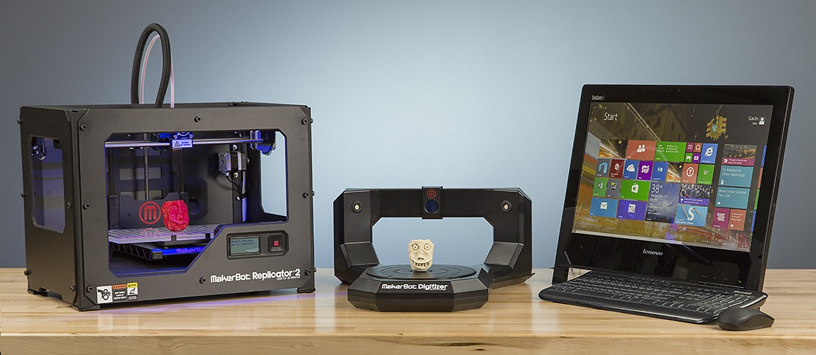 2) The article is funny. As an option for the lazy - will do. Unfortunately, the free program CrazyBump - gives a normal map that is remotely reminiscent of the truth. And to the same regret, most people for some reason do not see this. \u003d \ Relief - and hurt yourself. And the fact that you put it in a brazen stupid photo on the bump and get + - the same Nonsense .. no one understands. 3) The author forgot to mention the intricacies of scanning. I'll clarify - Fotik will not work - you need a scanet with the ability to "Volumetric" scanning. Do not be afraid of this word, it has nothing to do with 3D. Simply Previously, scanners had a focus point that was located just above the surface of the glass, and everything further - Blurred. Now almost all scanners work like cameras - ie. take a picture coherently deep into a long distance. those. like volume. and not a flat sheet.. And the second and most important thing is that you need the same random-dimensional and unidirectional light.
 That is why they use a scannet. The effect of depth is obtained due to the attenuation (scattering) of light and, accordingly, the decrease in its intensity. Those. - When scanning, the room must be Dark. so that extraneous light does not spoil everything. Last post: In any case, the result is unimportant. And in terms of time and crap .. hmm .. a normal, not armless modeler during the same time can easily sketch such a model in 3d. in addition, the quality of the Form will be higher .. and the detailing .. 15 minutes in the brush (again, for the less experienced) P / s / why I say all this so confidently - I myself did Exactly the same experiment about 5 years ago. )) if not more. nine0003
2007-12-09
2 Shiva: CrazyBump really gives normal bmp far from the truth. But "in a brazen stupid photo on the bump" - still worse - checked :) The author did not mention the intricacies of scanning quite deliberately, so as not to clutter up the article. But about the fact that the room should be dark - yes, I confess, I just forgot. Probably because it's always dark here :) And finally, about "lightly sketching" - if it's not a secret, how long did it take, for example, for this model: http://img192.imageshack.us/my.php?image=demon7xs.jpg ? :) And really - thanks for the qualified answer! It was not in vain that I wrote at the beginning that this is "just a fun experiment." The actual application of such technologies (even if everything were perfect) is very limited... At best, put the figurine on a shelf in the interior, and even then, do not fly close to it... Thanks to everyone who took the time to read to the end :) Experiments, however, continue... but in other directions
2007-12-09
I read somewhere the way of such entertainment. There, the normal map was obtained by photographing the object alternately illuminated from three sides along the coordinate axes. The resulting pictures are thrown on the channels. further clear.
2007-12-10
Misha, thanks for an interesting test! :)
2007-12-12
2 Mic Nau :)) I answer - this model took .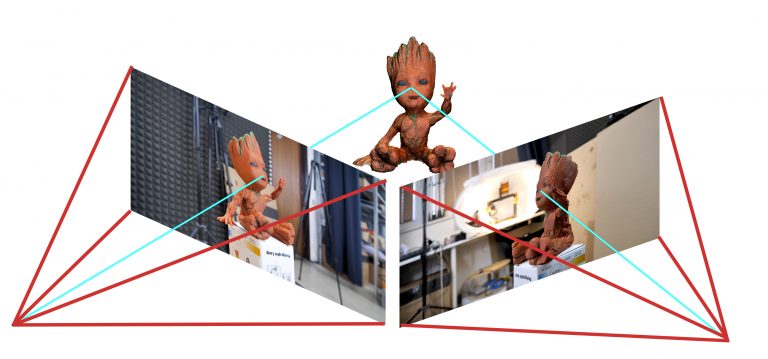 . hmm .. so not to lie - 15 minutes of a lunch break. During these 15 minutes, it was First a classic Alien with a big head, then a zombie from the Iron Maden group, and only then this Elk ..) and then another 20 minutes dabbled with retopology in Silo - redrawing the grid neatly. 2 Taras Burlin: yeah, there is a way. much better result. But, there are some drawbacks - shadows .. That is. illuminating from one side, we get shadows cast by protrusions .. But .. if this is a small bas-relief (modeling) - then it turns out almost 90% original.. if you want a display, if you want a Normal map.. and Very accurate and high quality.. eh.. if it were not for the shadows.. =\
2007-12-15
time of work activity.
2007-12-15
2 Fiend3d :)
2007-12-22
why in the original the horse's mane is flat, and as a result - some kind of convex?
2008-01-15
dimson3d I think just take a photo from both sides, i.e. from both sides and all
2008-01-17
this is a good way to make a symmetrical model and poor quality, but this horse is not symmetrical at all. I would make polygons, the details of the wings and muzzle - bump or shake with brushes.
2008-05-26
But they didn’t try to scan their physiognomy
2008-05-26
[smile=04] the first thing that came to mind... I was too lazy to make up
2004 cool if you need to make a bas-relief.
Transforming nature into jewelry with 3D scanning When asked about the areas in which 3D scanning is used, most people will not hesitate to answer that such equipment is most often used in industry - in metrology and reverse engineering.
Until quite recently, the above industries were almost the only areas of application for 3D scanning, but the situation has changed dramatically in recent years. Modern 3D scanners such as the EinScan Pro 2X have proven that 3D scanning technology has a myriad of applications ranging from small hobby projects to highly professional reverse engineering. The EinScan Pro 2X line of 3D scanners has enabled new users to significantly reduce the initial costs associated with bringing 3D scanning and modeling into production, resulting in an unprecedented growth in creative applications for these technologies. nine0003
With modern 3D scanners becoming more affordable and easier to maintain, many businesses that were previously unable to introduce 3D scanners into production due to the high cost of equipment are now actively using 3D scanning technologies to improve business processes . Schnider & Hammer AG is one of the pioneers of 3D scanning, and today we're going to take a look at one unusual project that the company was able to complete with the EinScan Pro 2X scanner. nine0003
Characteristics of EinScan Pro 2X
Source: top3dshop.ru
A few words about Schnider & Hammer AG Founded in 1993, Schnider & Hammer has specialized in traditional jewelry making for over 25 years, but has always shown an interest in modern technology and its application in its own production.
Since its inception, the company has worked with 3D design and rapid production tools to deliver quality products to the market in the shortest possible time. The company's craftsmen create unusual and surprisingly beautiful jewelry, such as the impressive collection of Weissenstein bracelets.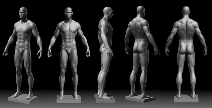 nine0003
One of the jewelry house's projects was to create jewelry that would imitate nature, exactly repeating its beauty and character. The surfaces of trees, stones, and other natural objects provide inimitable, delightful patterns for jewelry, but the implementation of these designs using traditional jewelry manufacturing methods has proven too difficult. Simply put, forms that exist freely in nature are very difficult to reproduce by hand in the workshop. nine0003
Choosing the right 3D scanner
After much deliberation, Schnider & Hammer decided to purchase a 3D scanner. The craftsmen were interested in this technology and knew that a professional 3D scanner would help overcome the problem that the manufacturer faced when creating nature-inspired designs. There are many 3D scanners on the market, but not every model meets the specific requirements of the company. The EinScan Pro 2X proved to be exactly what master jewelers were looking for: a professional-grade 3D scanner at a low initial cost.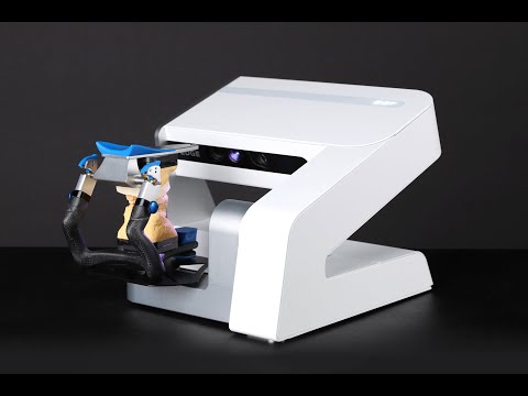 In addition, the EinScan Pro 2X is very user-friendly for the inexperienced user and can be used in a variety of business areas due to its versatility. nine0003
Using the EinScan Pro 2X 3D Scanner in Jewelry Making
Schnider & Hammer's biggest problem with the EinScan scanner was that the scanned models were provided by nature, meaning they were outdoors. All optical 3D scanners use light to study an object and build a 3D model of it, which means outdoor scanning is a huge challenge, regardless of scanner type. The company also needed a way to power the scanner outdoors, as all scanners require an external power source to operate. nine0003
The EinScan's wireless battery compatibility allowed makers to go outside with laptops and scan the desired objects, as long as there was enough shade on the surfaces of the scanned areas. The surface area of the trees met this requirement, as the leaves from the tree's canopy provided enough shade for the scanner to work outdoors.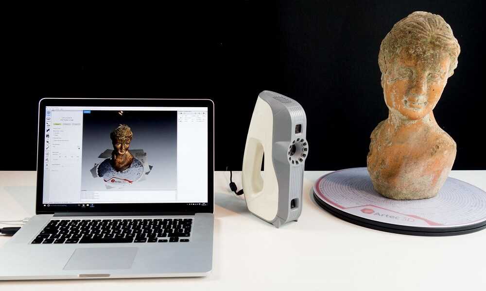
The scanner collects data quickly so that within minutes a file from the EinScan software can be sent to a 3D modeling software. The finished digital model has a high level of detail, reflecting even the smallest bumps and grooves on the surface of the tree bark. This level of detail can only be created by nature, and it is this property that Schnider & Hammer plans to include in their jewelry collections. The scan result fully reflects the natural original and can be modified and edited using CAD software. nine0003
Jewelery or any other items inspired by nature are often unable to convey the beauty, naturalness and energy of the natural prototype. 3D scanning provides a safe way to recreate and digitize the world around you, while the EinScan Pro 2X feature-packed 3D scanner allows you to use 3D scanning technology with ease and without a high initial investment.
Scanning process with EinScan Pro 2X 3D scanner. nine0200
Scanned data in EXScan Pro software.
3D modeling in Rhino3D.
3D modeling in Rhino3D.
Visualization of the finished ring model.
The finished 3D model corresponds to the required shape of the future piece of jewelry. This time, the company's craftsmen decided to transform the tree bark into a ring, but the scan patterns can also be used with different shapes and sizes. The finished part can then be manufactured using traditional manufacturing tools, helping to keep the look and feel of the products up to par. nine0003
Output
The EinScan Pro 2X line of 3D scanners has reduced the initial cost of 3D scanning and design for new users, leading to an increase in the use of 3D scanning technologies in creative fields. Traditional industries that use manual production tools are actively adopting 3D scanning to optimize their own business processes. 3D scanning and its application to various purposes has never been more accessible than with the EinScan Pro 2X 3D scanner line.