3D scanner reprap
Ciclop - RepRap
Ciclop 3D Scanner Documentation
Main page | Ciclop 3D Scanner Buyer's Guide | Ciclop 3D Scanner Build Manual | Ciclop 3D Scanner User Manual | Ciclop 3D Scanner improvements
Ciclop
Release status: working
| Description | 3D Laser Scanner |
| License | CC-BY-SA |
| Author | User:bq |
| Contributors | CowTech |
| Based-on | None |
| Categories | 3D Scanner |
| CAD Models | |
| External Link | GitHub |
Ciclop 3D Scanner
Ciclop is an open source 3D laser scanner with a rotative platform. It has been developed from scratch by BQ, and now it has been released to the community, under Creative Commons Attribution-ShareAlike 4. 0 International License.
This 3D Scanner is composed by a structure of 3D printed parts, threaded rod, a Logitech C270 web cam, two line lasers and a turntable platform with a stepper motor.
Related to this device, Horus, a complete desktop application for 3D scanning, has been developed also from scratch.
In early 2015, CowTech Engineering released their version of the Ciclop, raising over $183,000 USD on Kickstarter. They made some changes to the physical design, but still use Horus as the scanning software. The CowTech version uses adjustable laser holders and connects the scanner using laser cut acrylic instead of threaded rod. They also redesigned the printed parts and reduced the 3D printer build volume needed to make the parts at home.
Specifications
| CowTech Ciclop | BQ Ciclop (via Lulzbot) | |
|---|---|---|
| Scan Time | 2-8 min | 2-8 min |
| Resolution | 0.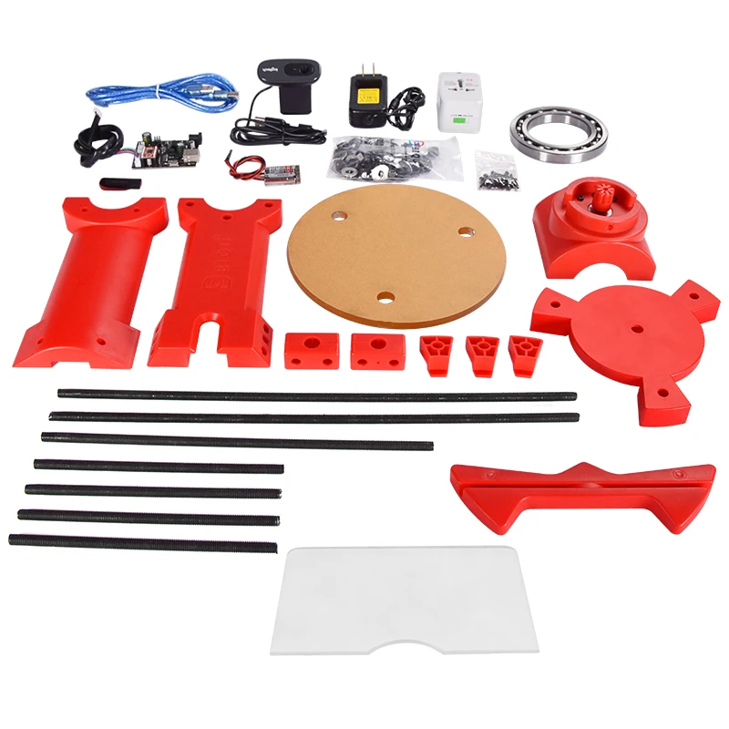 5mm 5mm | 0.5mm |
| Cost (USD) w/o Printed Parts | $119 | na |
| Cost (USD) w Printed Parts | $159 | $400 |
| Scan Area (mm) | 200 x 200 x 205 (h) | 200 x 200 x 205 (h) |
| Adjustable Laser Position | Yes | No |
| Frame Material | Laser Cut Acrylic | Steel Threaded Rod |
Both the Ciclop and Horus are works in progress, and the developers at BQ and CowTech would appreciate it if users shared any modifications with the open source community to continue development of these projects.
Contact on the Google Group or send an email to [email protected]
Resources
Most the important resources for assembling, calibrating and using the scanner, CAD models and .stl files, as well as Google and FB communities from BQ and CowTech are compiled in one place at the CowTech Resources tab. For more detailed resources, particularly pertaining to the development of Horus, please explore the GitHub and DIWO links below.
GitHub
- Sources
- Wiki
- Background / Scientific documentation
DIWO
- Presentation
- 3D Design
- Electronics
- Firmware
- Software
Where to buy?
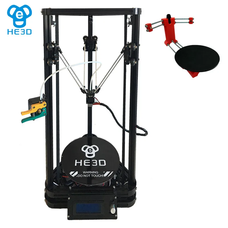
- he3d
- CowTech Ciclop 3D Scanner
- HE3D Ciclop DIY 3D Scanner Kit Free Worldwide Shipping 130 USD |3D Printers Bay
He3d scanner - RepRap
From RepRap
Jump to: navigation, search
He3D-Scanner
Release status: working
| Description | Based on Ciclop scanner. |
| License | GPL |
| Author | User:He3d |
| Contributors | |
| Based-on | Ciclop |
| Categories | 3D Scanner |
| CAD Models | none |
| External Link |
Contents
- 1 Tips
- 2 New workmanship
- 3 Assembly instructions
- 4 Tutorial on Youtube
- 5 Help and Support
- 6 where to buy
- 7 Photos
Tips
- This kind of scanner belongs to desktop 3D scanners, which can not match with industrial standard scanners, and it is not suitable for scanning irregular and complex objects, only scan nearly cylindrical object, the effect will be more ideal, there are many factors affect scan result.
 like scanned objects, environment and light. there is a big relationship between them, so we recommend you scan in Constant Light Studio, scanning results will be better.
- for installation and final you can scan object, it needs you own a certain handle ability and related knowledge, as it is open source, you can search on line and communicate with others, we can not guarantee that all the customer can operated it well, as there are too many factors affect the results, but we will try our best to provide you support, this project is also in continuous improvement, I hope we can work together!
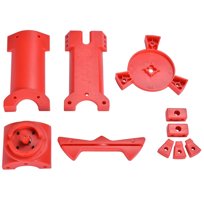
New workmanship
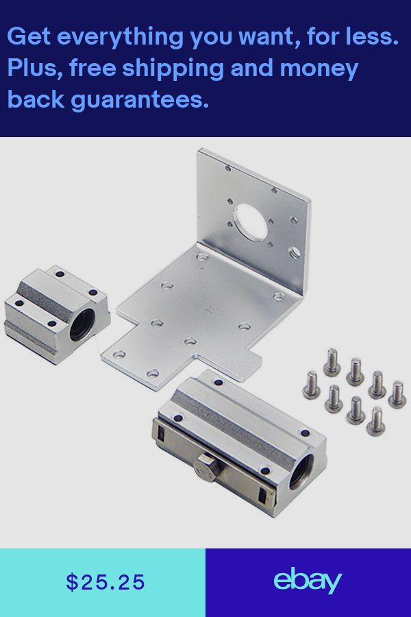
- For below 2 plastic parts, we updated the design and new workmanship, now it is plastic injection molding.as it has win much appreciation from our customer, for the rest of printed plastic parts, we will also updated to this new workmanship.
- The advantage of plastic injection molding.
- The surface of injection molding plastic parts is more smooth and clean
- Compared with printed plastic parts, You do not need to fix it
- It is more durable than printed plastic parts
- Two big advantages of the new design
- It is more easy to install
- You can stable the board on this plastic parts
- Instruction of assemble this 2 plastic parts
Assembly instructions
- Tutorial
Tutorial on Youtube
- Assemble vedio
- Calibration vedio
Help and Support
- You can download the STL file from here:mediafire.
 com
com - Ciclop scanner intruction on Reprap.org
where to buy
- 3D Printers Bay
- 3dprintersonlinestore
- reprapmall.com
- reprap.cn
- aliexpress.com
Photos
Almost DIY 3d scanner for home / Sudo Null IT News scanning is out of the question.
But the main plus that I took out from the article is the David-3D scanning program, which really has a good manual in Russian and, importantly, buying a license is the last thing required, since the free version is limited only to saving the scan result. Everything else works in full, which means that it is quite possible to test the program, settings and your hardware as much as you like. And if you don’t need the result with high accuracy, then you can do without buying a license at all. nine0005
I needed accuracy, since the main thing I wanted to scan was miniatures from the Warhammer board game (so that later I could change them as I wanted and print them :)).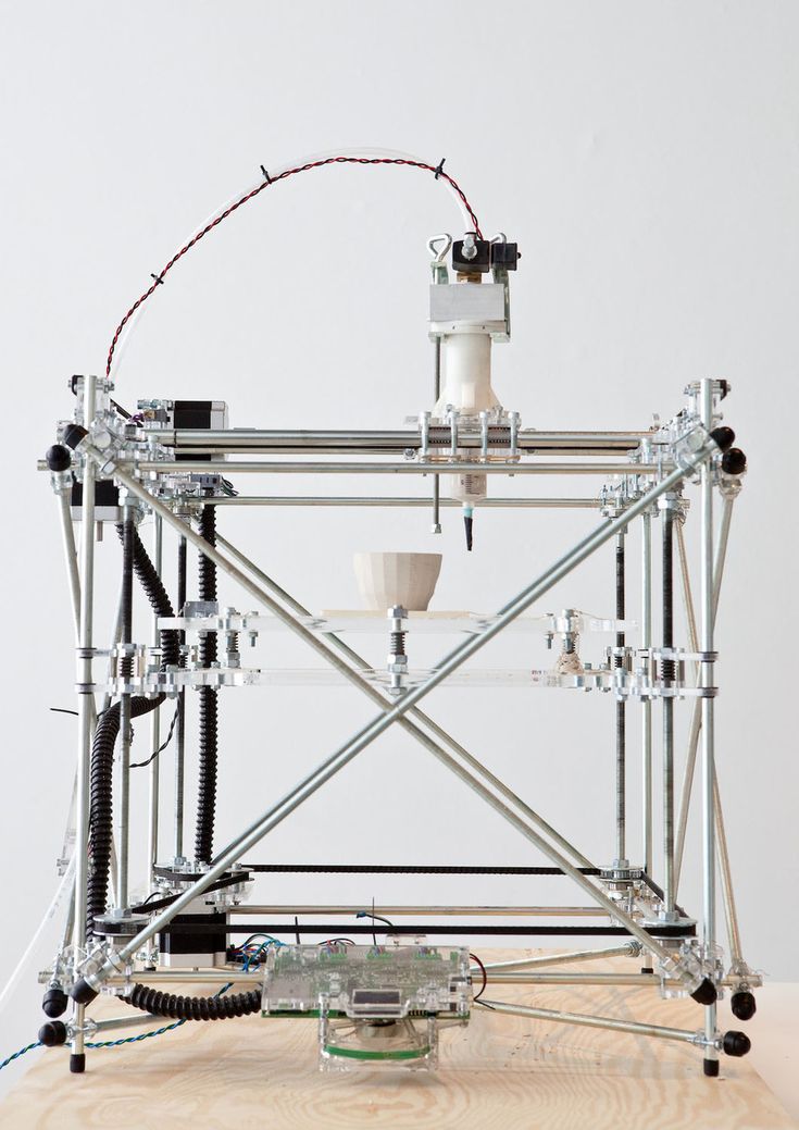 The height of these "soldiers" is only 3 cm, but this does not prevent them from being very detailed.
If you do not need to shoot such small objects, then your equipment requirements will be lower, which means that it will be much easier to assemble a similar scanner for yourself.
The principle of the program, and accordingly scanning, is well described in the article, which was linked above (I think it is not necessary to duplicate this). It is advisable to read that article first, as this one will be in some way its logical continuation. nine0003
But let's start in order. What you need to try 3D scanning at home:
1 - projector.
2 - webcam.
That's all, the short list turned out surprisingly well. However, if you want to get very accurate and high-quality scans, then you will have to modify some things with pens. Of course, you can’t do without additional costs, but in the end it will still cost less than buying any of the commercially available 3D scanners, and the quality of the result can be obtained much better. nine0003
Now, in order and in detail.
PROJECTOR.
I, like the author of the previous article, started my first experiments on scanning with a laser pointer, but they immediately showed how inconvenient this method is. There are several disadvantages here at once:
- the impossibility of obtaining a beam with a sufficiently thin line. Moreover, when you turn the pointer, the distance from the lens to the object changes, which means the focus is lost.
- if you need to scan regularly, turn the laser pointer with sufficient accuracy and smoothness by hand is very difficult, and tiringly easy - the hands are not such a stable tool when it comes to a long time. nine0005 - you have to scan in the dark so that only the laser line is visible and nothing more.
And if the second drawback can still be dealt with by creating a special rotary mechanism (although this is already not such an easy task, in any case, this cannot be done in 5 minutes on the knee), then getting rid of the first drawback is more expensive.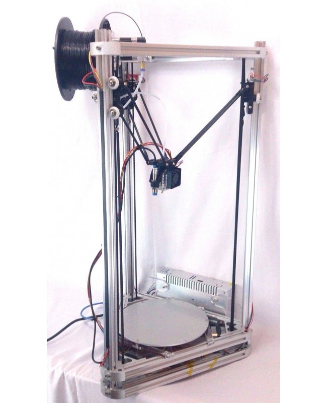
When I realized all this, I decided to try scanning with a projector, for which I borrowed some simple model from a friend. nine0003
A small clarification should be made here - in the last article, the author mentioned the possibility of scanning using a projector, although the proposal was, in my opinion, very strange -
A projector with a powerful lamp is suitable, the light of which must be directed through a narrow slit to the object being scanned
This may have been the only option in earlier versions of the program, but in version 3 that I experimented with, the projector was used much better, because there's a feature called Structured Light Scanning (SLS). Unlike laser scanning, the projector immediately projects a grid of vertical and horizontal lines of various thicknesses onto the object, which reduces the scanning time by an order of magnitude and allows you to automatically shoot the color texture of the object. Well, with good focus, a 1 pixel wide line is much thinner than you can get from an inexpensive laser pointer. nine0003
Unfortunately, I didn’t take pictures from those first experiments, and there wasn’t much to take pictures of - the projector is on the table, next to it is a webcam, all of this looks in one direction :) However, even such a simple design showed that this option much better both in terms of scanning speed and quality. Then I decided to buy myself a projector for these purposes.
The criteria for choosing a projector were simple - higher resolution, lower price and dimensions :)
The choice settled on IconBit Tbright x100 - an ultra-compact DLP LED projector, 1080 resolution - at that time it seemed to me that you couldn’t imagine better, but as it turned out later, I was wrong, although while working with it, I got a lot of interesting experience. nine0003
The first problem that occurs when scanning a small object with a projector is that for best results, the size of the projected grid should roughly match the size of the object being scanned.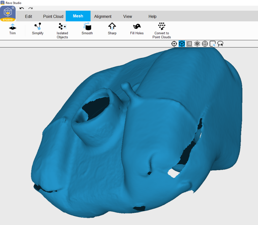 This projector made it possible to obtain the smallest screen diagonal at the closest focus - about 22 cm. Agree that against such a background, a miniature 3 cm high is far from the concept of "approximately equal sizes." The answer was found on the official forum - people in such cases install camera lenses on the projector for macro photography. Given the small size of the projector lens, I opted for marumi lenses with a thread diameter of 34mm. nine0003
Using two of these kits, I managed to get a projector screen with a diagonal of only about 3 cm. Which turned out to be quite enough to make my first microscan -
This is a single scan, therefore there are “holes” on the model, torn edges and etc. By turning the coin and scanning from different angles, you can get several of these scans, which are subsequently combined into one object (the scanning program itself allows you to correctly combine different scans, stitch them together and save them as a single object).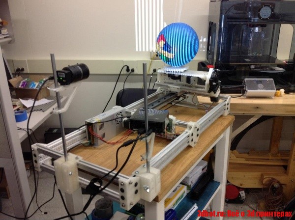 In the process of stitching, the shape of the object is also specified. But saving the results of such stitching is possible only after purchasing a license. nine0003
And now the moment has come for the first thing that is not necessary for scanning, but with it the process is much more convenient - this is a stand for a projector with a camera. The calibration process itself is needed not only for the program to recognize the parameters of the equipment - the software must also calculate the relative position of the camera and the projector. In the course of work, their change is not allowed (as well as changing the focus of the camera), which means that it is necessary to firmly fix all this, because the number of scans can be large even for one object. nine0003
David's main page shows a similar system - it is nothing complicated. Yes, and looking through the forum and seeing how different people organize it for themselves, I realized that nothing complicated is required here.
For these purposes, a stand was taken from a burned-out LCD monitor, and plexiglass from it, cut and glued like this design, as it looked in the first version , which allowed changing the screen diagonal and scanning objects of different sizes. nine0005 It should also be mentioned that scanning with a projector does not require the constant presence of calibration panels in the field of view. After the calibration is done, they can be removed. This allows, having calibrated the installation, to easily transfer it, move it, etc.
That is, you can use a large calibration template to calibrate at home on the walls, and then go outside with this stand and laptop and scan your car, for example. We took a smaller template, put a couple of lenses - and you can scan jewelry. nine0003
Recently, the company has released an improved scanning kit, here the stand looks much more serious and interesting -
2000 euros is not entirely justified, it is not difficult to assemble something like this yourself and much cheaper.
Let's go back to the projector. As it turned out, this projector had one major disadvantage for being used in a scanner, namely its native resolution (854*480). And everything would be fine if it produced the same output, but alas, the picture was converted to standard resolutions (such as 1024 * 768), and as a result, a line one pixel wide was somewhere brighter in different parts of the screen, where - something dimmer, somewhere already and somewhere wider ... All this had a negative effect on the quality of scanning, expressed in the form of ripples and stripes on the resulting model. nine0005 By that time, I was already thinking about buying a projector for a stereolithographic 3D printer (http://geektimes.ru/post/245590/). After considering several options, I settled on the Acer P1500 model, because. it does not need any modifications to be used in a printer (this projector, without any lenses, is able to give a focused image on a screen of about 4 * 7 cm). So, for the scanner, it will fit perfectly. At the same time, the resolution of 1920 * 1080 is real. And so it happened, I still use this projector and am completely satisfied with the results. nine0003
CAMERA.
The criteria for choosing a camera were the same as when choosing a projector. Having gone shopping, I stopped at the Logitech C615. The scan of the coin was made from it, without any modifications. But when I tried to scan the figurine, I ran into a problem called "depth of field". When the object is so small, then in fact we get macro photography, and sharpness with such shooting is achieved only in a small segment, literally just a couple of millimeters (which is why the coin was scanned well - the relief fit perfectly into the sharpness area). It was decided to convert the camera to a different lens. Several different lenses were ordered on Ebay for testing, and a new case was cut out for the camera board. The plan was like this0003
The final result was slightly different
The main idea, I think, is clear. And now, both on Thingiverse and on the forum of the program, you can download stl for printing cases for different types of webcams.
I had to remove the standard lens from the camera board, and as it turned out later, the IR filter was removed along with it, so be careful in this matter. The filter will then come in handy for use with other lenses, although you can buy them separately - the price is cheap. nine0003
Thus, I have formed such a collection of lenses.
While I was waiting for the lenses to arrive, I was reading various photography forums. Studying the issue with depth of field, I found out that you can increase it by closing the lens aperture more. This means that the lens was required one in which it was possible to adjust the aperture (alas, among those ordered, not everyone had such an opportunity, but luckily I got a couple of them). In general, to improve the camera, it is desirable to have a varifocal lens with a zoom and an adjustable aperture. In practice, everything turned out the way it was in theory - closing the aperture, an increase in the depth of field was immediately visible, which made it possible to scan three-dimensional, but small objects. nine0003
The main lens I use is mounted on the camera in the photo above. The second, with an adjustable aperture, is the largest, in the center. I use it for very very small objects. The rest are without a diaphragm, so I don’t use them - it turned out that these two were quite enough.
Now I plan to either find a webcam with a higher resolution (the quality and detail of the scans directly depends on the resolution of the camera), or try to use some digital camera for this purpose with the ability to shoot video - usually you can get a lot more resolution in them, and lenses are better. nine0003
Actually, this could be the end - it seems that he told about everything. I also thought that this was the end of my scanner assembly, but the farther into the forest .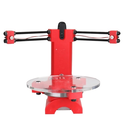 .. While studying the forum of this program, I often came across various schemes of turntables - fortunately, the software allows you to automate the scanning process. After one scan, a command is sent to the com port, the turntable rotates, turning the object by a given number of degrees, and gives a command to the next scan. As a result, with one click of the mouse, we have circular scans of the object - it would seem, what more could you want? I tried this system with interest, but alas, I absolutely did not like this approach, and there are a couple of reasons for this. nine0003
1 – if the object has a complex shape, then simply rotating it will not be enough – you also need to tilt it in different directions so that the camera with the projector reaches all the depressions and other hard-to-reach places.
2 - even if there are no such places, and considering all the scans that were made, there are no parts left on the object that did not fall into the scan, the question of the accuracy of the scan remains.
Let's say that some part of the model on one of the scans came out perfectly. But this does not mean that on all the scans in which this part fell, it also looks perfect, and when stitching scans from different angles, the result will be averaged, which cannot please. The program allows you to slightly edit the received scans (you can cut out the unnecessary part). If we rotate the model by 20 degrees, then after a full rotation we will have 18 scans, the part we need may well be present on half of them, therefore, in order to leave the best result, we will need to remove this piece from 8 scans ... And such pieces with a complex There can be many models, as a result, almost half will be cut off from each scan, which is very laborious and time consuming. nine0003
Instead, it is better to immediately scan adjacent areas after the first scan and check the result. As soon as a piece is ready, we move on to scanning the next one, and so on, until the entire model is in perfect shape. This approach gives the best results in less time.
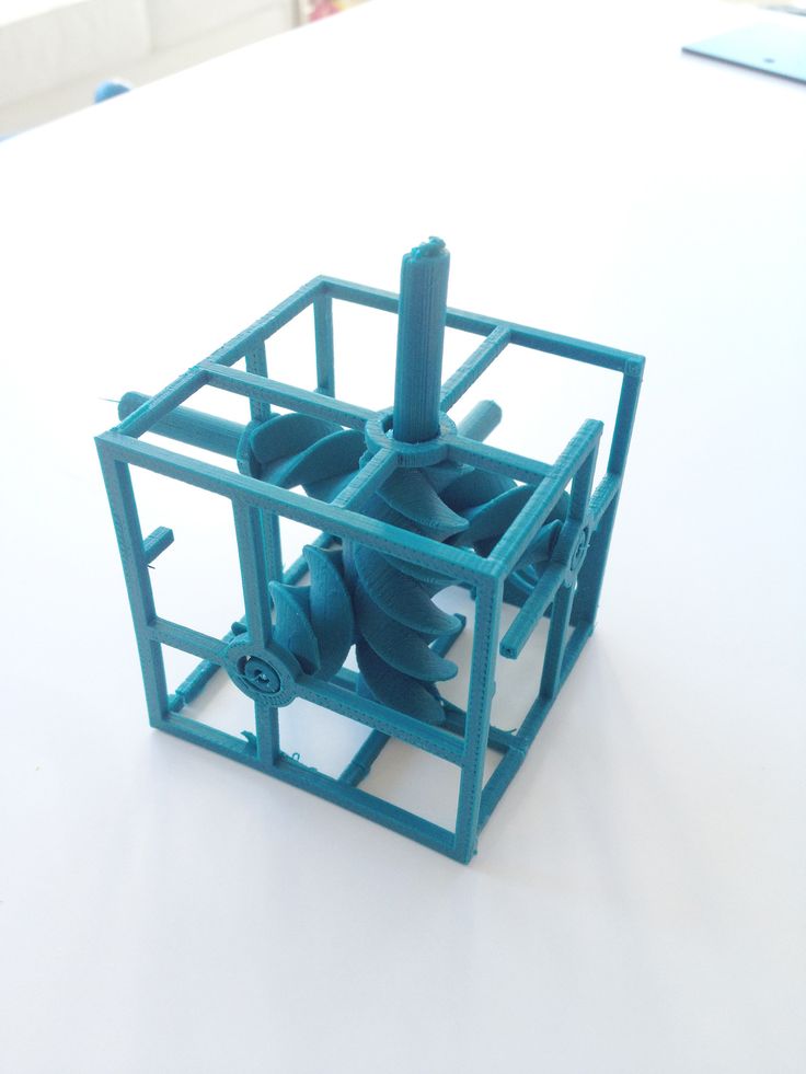
But the question of convenience arises. Agree, it’s inconvenient to manually try to rotate an object, looking not at it, but at the monitor - in order to control the hit on the lens without changing the distance to the camera and the projector at the same time (so as not to lose focus). With the next similar balancing act, I accidentally touched the camera, which accordingly knocked down the entire calibration, and the whole process had to be started anew. I categorically did not like this alignment, and after some thought I came up with a plan for such a design (which, as you understand, I subsequently assembled). nine0003
This is not a turntable in the usual sense of the term. Thanks to this design, I can not only rotate the model, but also tilt it as I need. In this case, the center of the model remains in the plane of focus, but even if not, you can move the mount with the model back and forth.
All this was assembled on arduino, a small control program was written, and as a result, now I don’t have to get up from the computer when scanning - using the program, I change the position of the object being scanned, and at the same time, right there, in the window cameras I choose the best angle for scanning. nine0003
Insides
I put the possibility of automatic scanning into the program, as well as scanning not only in a circle, but with inclinations of 45 degrees in one direction and the other, which gives three times more scans. Nevertheless, in the end, I still never use this opportunity - it's too inconvenient to sort through the resulting pile of scans and clean them from unsuccessful pieces.
We should also mention some nuances of scanning.
1 - it is impossible to scan shiny and mirror surfaces. The light from them is reflected, or gives such a glare that the program cannot correctly recognize the line. If there is a need to scan such an object, then such parts will have to be masked with something (washable paint, paper tape, etc.). nine0005 2 - it is more convenient to scan monotonous objects, since when the camera is set to a light color, the projector's brightness is not so high, the exposure is low, etc. And a dark-colored object needs more brightness, so if you have a multi-colored object, then different parts of it require different settings to get the best result. Here, too, it is more convenient to use scanning the object in parts.
3 - if you want to immediately get a color texture, then please note that the settings of the camera and the projector for scanning do not affect the settings for removing the texture (the scan is generally done in black and white mode), so play around with the settings in the texture mode just as you would do in scan mode. nine0003
My scanning process now looks like this:
- Focusing the projector and camera
The projector's light is too bright and the projected grid is not visible in the photo, but here is the view from the camera in the program
- scanner calibration
printed on magnetic paper - so you can very quickly adjust to different sizes of scanned objects. nine0003
Software view
It is recommended that the combined angle between the beam of the projector and the camera be around 20 degrees. Therefore, such a stand is used - when scanning large objects (for example, a person), the camera should be set aside much further from the projector, but here they are close to me. The location of the camera relative to the projector can be only vertical, or only horizontal, depending on the geometry of the object. In this case, the arrangement is diagonal (13 degrees vertically and 36 degrees horizontally). nine0003
Scan results from different angles. These are already cleaned up scans, i.e. all unsuccessful and unnecessary parts (figure stand, mount that got into the frame) parts have been removed.
Combining scans for subsequent merging into one object
Due to the fact that each scan has its own color, it is convenient to control the correct alignment.
Well, after combining the scans from different angles, we get the following models
Miniature of Boromir from Lord of the Rings. nine0005
When scanning a multi-colored object, the result is slightly worse if you don't bother too much. But then you can get an object with a texture right away :) , even fingerprints people scan. And there are even scans of the same miniatures from Warhammer
In conclusion, I would like to say that no matter what hardware you use, no matter what expensive 3D scanner you buy, this is not a panacea for printing anything. Theoretically, of course, you can send the resulting object to the slicer and print, but there are several reasons why you should not do this, but in any case, you should study 3D graphics packages. nine0003
1 - The resulting scans, with good scan quality (and we want to get the best quality) have a lot of polygons. No, even is VERY a lot. The scan of Boromir after the merger contained more than 8 million polygons - not every slicer will be able to work with such an object.
2 - Any objects bear traces of assembly and manufacture. And if in reality needle files and sandpaper are used to fix this (and sometimes there are still inaccessible places where it is impossible to use tools), then working with a digital copy of an object, we can change it as we like - remove defects, improve detail, etc. . nine0005 3 - As I said at the beginning of the article, when I thought about the scanner, I did not want to print copies of objects, but change them as I please. I am not a sculptor, I do not have the tools, materials and skills to sculpt such a small model.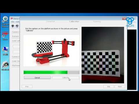 But knowing how to work in 3D, it is much easier for me to scan a similar Boromir and make him some kind of Prince of Denmark.
By the way, this model already contains almost 100 times fewer polygons than the scan result.
EinScan HX-SHINING 3D handheld 3D scanner overview
Shining 3D, a Chinese manufacturer of 3D digitizing and additive manufacturing equipment, introduced the EinScan HX handheld 3D scanner in 2020. In the 3D digital copying market, Shining 3D's scanner outperforms competitors in terms of price and quality, and in some ways even surpasses them. Take a look at Shining 3D's Einscan HX 3D Scanner review and learn about its features, capabilities and use cases.
EinScan HX
at a glance EinScan HX In 2020, Shining 3D engineers announced the EinScan HX handheld scanner with industrial design capabilities. By combining hybrid and laser light, it has been possible to realize 3D scanning in various applications, and the accuracy reaches 0.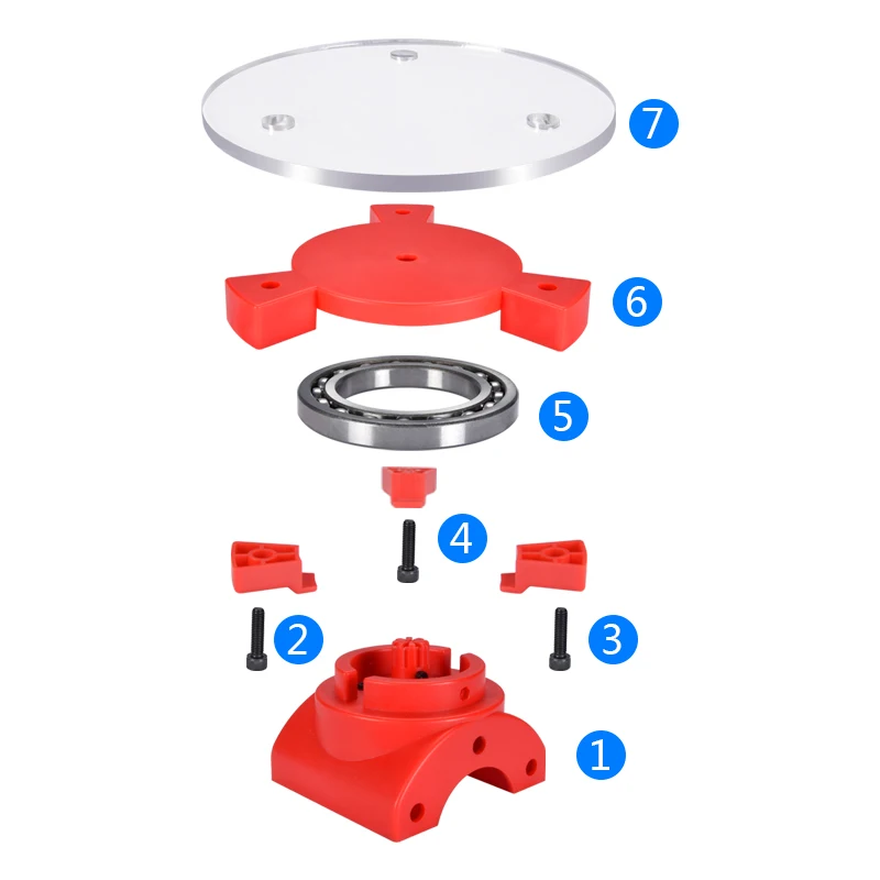 04mm.
04mm.
A compact hand-held device weighing only 710 g makes it possible to obtain a digital 3D copy of large objects - parts and body elements of cars, structural elements of aircraft, small architectural forms, sculptures, pieces of furniture. nine0003
Large area scanning of black, shiny, and glare surfaces is available. Such characteristics are inherent in expensive professional equipment for 3D digitization.
Appearance EinScan HX
EinScan HX 3D scanner is a hand-held portable device, which consists of two emitters connected by a handle: upper and lower. At the top is a laser, and at the bottom is an LED structured light source. The scanner is comfortable to hold in your hand thanks to its ergonomic handle design and light weight of only 710g. nine0003
Contents
- Scanner.
- Markers.
- Power adapter.
- Calibration board.
- Position paper.
- Connecting cable.
- USB stick.
- Plugs.
A special plastic case with compartments is provided for storing and transporting the device and accessories.
Scanning modes
The EinScan HX scanner has two scanning technologies: structural blue LED illumination (the left side of the device is responsible for it) and triangulation, or laser scanning. nine0003
An LED backlight is a grid projected onto an object, along which the software builds a digital image with an accuracy of 0.05 mm. Scanning can be done by detail, texture and markers. The laser beam creates seven crosshairs instead of a grid. The scanning process is carried out only by markers, the accuracy is 0.04 mm.
The shift of the zero point as you move away from it is 0.1 mm per 1 m in the structure illumination mode and 0.06 mm per 1 m when scanning with triangulation technology. This parameter is called volumetric precision .
Scanning modes EinScan HxFeatures:
- ease and convenience of use;
- high scanning speed in the structure illumination mode;
- performing a seamless scan;
- In laser scanning mode, the speed is lower, but most objects for reverse engineering, CAD / CAM, 3D printing, etc.
 are digitized.
EinScan HX specifications
0268
| ,05+0.1 mm/m | 0.04+0.06 mm/m | |
| Scan and alignment speed | 1,200,000 dots/s, 20 fps | 55 fps |
| No |
Computer Requirements
The 3D scanner is connected to a PC in Plug & Play mode. Special requirements are imposed on the characteristics of the computer:
- large amount of RAM - at least 8 GB, but 32 GB is recommended;
- Nvidia 4 GB video card - the scanner does not work correctly with AMD video cards;
- Hi-Speed USB 3.0.
3D applications must be installed on the PC. Shining 3D provides its own Geomagic Essentials SHINING 3D Edition software for exporting files to CAD applications.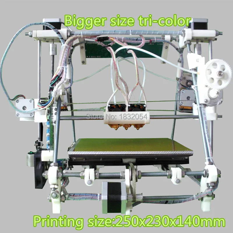 Users note the functionality of the software, usability and intuitive interface. The software bundle also includes the Solid Edge SHINING 3D Edition 3D design suite. nine0003
EinScan HX CAD/CAM software
Applications were developed by Shining 3D IT specialists in tandem with SIEMENS PLM Software and 3D Systems, the world's leading providers of software solutions for professional 3D scanning, 3D design, control functions, reverse engineering and additive manufacturing for enterprises of numerous industrial sectors.
Solid Edge SHINING 3D Edition
The Solid Edge SHINING 3D Edition platform is a complete solution for reverse engineering, design and simulation. The programs provide integration with CAD tools. nine0003
Solid Edge SHINING 3D Edition allows you to create high-quality three-dimensional models for further use in industrial production according to the algorithm: digitization - design - modeling - additive manufacturing.
Geomagic® Essentials™
3D Systems and SHINING 3D programmers have collaborated to create a suite of software applications, a versatile package for working with digital objects.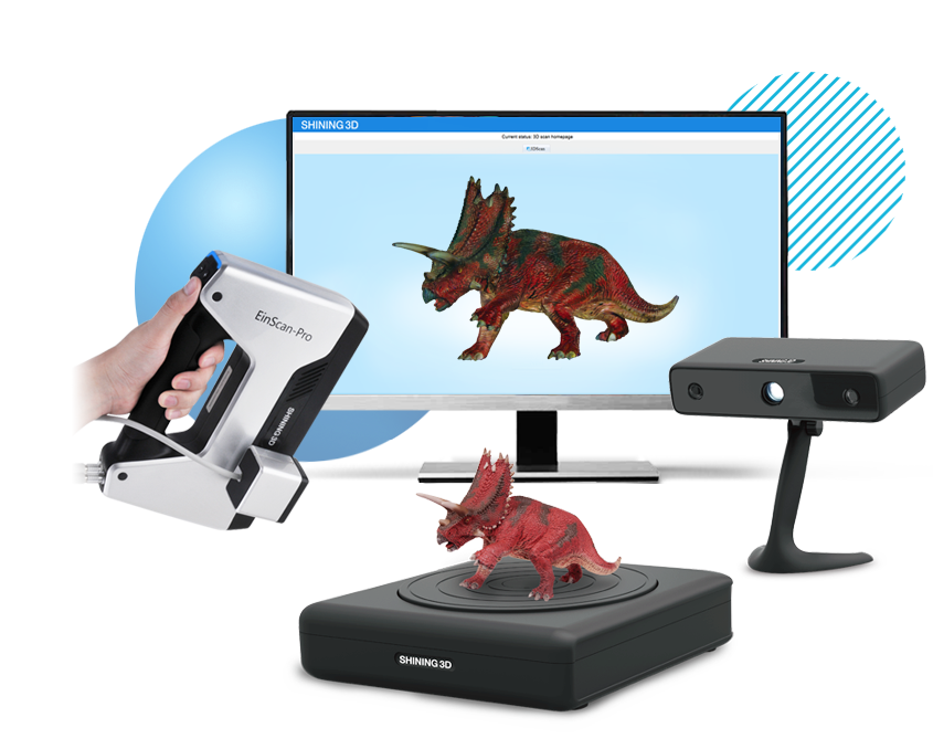 Converting 3D scans to CAD is always a challenge. Geomagic Essentials is a set of tools to extract all the necessary elements for export to custom CAD software. nine0003
Examples of 3D scans obtained after scanning objects with EinScan HX
A 3D scanner developed by Shining 3D specialists is able to digitize a three-dimensional object of any size and shape, including advanced complexity:
Air compressorWheel rimBicycle helmetCases: EinScan HX
3D Scanner Applications and Functions Special Vehicle Equipment
Scanning EinScan HX Commercial vehicle manufacturer System Strobel specializes in medical vehicle equipment. Alteration of standard models is associated with the complexity of calculating the parameters of the equipment that needs to be installed in the cabin. Scanning the vehicle body and components using the EinScan HX scanner makes it possible to obtain a digital copy of the reworked assembly. Designers and 3D designers start working on it, quickly getting the final result - a three-dimensional model of a structural element.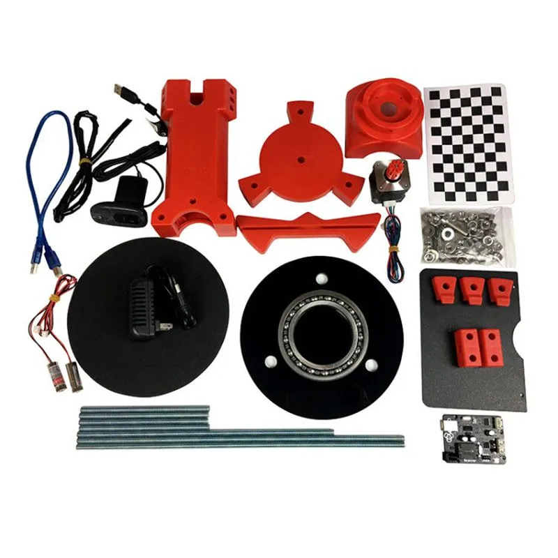 All parts, including complex shapes, are manufactured with high precision and high speed. nine0003
Read more about the case EinScan HX ideal for emergencies
Mining equipment
Darkhangeomach manufactures mining and heavy industry equipment, including tools and spare parts. To create complex polygonal surfaces for reverse engineering, designers were looking for an effective solution. 3D scanners have won in comparison with coordinate measuring machines. The EinScan HX 3D scanner was chosen as the scanning device. nine0003
So, a laser module was suitable for scanning the impeller, which allows processing shiny metal surfaces. The part scan was exported to Geomagic Essentials software for further processing. The image was then sent to Solid Edge SHINING 3D Edition, where the design of shapes and parts was completed with high precision. The use of Shining 3D products has simplified the task of manufacturing the necessary structural elements.
Read more about the case - Aiming for success with "EinScan HX".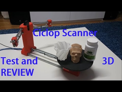 nine0003
Manufacture of motorcycle parts
It can be difficult and expensive to replace a component, due to the fact that motorcycle manufacturers do not sell some individual parts, but sell the assembly. To make a part, you need to design it and then cast it from metal or plastic. If a component is copied from a digital 3D model and then printed on a 3D printer, it will take less time and require less investment.
EinScan HX was selected for 3D scanning. The digitized part is processed in a software application in order to obtain an STL file, from which the code for additive printing of the object is created. The introduction of the technology made it possible not only to obtain the necessary spare parts, but also to optimize their weight and shape to improve functionality. nine0003
Read more about the case study - Customizing a motorcycle with SHINING 3D's scan-design-print workflow.
Mesh Optimization
The EinScan HX scanner firmware has been updated with the mesh editing and optimization function. The operation involves several options: smoothing, sharpening, which helps to eliminate surface noise and maintain image clarity. The user has access to the intensity in the range from 0 to 100% and the possibility of several iterations. nine0003
Read the Mesh Optimization Instructions
Testing 3D Scanner Accuracy
Scanner accuracy refers to the accuracy of a single measurement and volumetric accuracy, that is, the accuracy of a volumetric image already aligned and assembled into a complete data set. The EinScan HX 3D scanner was tested to meet the accuracy parameters when a reference object is scanned and the results obtained are compared with standards. The measurement is performed in the Geomagic Control X software. According to the results of the test, the accuracy of the Shining 3D scanner falls within the range specified by the standards. nine0003
Read the article - EinScan HX handheld 3D scanner accuracy
Efficient measurement of large objects
The existing technique for measuring 3D parts involves the use of a hand tool - a micrometer and a caliper.