3D scanner engineering
3D scanners for reverse engineering — best Artec 3D scanning solutions
Applications
HD meshes for CAD workflows
Confidently and easily capture data from existing parts with the assurance of ultra-high precision and accuracy.
Rapid prototyping
With tools that seamlessly integrate into your existing workflow, you can quickly and easily prototype, test, and get insightful feedback on design solutions.
Retrofitting
Redesigning parts that are no longer in production has never been easier, with none of the errors, inconsistencies, and time demands that come with taking measurements manually.
Aftermarket parts production
With reliable 3D scan datasets, paired with Artec Studio’s versatility, you have the ability to develop high-quality aftermarket parts.
Additive manufacturing
You can take advantage of the flexibility that 3D printing brings to quickly actualize and test reverse-engineered designs.
A leading developer of high-performance chassis saves days of work by using Artec Eva, Artec Studio, and Geomagic Design X to engineer custom solutions for racing.
7x
reduction in time spent capturing and processing scans.
“Eva has been such a game-changer. Now I’ll take a bunch of parts and scan them in before lunch. By the end of the day, we’ve done all our analysis, everything is on schedule to create the final design.”
Jason Heard, Co-founder, Tekk Consulting Inc.
Read full story
In the media
Royal Netherlands Navy 3D scans their ships using handheld Artec 3D scannersTHE VERGE
Classic Land Rover goes electric with the help of Artec LeoTop Speed
3D scanning ensures cameras will mount to helicoptersMake Parts Fast
User-friendly portable 3D scanner with an inbuilt touchscreen and intuitive UI for easy 3D scanning.
Learn more
Our bestselling 3D scanner. Fast, versatile, and accurate.
Learn more
A metrological structured-light 3D scanner, set apart with its ability to render complex geometry, sharp edges, and thin ribs in high precision.
Learn more
Powerful long-range laser 3D scanner with an inbuilt battery, for precise capture of large objects.
Learn more
Metrology-grade desktop 3D scanner for quality control, inspection, jewelry, medical/dental components, etc.
Learn more
Using Artec 3D scanning technology to keep Dutch Royal Navy ships seaworthy
“We are now able to work a lot faster and more accurately. Because we now have a complete 3D model, we have all the correct dimensions of every object. It results in a far more efficient way of working and it is faster, so we save a lot of money in these projects.”
Ben Jansen, CNC coordinator at the Netherlands Defense Ministry
Read full story
Reverse engineering huge machine parts in difficult locations with Artec Eva and Geomagic Design X
“Artec Eva was the suitable scanner for this job as the parts were very big and the accuracy required was in the range of Artec Eva’s accuracy.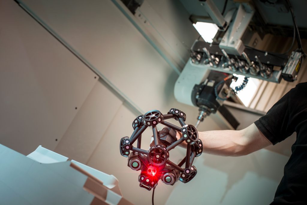 The scanning was pretty fast and easy considering that those were huge parts, around 3 meters…No other scanner can measure such big parts this accurately and fast.”
Ali Can Boysan, Teknodizayn Sales & Technical Support Manager
Read full story
Putting Claws on the Black Panther Lexus with Artec Eva at West Coast Customs
“It's a huge help that Eva is lightweight and comfortable to hold, which makes scanning actually fun to do … you don’t need to use it for long before you look over at the laptop and realize that you’ve scanned the whole car … it either would’ve been just impossible without Eva or much more difficult and definitely not as precise.”
Lorenzo Strong, West Coast Customs Sales VP
Read full story
Slashing weeks off reverse engineering farm equipment with Artec Eva
“Eva has literally saved us days if not weeks of work, and that’s no exaggeration. Previously we were spending all that time creating prototypes to test, then that many more hours on alterations to reach the level of perfect, compared to now achieving perfection the first time, and every time, with Eva.”
Mark Taylor, Taylor Attachments
Read full story
User-friendly portable 3D scanner with an inbuilt touchscreen and intuitive UI for easy 3D scanning.
Learn more
Our bestselling 3D scanner. Fast, versatile, and accurate.
Learn more
A metrological structured-light 3D scanner, set apart with its ability to render complex geometry, sharp edges, and thin ribs in high precision.
Learn more
Powerful long-range laser 3D scanner with an inbuilt battery, for precise capture of large objects.
Learn more
Metrology-grade desktop 3D scanner for quality control, inspection, jewelry, medical/dental components, etc.
Learn more
Complex motorcycle engine captured by Artec Leo in just 8 minutes
Artec Leo
Pipe bend captured with Artec Micro in only two scans over four minutes
Artec Micro
Motorcycle crankcase captured by Artec Space Spider in 15 minutes
Artec Space Spider
Compound bow captured by Artec Eva in just five minutes
Artec Eva
Artec Ray was used to scan an airplane suspended three meters high.
Artec Ray
How to Use 3D Scanning and 3D Printing for Reverse Engineering
Reverse engineering is a powerful way to create digital designs from a physical part, and can be a valuable tool in your prototyping toolkit alongside technologies like 3D scanning and 3D printing.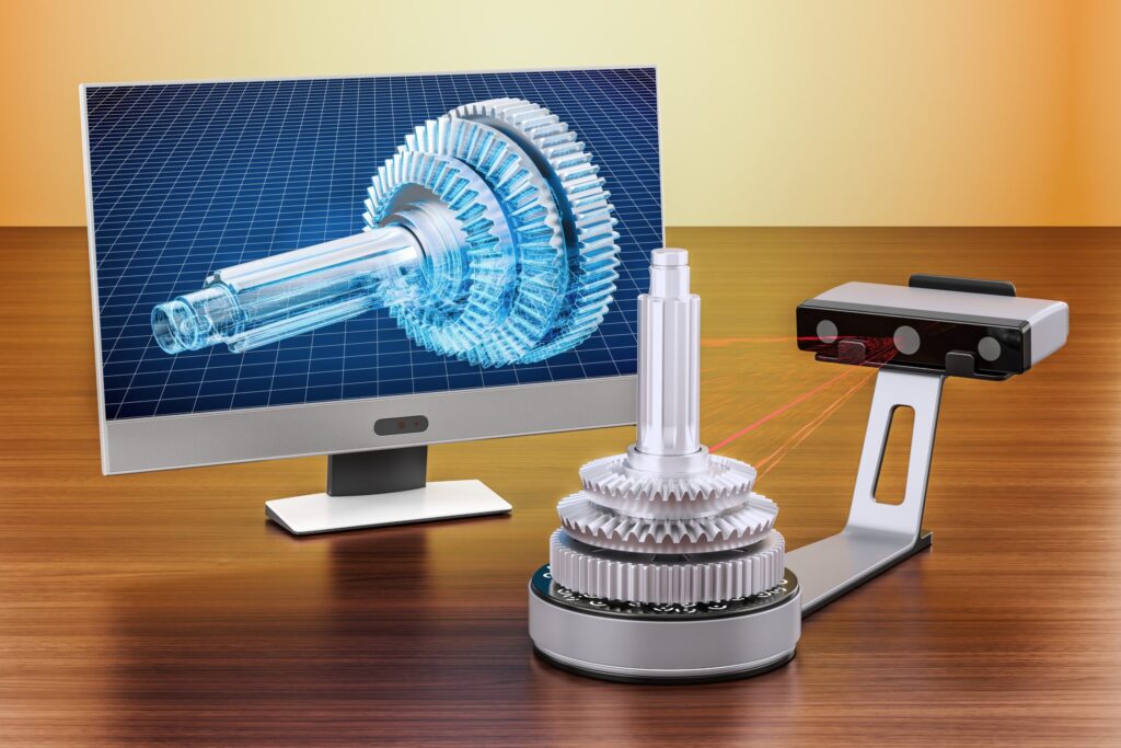
3D scanners measure complex objects very quickly, and can speed up your design workflow tremendously when real-life references are involved. With the ability to capture and modify physical shapes, you can design 3D printed parts that fit perfectly on existing products of all kinds. 3D printed jigs allow you to repeatedly locate a drill or saw, or assemble parts precisely with adhesive. Create close-fitting, reusable masks for sandblasting, painting, or etching.
In this post, we’ll walk through the step-by-step reverse engineering process for an aftermarket digital gauge and explain how to scan a part for 3D printing, with tips along the way for using the right reverse engineering tools, from CAD software to to 3D scanners and 3D printers.
For a full breakdown of 3D scanning workflows and technologies, download our white paper.
Download the White Paper
Looking for a 3D scanner for your 3D printer? Read our detailed guide on choosing the best 3D scanner to use with your 3D printer.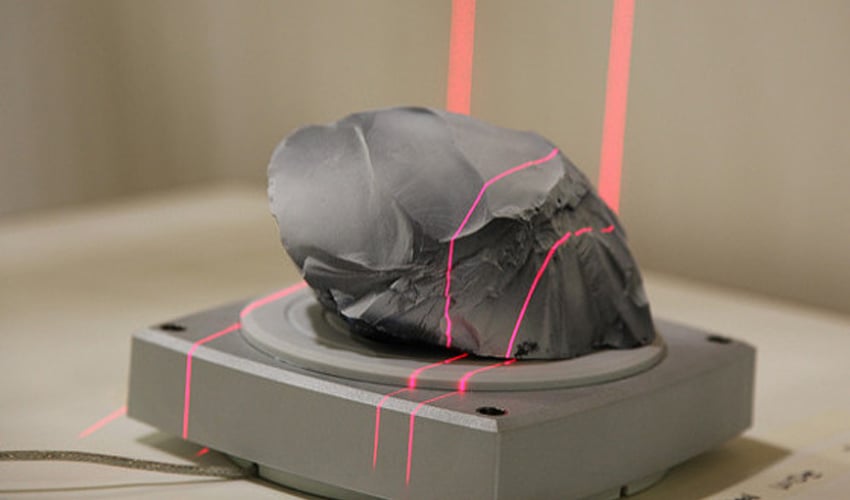
One of the biggest challenges people encounter when converting physical objects to digital is a major incompatibility between two different types of 3D models: meshes and solids.
A 3D scanner outputs a mesh, rather than a constructive “solid” model. Meshes need to be reverse engineered to be made editable.
Meshes are the main output of all 3D scanners, and the format commonly understood by 3D printers (STLs). A mesh represents the surface of a shape with a large number of triangles, connected edge to edge. Mesh models don’t contain any information about the object, besides the position of the triangles that define the shape.
On the other hand, engineers are trained to work with solid models. Solid models hold information about how an object is designed, and this information is explicitly encoded into the model as features in a ‘stack’ of logical steps. In solid CAD, it’s possible to change the dimensions for a single feature, and the rest of the model will update to accommodate the change.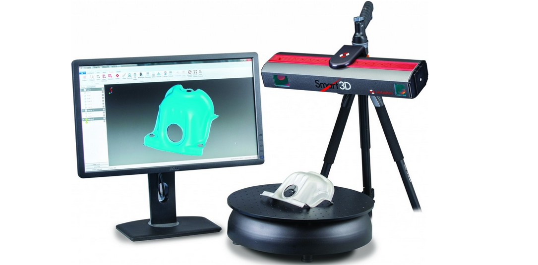
Since meshes lack information about the construction of the object, the ways you can alter a mesh model are limited—CAD software like Solidworks and Onshape can’t directly modify meshes. If you need to make major modifications to the underlying design of a scanned part, the mesh needs to be converted to a solid CAD drawing: this process is reverse engineering.
Reverse engineering is important when you want to create new parts that reference or incorporate older designs, where the original CAD design isn’t accessible.
For example, you can create replacement parts that match the original design of damaged existing pieces, or use reverse engineering processes to integrate complex surfaces from existing objects into 3D printable jigs, which are useful when modifying mass manufactured and handcrafted products.
To demonstrate the basic steps in a reverse engineering workflow, let's take a look at the process for creating an assembly jig for an aftermarket digital gauge that fits onto the air vent of a Volkswagen Golf.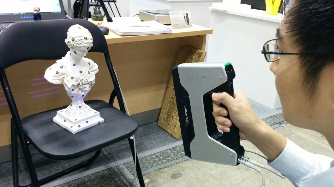
Spray coat the object with a temporary matte powder to improve scan accuracy. Even slightly glossy surfaces tend to degrade scan quality, while reflective and transparent surfaces cannot be scanned at all without a matte coating.
Use a temporary matte powder to improve the scan accuracy of your object.
Use a high accuracy 3D scanner to capture the important sections of the part. Tabletop structure light or laser scanners are the right tools for the job, with accuracy of ±100 or better.
Learn more about how to choose the right 3D scanner for your application in our 3D scanning white paper:
Note: You may need to orient and re-scan your object several times if the object has deep recesses.
Some scanners produce extremely large mesh files, which will make later steps grind to a halt.
Scanner software repairs small gaps and simplifies the scan, making the data more manageable in CAD. Try to reduce the model as much as possible without destroying important details.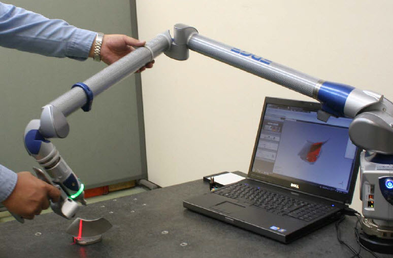
Tip: If you need more control, Meshmixer is a great choice for refining scanned meshes.
Import the mesh into CAD software equipped with reverse engineering tools. Geomagic for Solidworks is a powerful choice for resurfacing complex, organic shapes.
If you are reverse engineering a part with simpler flat surfaces, Xtract3D is a less expensive, lightweight alternative.
In this step, move and rotate the scan mesh into alignment with any existing design components.
Tip: Make drawing easier by rotating and aligning your scan to face the orthographic view directions.
There are three paths to extract the shape of the scan in order to create a solid model that is editable with CAD tools: semi-automatic surfacing, automatic surfacing, and manual redrawing.
Semi-automatic surfacing
Complex curved surfaces are difficult to manually draw, so you may choose to use semi-automatic surfacing. This function generates surfaces that fit to detected regions of the scan. By varying the sensitivity of the surface detection function, different surfaces will be found.
Tip: Geomagic for Solidworks detects surfaces on the scan to fit 3D curves. Use a “brush” to manually add or subtract areas on the scan from each region.
You may need to repeat this process several times with different sensitivity settings to detect all your surfaces. These surfaces can then be trimmed and knit together to create an editable solid.
Use semi-automatic surfacing to re-create curved shapes when you want maximum editability later on, and when sharp edge accuracy is important.
The re-surfaced result, after trimming.
Automatic surfacing generates a solid model from any watertight scan. You can use standard CAD tools to subtract and add to this auto-surfaced body, but it will be more difficult to move basic features around on the body itself.
You may not need control over edge placement. For example, if you are scanning a part of the human body to create custom ergonomically-shaped products, or want to create a jig to precisely or repeatably modify a handmade object. In these cases, automatic surfacing is a great way to save modeling time.
Note: Compare the results of a automatic surfacing to semi-automatic surfacing: some accuracy is lost, especially around sharp edges.
For simple features such as bosses, holes, and pockets, it’s usually fastest and most accurate to redraw the features using the scan model as a reference. Reverse engineering software allows you to create sketch planes aligned with flat surfaces on the scan and to extract cross sections from the scan mesh, which helps you match the shape of the original object.
Once the scan has been converted to a solid, it can be subtracted from another solid body to create a jig that securely holds the original part.
The design of the new gauge component also references the dimensions of the scan, using curves extracted with semi-automatic surfacing.
Printing the jig on a Formlabs stereolithography (SLA) 3D printer gives you a high degree of accuracy comparable to the output of engineering-grade 3D scanners.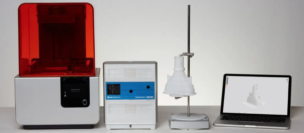 Use Formlabs Rigid 4000 Resin for its strength and precision.
Once these steps are complete, the 3D printed jig is ready to use to assemble the new gauge onto the OEM air vent.
The final 3D printed assembly jig, printed in Rigid 4000 Resin.
DSTU developed a high-precision 3D scanner for analyzing the patient's stump to create a comfortable and functional prosthesis socket
DSTU developed a high-precision 3D scanner for analyzing the patient's stump to create a comfortable and functional prosthesis socket high-precision scanning of a truncated upper limb when creating a prosthesis. BioSculptor 3D Touch Scanner automatically examines the stump, collects information about the location of muscles, bones, adipose tissue and creates a 3D model of the stump sleeve. nine0003
On average, 63.4% of patients refuse a prosthetic hand due to technical limitations and the appearance of the device, the discomfort it causes, and most importantly, due to a lack of awareness of options for solving these problems.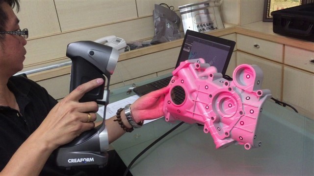 With all the technological and functional diversity of solutions, the main drawback of any of them is the sleeve that is put on the limb.
The BioSculptor 3D Touch Scanner automated stump analyzer is designed to improve the quality of manufacturing a prosthesis stump and reduce the cost of its development. The device will simplify the work of prosthetists, increase the accuracy of designing prosthesis sleeves, and in the future will increase the information content of EMG studies. nine0003
– The sleeve is one of the most important individual components of the prosthesis, it connects the truncated limb with the mechanical modules of the prosthesis and perceives the main static and dynamic loads. The problem of creating comfortable and high-quality sleeves remains one of the main problems in prosthetics. The shape and material of the sleeve largely determines how the connected technical device will function, and ultimately the comfort of the patient wearing the prosthesis, - said Denis Khashev, a postgraduate student of the DSTU, the developer of the Robotics profile of the Institute of Advanced Technologies "School X".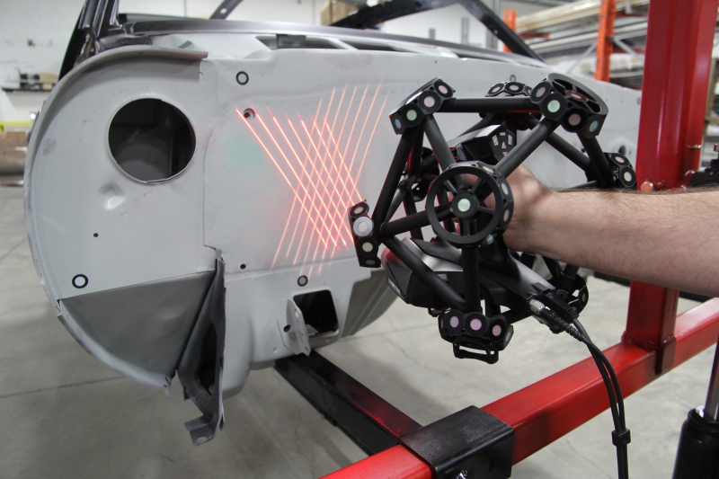 – BioSculptor 3D Touch Scanner is a unique device that has no analogues in the world. For example, the MIT Media Lab has a development designed only for the lower extremities. Our device analyzes the stumps of the upper limbs. In addition, the BioSculptor 3D Touch Scanner is smaller and takes up to 15 minutes to analyze. nine0003
The procedure is fully automated. BioSculptor 3D Touch Scanner scans the shape of the stump, analyzes the location of muscle, bone and adipose tissue using strain gauges and touch sensors. For analysis, the patient needs to place the stump in the center of the measuring ring, the analyzer moves along the limb, exerting pressure on the surface of the stump and reading data every centimeter. Exceeding the limit force is monitored using a sensitive strain gauge, the procedure is painless for the patient. The data in the form of a point cloud is transmitted to the operator on the computer, then the program builds a 3D model of the patient's stump and sleeve. The output of the scan result in the form of a 3D model allows you to quickly and effortlessly explore the measurement results. The study of the stump lasts no more than 15 minutes, the construction of a 3D model takes 30-40 minutes. nine0003
BioSculptor 3D Touch Scanner was presented at the international festival Ot Vinta!, which takes place from March 25 to 27 in Krasnodar.
A limb stump is a part of a limb or its segment left after amputation, trauma, or formed as a result of congenital underdevelopment.
The receiving sleeve is an individual module of the prosthesis. As part of the prosthesis, the receiving sleeve connects the truncated limb with mechanical modules and perceives the main static and dynamic loads in the "man-prosthesis" system. The main functions of the sleeve include: placement of the stump, pairing and retention of the prosthesis on the truncated limb, support, transmission of movements and controllability of the prosthesis during movement.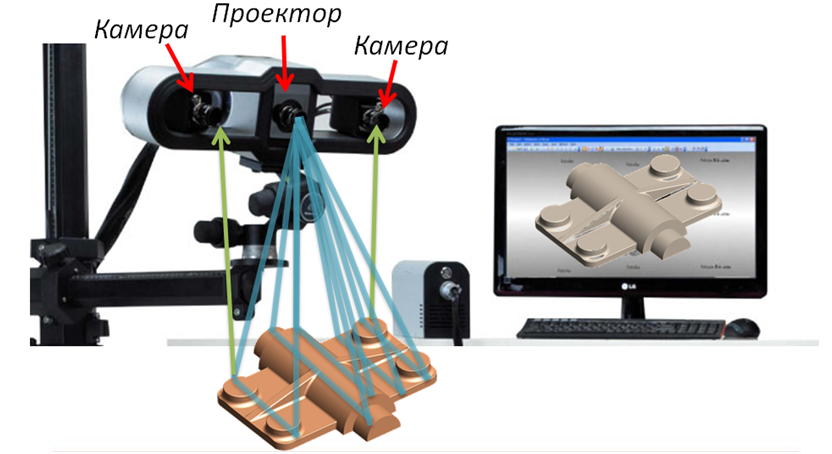 nine0003
3D scanning as a turnkey solution for the mold industry
How do you define your requirements for 3D scanning as a mold maker?
How to implement 3D scanning in mold production?
Due to the rapid development and tremendous technological progress in all industries over the past decade, the structural design of products has become more and more complex, and an unprecedented number of mold contours have appeared. With the increasing proportion of free-form surfaces and the increasing demands on the accuracy of mold processing, producing high quality molds and ensuring consistency and quality in the production process has become a decisive factor for manufacturers. 3D scanning technologies have radically changed these processes. But how do these technologies actually improve the mold making and processing workflow, and what examples show how this technology can be put into practice? What are the main benefits and how can I get started with 3D scanning easily and uncomplicated? These are some of the questions we will delve into. nine0003
Mold design with 3D scanning and reverse engineering
Reverse engineering refers to the process of extracting design elements from an existing finished system or product, primarily manufactured in an industrial way, by studying its structures, states and behavior. Basically, an accurate technical plan is created based on the collected data about the object. Unlike functional recreation, reverse engineering seeks to reproduce an existing object as accurately as possible. To test the understanding gained, an attempt is often made to create a 1:1 copy of the object from which further development can be carried out. The attitude towards reverse engineering in any industry is very ambiguous. But the possibilities it opens up for mass customization and product design, especially in the mold industry, are undeniable. nine0003 Reverse engineering workflow
Create mold CAD data by 3D scanning the part
The first step of digitizing in casting is to 3D scan the tooling part. Professional and inexpensive digitization of components has become possible for everyone with little effort and with the help of a 3D scanner. 3D data can be easily acquired in situ, and users benefit from very short uptime, low cost, efficient use, and easy interaction. nine0015
Processing 3D scan data into CAD data
The second step in creating digital molding tools is to convert the point cloud created in 3D scan into CAD/CAM capable data. The processing of STL data obtained with a 3D scanner can then be reconstructed in CAD. Part characteristics can be recognized by scan points, and these points can be replaced with CAD-enabled surfaces. This process is called surface reconstruction. With the CAD/CAM solid model data ready, tooling molding can begin immediately. nine0003
Mold measurement with 3D control
Traditional form measurement methods are usually performed manually using contact measuring tools such as vernier measuring tools or micrometers. Only some parameters can be measured, such as the width, height, and depth of a form, while the curvature of surfaces and recessed surfaces is difficult to measure. These measurement methods are not only complicated and time consuming, but it is also difficult to ensure the measurement quality and accuracy of large-sized molds, which makes mold measurement a very time-consuming and labor-intensive part of industrial production. nine0003 Traditional measuring instruments.
Image Source: Baidu
For this reason, non-contact measurement with a 3D scanner is gradually becoming one of the main methods for measuring industrial molds due to its ability to overcome the shortcomings of traditional measurement methods and provide high-quality control, which is vital to ensure trouble-free production in the long term. perspective. quality identical molded products.
There is a wide range of 3D inspection tools based on different scanning technologies to meet different inspection requirements.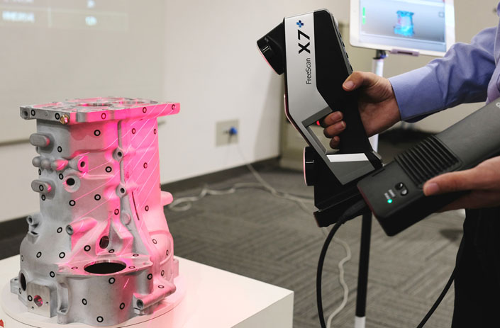 This article takes a look at several projects using different technologies to showcase the wide range of applications these devices can be used for.
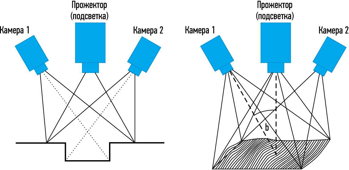
Blue Light Metrology 3D High Precision Inspection
"Blue light technology recognizes a contour by triangulating the line of sight of a photographic lens and the line of sight of a light source, which projects a pattern of 'streaks' onto the surface being measured, and then uses software to convert multiple images into 3D view"
– K.R. Srinivas , Qualitymag.com
Learn more
Blue Light Metrology 3D scanning technology is capable of accurately capturing the fine and filigree details of tiny to medium objects that require consistent performance throughout the product's lifecycle.
Checking nuts with OptimScan 5M
Nuts are an essential part of everyday life. For all kinds of products and fixtures, strong and stable nuts are required.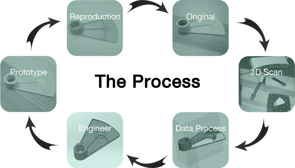 Usually the nuts are poured and then processed to the final product. The performance of a cast nut directly affects the performance of the nut and the bold assembly, which is vital to the reliability, strength, and stability of the installation or product it is screwed into. Therefore, quality control of the molds used for casting nuts is essential to maintain the high quality and safety of the product. Blue light 3D scanning technology can greatly help in checking the dimensions of the nut assembly and thus ensure accurate mold maintenance. nine0003 Mold for nuts
Measurement requirements:
Measurement of the main dimensions according to the drawing. The pitch directly affects the compatibility of the bolt and nut. The half angle (angle of 15°) of the threaded sickle will affect the fit of the nut and bolt tooth pattern, and the consistency of tooth profile flatness will affect the degree of surface engagement of the bolt and nut, i.e. stretch or not.
Conventional measurement methods are inconvenient due to the helical arrangement of the teeth.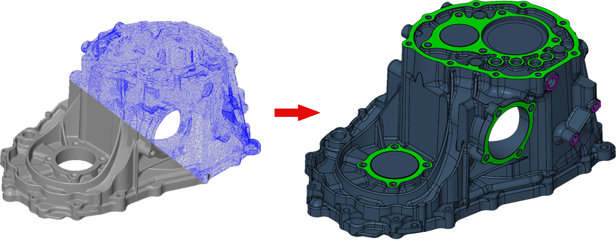 It takes half a day to measure one product, which is obviously extremely inefficient. nine0015
Recommended Meter:
OptimScan 5M Blue Light Metrology 3D Scanner
Nut 3D data is captured by OptimScan 5M and then imported into the measurement software. The advantage of such software lies in the freedom of measurement. There are no shape restrictions, and cross sections can be easily measured after 3D data is collected. Let's look at the measurement process:
1) Acquisition of 3D point cloud data by 3D scanning
2) Data import into measurement software and coordinate matching
3) Pitch and profile measurement by creating a 2D cross section; measurement of the inner diameter of the nut. and flatness of the profile by creating cylindrical elements and planes.
 D. Measurement, screw flatness measurement
The measurement accuracy of the OptimScan 5M can be up to 0.01 mm, which guarantees very accurate measurement results. Thanks to the high efficiency of modern technology, scanning and measurement can be completed within one hour.
Full 3D inspection of automotive lamp housings with OptimScan 5M
Measurement requirement: Full 3D inspection of automotive lamp housings. nine0003
The deviation caused by processing is not only a human factor, but also caused by temperature and humidity, which greatly affect the accuracy of the product; out-of-tolerance size affects the assembly of lights and related parts, and out-of-tolerance parts found must be corrected as required to meet assembly requirements. Thus, the key step in product quality control is to carry out three-dimensional full measurements of the workpiece. nine0003
Traditional inspection methods: traditional inspection with calipers, micrometers and coordinate equipment to establish a coordinate system for step measurements; the difficulty of contact measurement lies in the easily caused deformation of the workpiece. In addition, it is difficult to establish coordinate systems for non-standard parts.
Recommended meter:
OptimScan 5M Blue Light Metrology 3D Scanner
All 3D lamp housing data is collected using the OptimScan 5M and then imported into the measurement software. nine0003
1) Obtain headlight 3D point cloud data by 3D scanning.
2) Import scan data and CAD data into measurement software, coordinate alignment and generate 3D deviation chromatogram.
3) Performing full size measurements
Quick access to 3D scan data and immediate full-size measurement of the data is a huge benefit of the whole process. High measurement accuracy down to 0.01 mm, fast and efficient data acquisition and software processing helped complete the entire digitization and measurement task in three hours.
Large scale inspection with optical coordinate measurement
“Coordinate measuring machines are used to check the dimensional accuracy of components with very high accuracy. This makes them an important tool in manufacturing measurement technology and therefore in quality assurance, especially in innovative industries such as mechanical engineering, automotive or aerospace.” nine0028
– Institute of Physical Methods of Measurement named after. Fraunhofer (IPM)
Read more
Optical coordinate measurement has paved the way for fast, efficient and above all accurate digitization of large physical objects in a flexible and easy way. Companies seeking to enter the era of fast and accurate 3D digitization of a large number of different objects for reverse engineering and verification in difficult industrial environments can greatly benefit from the advantages of optical position measurement over today's tactile machine position measurements. nine0015
Analysis of virtual assembly of the thickness of the walls of sand form using Freescan Trak
Requirements for Measurements:
Sand -shaped thickness. Sand -shaped
9000
Ordinary measurement method:
Use the card measurements. Since the upper and lower die are separated, it is not possible to accurately measure the thickness of the entire mold cavity.
3D sand pattern and sand core data acquired with optical coordinate measuring system FreeScan Trak . The assembly of the upper and lower mold can be easily done with the software, and thus the thickness inside the cavity can be measured quickly and efficiently.
Scan time:
20 minutes
Measurement time:
20 minutes
1) 3D scanning. nine0003
separately, and then in the same way, the collected core is placed inside the sand mass to simulate the actual state of the assembly on site.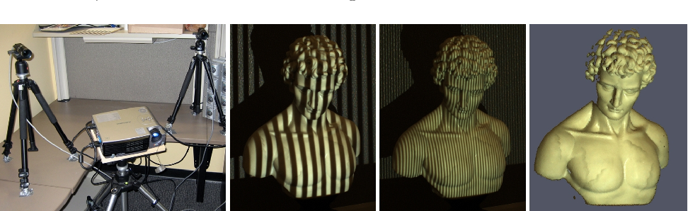
3) Wall thickness analysis with inspection software
Quick and easy digitization and verification with Hybrid Light 3D scanning technology
The EinScan HX combines the advantages of LEDs and lasers to increase the adaptability of scanned materials and ambient light to another dimension and predetermine the use of the device in complex industrial applications. In fast scan mode, a blue LED patterned light is used to collect data about an object. Three-dimensional data can be obtained quickly without the use of control points. The laser scanning mode is equipped with multiple blue laser lines for high precision and allows you to quickly scan reflective metal surfaces in 3D, providing high quality 3D data for reverse engineering, CAD/CAM and 3D printing. nine0003
The mold factory made a 1.5 m × 1 m aluminum mold according to the customer's needs. Due to significant differences in manufacturing equipment and technology, in many cases, the mold cannot achieve the required accuracy after manufacturing. For this reason, mold measurement becomes a necessary step in the manufacturing process of industrial products.
Due to the large size of the aluminum mold, traditional hand-held measuring tools cannot accurately obtain comprehensive mold information. To solve the current dilemma of poor measurement results and inefficient measurement work, a mold factory decided to use a portable 3D scanner to take 3D measurements of a mold. nine0003
Measurement and inspection process
For this measurement process, the mold factory chose the EinScan HX handheld double blue light 3D scanner. By integrating blue laser and blue LED light source in one device, EinScan HX is compatible with various measurement application scenarios. Thanks to the portability, user-friendliness and high scanning speed, the complex production environment in the factory is no longer a difficult obstacle during the measurement process, but a problem happily accepted by the EinScan HX, which greatly improves the efficiency of quality measurement. nine0003
Step 1: Apply control points
The EinScan HX laser scanning mode was selected for this scan. Before scanning, control points were applied to the reflective aluminum mold blank.
Step 2: 3D Scan
In laser mode, the scanning speed is 480,000 dots/sec. It took only 10 minutes for a technician to get the complete high-precision data of the aluminum mold 3D model directly.
Step 3: 3D measurements
To check if the aluminum mold meets the accuracy requirements, the scanned data of the aluminum mold and the digital model of the original design were imported into the Geomagic Control X measurement software. get an annotated variance chart. Finally, the measurement report can be exported.
The scanning process took less than 30 minutes from applying control points to the 3D scan to the final benchmarking report. This method saved a lot of time compared to traditional measurement methods and solved many parametric problems that cannot be detected by traditional measurement tools.