3D printing vertical holes
How to 3D Print Holes Without Supports – Is it Possible? – 3D Printerly
Many people wonder whether you can 3D print holes without supports since they can either be really hard to remove or result in a hole that has material in the way. This article will take you through some useful tips and advice to create good quality 3D printed holes without supports.
There are definitely some interesting tips that you’ll want to read about so have a read through this article for better details about 3D printing holes without supports.
Can You 3D Print Holes Without Supports?
Yes, you can 3D print holes without supports as long as you have a well-calibrated 3D printer and optimal temperature settings. It can be difficult to get a perfect hole shape in 3D prints due to the layer-by-layer nature of 3D printing, but you can make design adjustments to create better 3D printed holes.
If you’re trying to create complex models with big holes, you might be needing support structures, depending on how well your 3D printer can handle the overhangs of the holes.
Now that you know that the idea is definitely possible, let’s get into the process of 3D printing holes without supports.
How to 3D Print Holes Without Supports
To 3D print holes without supports, try reducing your layer height, use an optimal printing temperature, so the material above the holes don’t sag, use good fan settings with a fan duct to blow cool air on the parts, and design the part with a teardrop shape to create clearance for the top of the hole.
The video below by Maker’s Muse goes through some great design tips that you can implement to 3D print better holes and without supports.
One of the first tips he mentions is how you can create “teardrop” holes rather than circular holes in your 3D models, mainly for horizontally-aligned holes.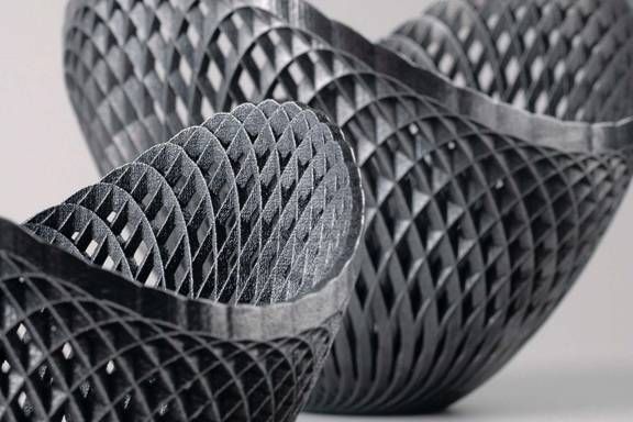
Due to the way 3D printers create objects layer-by-layer, the top of a circle would be a flat layer of extruded material rather than the rounded shape we are looking for, so creating a teardrop hole helps to account for this by adding more of a clearance to the top of the circular hole.
It should reduce the need for you drilling out the hole and removing any flat spots from the surface. The video shows you how this looks in Fusion 360, a CAD software. It’s more important for larger holes and you may be able to get away with not doing this for smaller holes.
The second tip he walks us through is to use a slot to create some movement for the hole to open up and insert your chosen object, which can then be clamped up afterwards.
He does this by inserting a rectangular part within the circular hole which gives it space to open and close up.
The third tip for designing better 3D printed holes that don’t need supports is similar to the slots, but using “fingers” that are small open spaces just above the holes you want to 3D print.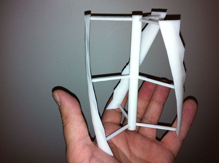
They allow for the plastic to slightly deform and fit the object you want to put in the hole.
The good thing about this is how it still holds the object tightly since it doesn’t have a lot of space to move around. He mentions that it’s a lot easier to create than it looks, so definitely try it out if you are designing a 3D print with holes in it.
I’d recommend also looking into using good part orientation, or rotating your model sideways so the hole is built up vertically rather than horizontally. Your 3D printer would just be extruding material around the hole, making it a lot easier with gravity working in your favor.
It works best with smaller holes, but can still work well with larger ones.
If you’re an advanced user, it might be worth looking into the following video that talks about 3D printing floating holes without supports.
The idea explained in this video is all about making bridges right below the hole. You can create two rectangular and square-shaped layers before the hole to create a bridge and let them act as support structures for the hole.
This is definitely a complicated technique and only advised for those with fairly decent design skills in software such as AutoCAD or Fusion 360. If you think this is something that you can handle, the video above can surely help you out.
Furthermore, it’s also possible to print holes in 3D prints without supports by changing the shape of the holes.
It’s reported that diamond-shaped holes instead of regular rounded ones in 3D prints can actually give you self-supporting angles. This takes away the need to place support structures around the holes.
Other benefits of using diamond-shaped holes include reducing the print time and the material used, although it will depend on your print for the most part.
You can look into doing this as well, although you will need to design the diamond holes yourself in a CAD software. Again, this is an involved process that does warrant a basic level of design skills.
A unique method that was recently released in Cura is to use a support that extends out from the side, called the “Arch Buttress” under Custom Supports.
The video below by CHEP goes through exactly how to create these supports using a plugin from the Cura Marketplace called Cylindric Custom Support. You can orient your print as normal, then create these supports that can be removed without being troublesome.
This is mainly directed towards filament 3D printing, but if you were to create similar objects with a resin 3D printer, creating holes would be a lot easier since the layer heights are very small.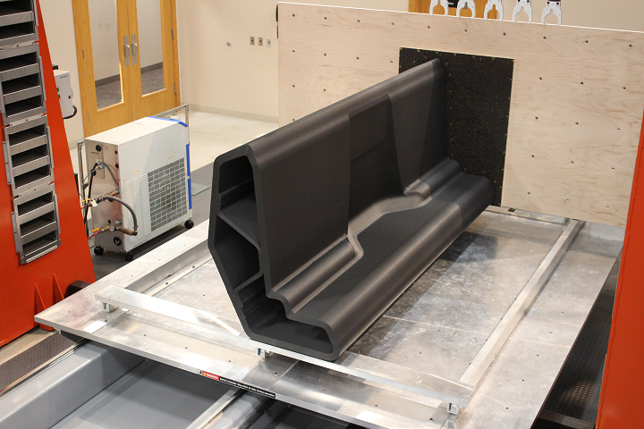
With a 0.05mm or 50 micron layer height, along with the accuracy of resin printing, creating holes would be more feasible.
How to 3D Print Spheres Without Supports
If you want to 3D print a sphere without supports, consider splitting it into two for the best results. You can use any splitting tool to divide the sphere into two parts.
I really recommend referring to my “How to Split and Cut STL Models for 3D Printing” guide for an in-depth tutorial on how to do that.
After you print the two parts of the sphere together, you will need to attach them together. 10-15 minutes of post-processing will do the trick here.
The following video by My Tech Fun actually talks about a brilliant way of 3D printing spheres and that too without having to use supports.
What you basically do to create some really perfect spheres is to first divide them into two hemispheres and make holes in each hemisphere.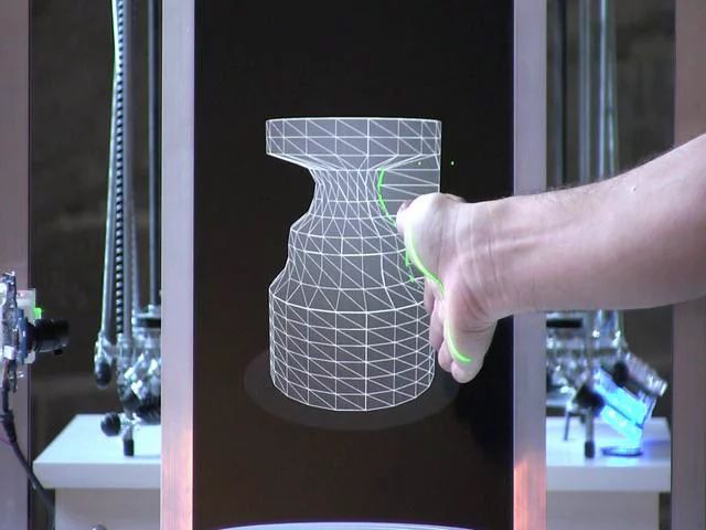
You can then use a set screw that can fit inside the holes painlessly and allow you to screw the two hemispheres together. The best part is that you can 3D print the set screw too in accordance with the diameter of the holes.
However, this is only suitable in cases where it doesn’t matter in what way your sphere can rotate. For example, if you want to print the globe of the earth, the screwing technique might not be very suitable.
Instead, you can use drilling as a technique.
While we’ll get into the process of drilling more in-depth in the next section, it’s worth mentioning here that you can drill four holes in each hemisphere, fill it with glue, and use a piece of filament in each hole to connect the two hemispheres together.
You can see how it’s done in the video above. It’s really an intellectual way of 3D printing spheres without supports.
Can You Drill a Hole in PLA & 3D Prints?
Yes, you can drill a hole in PLA and 3D prints, but you have to be careful not to overdo it and damage the print. ABS can handle being drilled better as it is less brittle than PLA. In addition, it’s better to have holes in your part designed already so they can be drilled easily and give you the best results.
There are a couple of things to be aware of before getting into drilling PLA and other 3D printer filaments. People often ask the question, “Can you drill a hole into 3D printed plastic?” but the answer isn’t always straightforward.
It’s definitely possible to drill holes in PLA, but you have to make sure not to drill parallel to the layers as it can cause layer-splitting in your parts, which is also known as layer separation. Try drilling perpendicular to the layers for the best results.
Moreover, a firm part is more likely to be drilled nicely as compared to a brittle one. Even if you’re working with PLA, heating it up to about 48-50°C using a hairdryer or anything similar can definitely help.
Another useful tip, in this case, is to place a hard block of something like wood to avoid breaking your part and preventing the drill bit to jam.
Speaking of which, I recommend picking sharp bits over dull ones when drilling 3D printed parts for better performance. There’s definitely a learning curve here that you’ll overcome with experience, but you’ll get there eventually in due time.
The following YouTube video actually shows how to drill 3D printed parts. Do give it a watch for a thorough visual explanation.
How to 3D Print Without Supports
To 3D print without supports, you can lower your layer height, decrease the print speed, and reduce the temperature to achieve better overhang angles, so you won’t need supports. You can also try changing the part orientation to see if it can print without supports. Splitting the print into parts is also favorable.
3D prints that don’t need supports are usually the best ones because they eliminate a very time-consuming and often harmful-to-the-print part of the post-processing phase.
However, some parts are impossible to create without supports, but you can always implement some techniques to minimize the number of supports used, or remove the need to do so altogether.
One of the first things that you can do to 3D print without supports is to tweak your slicer settings. The following parameters need to be tuned in order to achieve higher overhang angles without needing supports.
- Layer Height
Generally, a higher layer height, about 0.3mm as opposed to a 0.1 or a 0.2mm layer height will allow your print layers to go longer lengths without being supported.
- Temperature
As for the temperature, it’s recommended to reduce the extrusion temperature by 5-10°C than what you’re using for the best results. You can either do this or increase the cooling on your part for achieving better overhang angles.
- Outer Shell Wall Speed
The Outer Shell Wall Speed can be set at somewhere around 5mm/s, so the overhangs can be printed slow and given enough time to cool down, but you can actually keep this setting high by implementing another useful setting, mentioned below.
- Overhanging Wall Angle
- Overhanging Wall Speed
These are settings within Cura that allows you to adjust wall speeds only for a specified overhang angle. Cura defaults the Overhang Wall Angle at 90° which is turned off, while 0° would be every wall being treated as an overhanging wall.
When you lower this angle, it will start reducing your Wall Speed in those angled areas, at a set percentage.
You can find these settings under the “Experimental” tab, or by searching for “Overhanging”.
An example of an Overhanging Wall Angle would be 70° and an Overhanging Wall Speed of 50%, so that any angles that are 70° and above would slow down the print speed by 50%.
One person who made use of this setting mentioned that they had great success with these features for printing unsupported walls at up to 70° without sagging.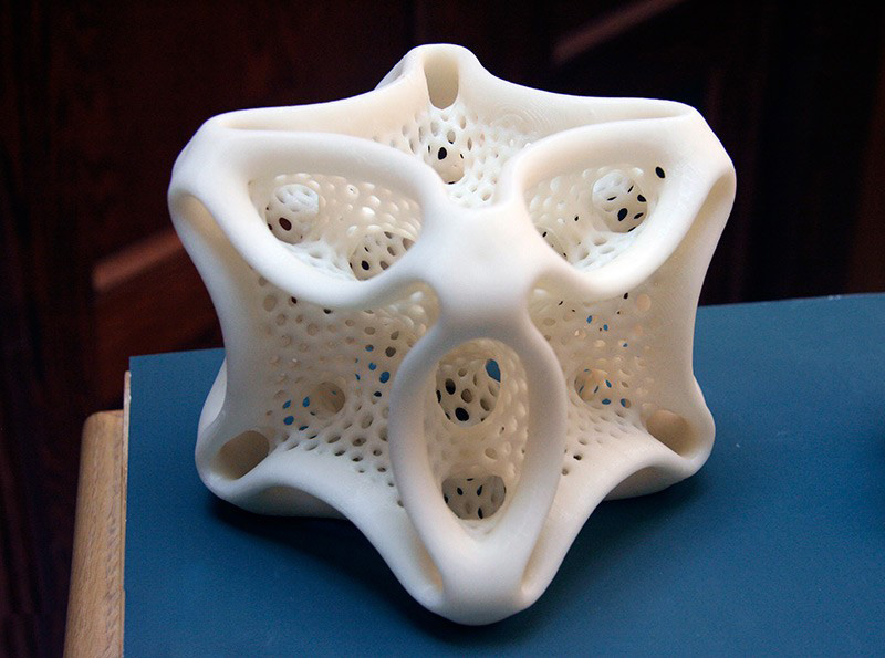
Another user mentioned that they had an idea to use an Overhanging Wall Speed above 100% because they had tiny overhangs that would print better at higher speeds, so it can really be used to your advantage as you desire.
The Massive Overhang Test on Thingiverse is a 3D printer calibration test that you can use to really dial in your 3D printer’s settings and print overhangs better, so I’d definitely recommend that for practice and trial and error.
On a side note, check out the 20 Best & Most Popular 3D Printing Calibration Tests to dial-in your printing machine like never before.
The following video by The 3D Print General goes over these slicer settings in detail by utilizing the aforementioned Massive Overhang Test, so check it out for a more visual explanation.
Another point worth noting is that supports connected to the base of the model are relatively easier to deal with as compared to the supports used somewhere on the body of the print.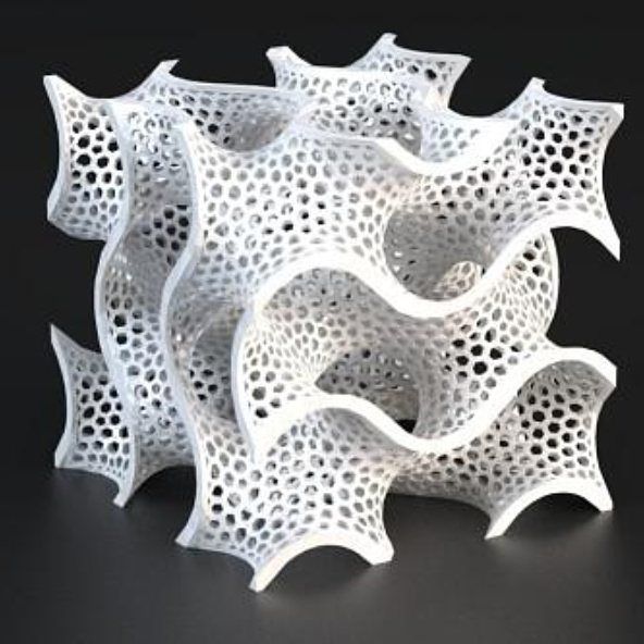
You can orient your parts in such a way so that their overhangs don’t go very far, like beyond 45°. That way, you would only need to put some supports at the base of the model, which is not only easy to remove but also very doable as a whole.
In addition, if you’re struggling to print parts with supports, you can try searching for their support-free versions online.
The Mandalorian Miniature by Velrock on Thingiverse is a fairly complicated model that requires Cura’s Tree supports to be printed effectively.
Another Thingiverse user called icfirz has actually created a remix of the model and made it support-free, so you really don’t have to trouble yourself with printing supports for The Mandalorian Miniature.
If you’re someone with good design skills, you can actually modify a model in a CAD software like Blender to make it support-free.
If that isn’t a possibility, it’s always worth looking up for any remixes of your specific model to see if anyone has made a version of it that doesn’t need supports.
The following video by Maker’s Muse also goes over some ways of designing 3D prints that don’t need support material.
He talks about using a technique called Sacrificial Bridging. This is when you print a small, yet rigid layer of material beneath the part where support would usually be required thereby forming a solid foundation for the rest of your print.
Although the bridge acts as support, it combines nicely with the rest of the part and doesn’t appear to be a proper support structure. The video above goes more in-depth on this, so do check it out.
Why do Holes And Cavities Come Cut Undersized in 3D Printing?
It’s been a common complain that, although the part geometries have a near-net shape, some of the part features like holes and cavities are compromised at times.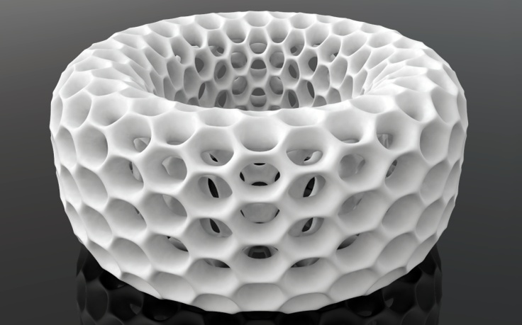 It’s been an observed trait in 3D printing that the holes oriented vertically (Z) w.r.t to the laser direction yield elliptical, undersized holes as compared to holes oriented horizontally w.r.t the laser direction (X-Y).
Before we start accessing this problem, we need to dig a little deeper into the 3D Printing process, in general, to understand this phenomena better. And while we’ll be commenting on this aspect with respect to SLS technology, this phenomenon is omnipresent irrespective of the process chosen in 3D printing.
To begin with, 3D Printing is a manufacturing technology wherein material is fabricated layer by layer. Since these layers are flat, material is deposited in a planar manner. Thus, if there’s a curvature, and if you were to zoom-in microscopically on its surface, you’ll see a staircase pattern.
To elaborate this phenomena of undersized holes, let us consider a cube as shown in Fig a. with horizontal and vertical holes cut in it. Let’s name them “A” and “B” respectively. On observation, one can see that Hole A is facing the laser whereas Hole B is oriented normal to the laser direction.
Fig. a
Resolution of a 3D Printer is the smallest part dimension that can be captured and reproduced. It is important to know that in case of the SLS technology, the print resolution in the X-Y direction i.e the smallest part dimension the laser can sinter in the X-Y direction, corresponds to the laser spot diameter which is approx. 0.4mm. Whereas, the print resolution in the Z-direction corresponds to the layer thickness setting. The average layer thickness value in SLS technology is 100µm or 0.1mm. Finer the layer thickness, better the resolution in Z-direction.
Fig. b
The laser is free to trace any part geometry corresponding to 3D CAD. In case of hole A, the laser will scan and sinter the circumference of hole A, thereby achieving a near net shape. But when it comes to fabricating hole B, the Z-resolution will play an important role as the hole is oriented vertically.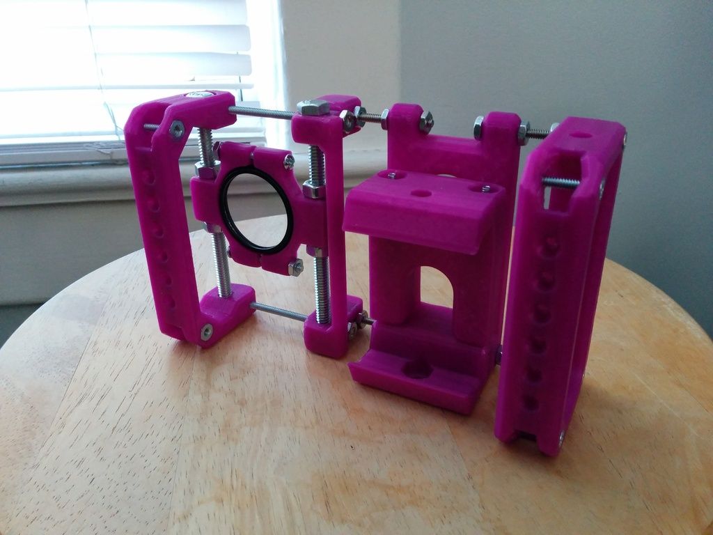 Since the layers are planar, the topmost and the bottom-most layer constituting the circumference of the hole will always be a straight line instead of a curvature as shown in Fig. b. Thus hole B will come out undersized as shown in Fig. c. The ovality can be mitigated by opting for a finer layer thickness. Because finer the layer thickness, thinner the layer height and thus, thinner the topmost and the bottom-most layer.
Fig. c
One other major reason apart from the one mentioned above as to why the holes come out undersized is that, when holes are oriented vertically, the topmost layers try to exert a force on the bottom-most layers. This results in sagging of the bottom-most layers thereby leading to undersized holes. For example, as shown in Fig. d, layer P will try to exert force (its own weight) on layer Q. Layer Q will in-turn exert a force on layer R. As a result, layer R will be pushed downwards. This domino effect of top layers exerting forces on the bottom ones will result in sagging of layer R which causes the circumference of the hole near the top to droop and results in undersized holes.
To resolve this issue, care has to be taken while orienting the part geometry. Holes should be oriented in X-Y direction. In case there’s a part geometry having holes in both the direction as seen in Fig a., the critical holes should be placed in the X-Y direction, whereas the non-critical ones should be oriented vertically. These vertical holes can later be drilled to achieve a near-net shape. Generally, we recommend that a stock of 0.5mm be kept on the hole diameter which can later be machined to achieve precise dimensions.
Opportunities in the Semiconductor industry
Nishant Kashyap July 28, 2022
Impact of EV on Component Manufacturers
Nishant Kashyap July 28, 2022
Automation, Robotics, And The Factory of The Future
Nishant Kashyap July 4, 2022
How Much Will a 3D Printer Cost in 2022?
Nishant Kashyap December 14, 2021
What is Delrin?
Nishant Kashyap December 8, 2021
What Are the Advanced Industry 4.
 0 Technologies?
 Nishant Kashyap December 2, 2021
Prototyping workshop - 3D printing, milling, scanning, electronics development
Rounded corners problem during printing
It is clear that due to the round shape of the nozzle of a 3D printer, when printing parts, it is impossible to make their corners perfectly sharp. In addition, when printing square corners, depending on the speed, additional plastic build-up may occur due to the print head slowing down when passing the corner of the part. For example, when the head slows down, the pressure of the nozzle increases, as a result of which a layer of plastic is squeezed out a little thicker than if a normal straight surface was being printed.
This effect is noticeable in the photo below - although the corner of the part was perfectly square in CAD, the printer could not print such a corner. Even worse in the photo looks a slight influx of plastic from above.![]()
It seems that in most cases a rounded and slightly enlarged corner will not be a problem, but what if you are trying to print a square part that should fit into a square hole, such as a lid?
If you want to avoid this problem, then it is enough to make the corners slightly rounded in advance, at the model development stage.
Printing of finished assemblies
Models are built layer by layer on a 3D printer. Perhaps this fact can be used for some trick. So, for example, in some cases, a 3D printer can print a product consisting of different parts, immediately assembled, and not print each part separately, in order to then assemble the product itself from them.
When developing models of this type, it is necessary to make sure that the various parts of this model cannot stick to each other, as well as move relative to each other. This situation can happen when you have one part printed directly on top of another part, and this can be a big problem when printing because the filament extruded directly in the air will bend unpredictably, which will lead to sagging of the top of the product, due to which it can stick to the bottom.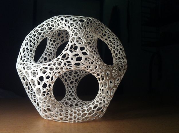 To avoid this type of problem, it is very important to leave a sufficient gap between the parts of the printed product, and the width of this gap for each case will be individual.
For example, if the overhanging part of the part is very small, say 10mm in diameter, then you can set the gap height to 0.5mm. Well, if the overhanging part is long, or has a complex geometric shape, then, accordingly, its sagging will be much greater and, therefore, it is necessary to proportionally increase the height of the gap. The easiest way to figure out how much gap to set is to try to see how the problematic part of the model will print. By creating small test models, you can spend much less time on plastic than if you printed the entire product every time you try to eliminate errors.
The illustrations below show an example of a composite product printed as a single piece. This is a folding dust filter.
Top image - complete filter model
The lower image is a section of the hinge (loop) of the filter
As you can see, the hinge (hinge) has some 45 degree protrusions, which allows the 3D printer to easily print the part, as well as avoid the sagging problem that would lead to the hinge (hinge) parts sticking together.
When you work in 2D space, with the X-Y coordinate plane, you can create parts of models with fairly tight tolerances. So, for our part, the minimum gap is only 0.2 mm. But there is another problem that you may encounter - this is the so-called stretching of plastic threads between adjacent parts, which again can lead to gluing parts of the product.
You can get more information about this problem and how to fix it here.
Of course, you can print not only connected parts of one product. So, as one very common example, you can bring a whistle that has a ball inside, and this ball is printed from the very beginning along with the whistle itself. At the end of the press, the ball is pulled out of the whistle, but in such a way that it remains inside, due to this it can sound freely.
The cost of printing does not depend on the complexity of the form
By this heading, we mean that the printer doesn't care whether it prints a cube or an intricate set of shapes. There is no doubt that printing a simple cube does not require a large number of nozzle movements, so the print time will be lower compared to complex models. But if you omit this fact, printing complex forms is definitely beneficial, because the cost of printing does not actually depend on the complexity of the form.
A classic example of this idea is commercial aircraft parts such as the bracket in the picture below. We can optimize its shape by not cutting it out of a solid piece of metal, but printing it out of plastic on a 3D printer.
Image taken from Airbus.com
We believe that with traditional manufacturing tools, we will never be able to create perfect voids in the model, unless we can make something similar to such voids with drilling/milling. But, when using 3D printing, we have the possibility of placing a cavity under a thin layer of plastic, which further increases the strength of the model and reduces the mass of parts and consumables.
Connection of large parts
Even with 3D printers such as the Ultimaker and Ultimaker2, which have fairly large printable areas, there may be a situation where you need to print a part larger than the printer's printable area. To get out of the situation - we will divide the model into several parts, print the parts separately, and then connect them together. The easiest way to connect is to glue the parts together. Obviously, this way we will achieve the desired result, but do not forget that we are using a 3D printer, so why not get creative?
But let's get back to gluing for a second. For convenience and smooth gluing of parts, as well as to facilitate this process, you can add holes and round pegs to them on the corresponding sides of the models. As a rule, this is enough to be sure that the parts are connected correctly and, while the glue dries, not only places will not move, but also relative to each other.
If you need to glue a rather narrow part to a wide one, then in this case you can print special guides that will fix the glued part in relation to other parts of the part.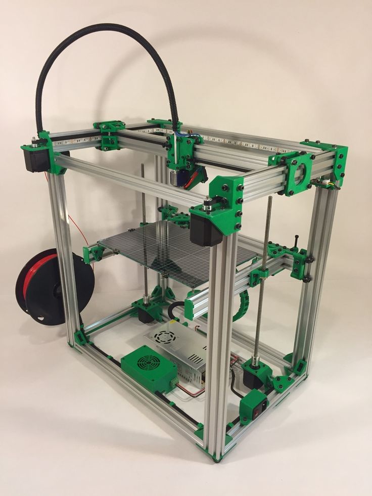 Make a couple of mounting holes in the parts to be joined, then fasten the guides, leaving a small gap so that when gluing the parts, the location of the parts remains correct.
If you don't like the way parts are glued together, you can peep a few ways from carpenters. For example, the dovetail joint is used by woodworkers and there is no reason not to use it in 3D printing.
This complexity of design does not complicate the manufacture of parts, you can also leave the connection temporary or fix the parts together with glue.
Assemble to print all parts in one go
It is always tempting to print a large part at once, but as often happens, fixing its first layer on the platform and then printing the whole part evenly is quite problematic. Therefore, do not be afraid to print several details at once. Here are a couple of reasons why it's best to print some parts piecemeal: first, you can get rid of supports, which, let's face it, take a very long time to remove; secondly, thanks to this method, the strength of the part can be significantly increased.
Let's look at the first reason. Surely you have encountered the difficulty of printing protruding elements of parts. Of course, the best option when printing overhangs is to eliminate them at the stage of product modeling. But, if this is not possible, then you can divide the model into several parts and arrange them in such a way that the protrusions are no longer a problem.
The figure shows an example of a part that is difficult to print at one time, regardless of its printing position. For printing, you will have to use a large number of supports, which will lead to high material consumption. But, if you break the model into two parts, then printing will be much simpler, and instead of removing the supports, it will be enough for you to connect them with glue. Pay attention to the added chamfers at the hole and the peg - this is done to simplify the connection of parts of the part.
Strength is another reason for splitting a part into several pieces. If you need to print a narrow cylinder perpendicular to the substrate, then it makes sense to print it separately, lying on the table, this will give it strength, since the printing direction will be along the longitudinal axis of the cylinder.
How to make the fixing of perpendicular parts of the part stronger
Suppose you want to print a vertical cylinder on a cuboid. At the junction of the figures there will be too sharp a transition, due to which the part may break if you press on the cylinder. You can strengthen the part by adding a ring of the appropriate height to the model at the junction of the figures (see the figure below).
Addition of metal elements to increase the strength of plastic parts
Currently, the vast majority of 3D printers print with various types of plastic, but compared to plastic, metal has much more durable characteristics. Why not try to combine the best of these technologies? We can use the print pause function to add iron parts to parts and then resume printing. A great example is to insert metal nuts into the right places of one part, then to screw it with screws to another part.
Make sure you have enough material around the nut, otherwise the nut will play when you tighten the screw. Strengthening the area around the nut can either be done by printing a few extra lines around the perimeter or by tricking the slicer into 100% infill where needed.
How to print horizontal holes
When printing horizontal holes, the top edge overhangs and creates an arc. This means that the horizontal holes will be slightly flattened at the top and will shrink in size. There are several ways in which you can align the holes.
The first approach is to reshape the hole during the modeling phase, making the hole look more like a water drop. This makes the printing process easier as there is a slight gap for the plastic to sag during printing.
You may not like the look of the resulting hole. In this case, there is another way that you can use. It consists in creating a thin support membrane that supports the edge of the hole in one of the places.
If you don't care about the appearance of the hole and are going to use it for practical purposes, you can also experiment with different hole shapes. How about a triangle or square with one of the corners pointing up? Basically this idea is useful for small holes. Remember to leave clearance around the hole if a screw will be inserted into it.
Strength increase due to 100% filling
3D printer uses different software. And some programs do not allow you to set multiple plastic fill options during printing. In such a case, to increase the strength of the part, you can increase the amount of plastic fed or the number of perimeter walks for the entire part.
But you can use one trick to overcome this shortcoming and create a model that prints more plastic in the areas where you need it. The method consists in adding a group of cylinders in the place where more strength is needed.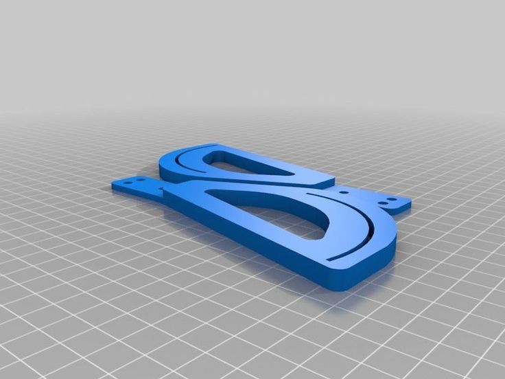 This will force the program to print many cylinder print lines, which will fill the area more densely.
The illustration below shows an example of this trick. It shows a product in the form of a box with a little excessive filling. In this case, cylinders with a diameter of 0.5 mm were used at a distance of 1 mm from each other. For each specific situation, you will have to experiment with the dimensions of the cylinders and the distances between them in order to find the optimal values. Cylinders must necessarily cross the upper and lower planes, otherwise unpleasant situations may arise during printing. Play with the settings (for example, in Cura's "Fix horrible" slicer) so that the slicer doesn't throw cylinders out of its calculation. In any case, in the program, before printing, it is necessary to check the appearance of the layers.
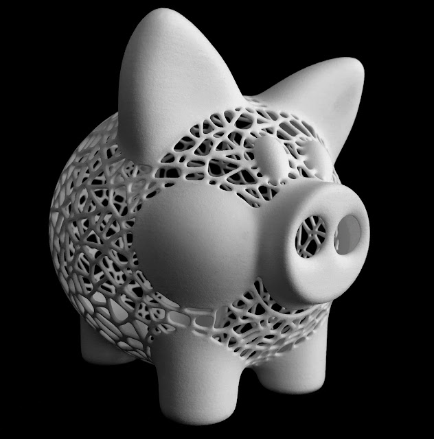
Below is another example where we added many small holes around one large mounting hole. It turned out not one hundred percent filling, but, nevertheless, unlike the hole of the same size on the right, it is much stronger.
Round corners to reduce distortion
Curvature occurs more frequently at sharp corners, which are areas of increased stress and material stress during printing. By rounding the corners, you will slightly reduce this effect.
Strength-oriented optimization
To get an idea of how durable your printed parts are, try imagining they are made of wood. If you've ever chopped wood, then imagine that it's much easier to cut along the fibers than across.
Think about your printed parts in this way. Position and design them to be as solid as possible. If you have a complex part with sticking out parts, then you can break it into several parts, and then assemble it after printing. By doing this, you can not only save time, but also get rid of supports.
Consider plastic shrinkage after cooling
We have already noted that parts after printing tend to decrease in volume when cooled. This is especially problematic for small holes. To avoid this, you need to scale the holes to compensate for shrinkage. Over time, you will gain experience, and will automatically understand how much to scale the element to compensate for compression.
It is worth noting that if your model has few polygons, then this will also lead to a decrease in holes. Since the hole is a series of straight lines, the low number of polygons means that the lines will run over the diameter of the hole. As a rule, this situation will not lead to a strong decrease in size, but it is still worth remembering this.
For a better understanding of the downsizing problem, you can print a model with different hole diameters and compare which size is in the computer model and which one is printed. This will help you better scale the holes while modeling.
Model closure, what is it and why is it important?
A model that is not "closed" cannot exist in the real world. This means that the model has edges or vertices floating in space, areas of zero thickness. This also applies to "permeable" models, which, for example, have holes in the form of a grid.
It is important to correct these errors as they can confuse your slicer and lead to unpredictable print paths. There is a free online service for fixing such problems, you can find it here.
It may also be worth trying to change the export settings in your CAD to avoid errors. A setting such as the resolution of the exported model may solve the problem.
Wall thickness
If your model contains thin walls, it might be a good idea to make them multiples of your nozzle width (0.4mm for UltiMaker2). If you make the wall thinner than the width of the nozzle, it is quite possible that your program will remove it from the model entirely if it realizes that it cannot properly print such a thin wall.
45 degree rule
When designing the model, you should try to keep the angles of the protrusions to a maximum of 45 degrees.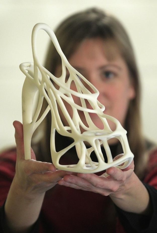 The printer is capable of printing angles greater than this angle, but if you are aiming for good surface quality, then reduce the angle as much as you can. The steeper the angle, the worse the print quality.
The illustration shows how models could be designed for the best possible 3D printing experience. The first image shows that the top of the model has an obvious overhang that must be maintained if the goal is to print correctly. Of course, it is possible to print the part using supports, a little more about this will be written below.
The image in the middle shows a 45 degree overhang angle change for easy printing. But, of course, this is not always possible. Alternatively, this part should be used as a belt roller, which should be in the middle and have stops.
In the third version, we split the model into two parts, and added a pin and a hole so that the parts can be glued together after printing. This approach keeps the edges straight.
Create your own supports instead of automatically generated ones
Whenever you have a part of a model hanging in the air, you need print supports. They allow you to print parts that are usually impossible to print just like that. The bad thing is that after removal, they leave scratches on the surface.
Lifts can be generated automatically or you can make them yourself. Most printing software makes supports automatically and they do the job, but these supports are difficult to remove and leave scratches on the surface. An alternative would be to use a separate program, such as Meshmixer (link). While the built-in generators create a "block" of support structures under the overhanging part of the model, Meshmixer instead tries to use small columns of material for support. An excellent guide to using this program can be found here.
But the best way is to create supports manually when developing the model. Humans are still smarter than computers in this area and can be a little more resourceful about how best to build support. So you can save printing time and plastic. You can also prevent and hide any scratches. The picture below shows the overhang and two supports in red.
This image shows automatically generated supports. Note that the default settings have been applied. But you can tweak some settings to improve the result a bit. In our example, ironically, the automatically generated support itself requires support.
In the image above, the homemade support (highlighted in red) nicely supports the protrusion and we can take advantage of the 3-D printer's properties to apply material at small intervals. The printer will start printing around the perimeters that are fully supported by the custom supports. These perimeter lines will form the base for the plastic that will be applied to the rest of the gaps.
When creating the support, it is important that you leave a small air gap between the support and the actual model so that the support does not blend into the rest. What the gap should be depends on the height of the layer and how the model looks. As a rule, a gap of 0.15 mm is used.
Create lintels instead of a steep canopy if possible
As mentioned above, supports leave scratches on the surface. They also waste a lot of time and plastic. Therefore, you should try not to use them.
The printer cannot print what is in the air, but it can print small bridges in the air. We call this effect the "bridge" effect, as it essentially stretches a strand of plastic between two bases, similar to the cables on suspension bridges. On this page there are a large number of different models printed on different types of printers that use jumpers.
Using the bridge effect is very useful when printing models such as a model of a house with open windows. A short span over an open window can be easily closed with a "bridge", saving both time and plastic.
This does not mean that the bridge effect is miraculous, of course it has its own problems. For example, you can't bridge long gaps with bridges and still expect the bottom surface to look perfect, as sagging plastic threads are inevitable in this case. Short spans, however, may not be a problem. To reduce slack, it's best to slow down the print speed and make sure the extruded filament cooler is working so well that it becomes stiff as quickly as possible.
This image shows a typical case where a "bridge" might be a much better choice if the design allows it. A gently sloping overhang is likely to have very poor surface quality on the underside. By making a straight bridge, you can improve the print quality. If you want a flat overhang, you can of course use a support to print it, but again, the surface will be rough.
The illustrations below are printed models illustrating the quality of the surfaces.
Slopes and stepped slopes
Since the printer creates an object by superimposing one layer on another with some offset, the "ladder" will be visible after printing, and not a smooth curve. If you are a gamer, then this “aliasing” effect is most likely familiar to you, it looks similar.
You won't notice this effect on a vertical surface as the layers will be on top of each other. As the angle increases, the effect will become more and more pronounced. You can soften it by lowering the layer height. The illustration below shows this.
As you can see, thinner layers can render the true shape much better. Also notice how much worse the top of the object looks compared to the bottom layers. As the angle increases, the rings become more visible.
Currently, some printing software (including cura) does not allow you to select (or automatically detect) areas that need thinner layers to reproduce the detail in the best possible way. So if you find that you need extra resolution then print the entire object with a lower layer height. Of course, this will increase the print time a lot.
We suggest you use the Slic3r program. This slicer will allow you to select different layer heights for different print areas to get the best quality and print speed.
But, of course, there are other alternatives, such as trying to design your models in such a way that their slopes are not very smooth and streamlined.
Plastic shrinkage
Unfortunately, this is only a small part of all the problems that you will encounter if you are trying to create parts with very precise dimensions. The degree of shrinkage depends on many different parameters, such as: type of plastic, shape of the part, cooling, heating / no heating of the base, etc.
In short, there are many nuances. This problem is not unique to FDM printers, it also affects injection molding, for example. The molding also needs to compensate for how the plastic will shrink in angles and dimensions.
So how do we deal with this? We are experimenting. Consider an example - usually vertical holes are smaller than expected. The problem is exacerbated if these holes are small. So if you want the hole to fit an M3 screw when printed, you have to make the hole in the CAD bigger than it needs to be. If you want the screw to sit quietly, you can try, for example, a diameter of about 3.4 mm. You can print part of the part, measure the result, and then modify the CAD model with the desired hole dimensions. This is not an exact algorithm of actions, but with experience you will automatically determine how to compensate for shrinkage in order to achieve a good result.
You must be surprised that vertical holes are especially troublesome to print? The answer is simple - when you print a hole, the plastic sags down into the void below it (obviously), since the plastic behaves almost like rubber (when heated), which shrinks.
In addition to shrinkage, as you can see, the first layer is usually printed flattened, resulting in an even smaller hole. The use of a chamfer will help to cope with this problem.
Use a chamfer to print a quality bottom edge
The first layer is usually pressed against the platform more strongly than subsequent layers. This is to ensure that the first layer adheres better to the platform, and as a result, the lower surface is smooth, like a mirror. The downside is that the dimensions of the first layer are larger (or smaller depending on how you look at it). You can negate this effect by adding a fillet to the bottom of your model. Depending on the height of the first layer and the height of the layer for the rest of the print, rounding can be from 0.4mm to 1mm. The gap will give the plastic some room to expand.
It is important that you can use a chamfer instead of a fillet. Rounding will create a serious overhang that will look ugly. The chamfer, as a rule, is done at 45 degrees, the printer will be able to print it very beautifully.
If you still want a fillet on the bottom of the part, you can make a chamfer and make a fillet on the top. By doing so, the overhang will fail. The picture above shows the difference. Note that the red highlight is the overhang, which will be difficult to print compared to the slight 45 degree angle from the chamfer + fillet.
A trick to create a beautiful top
In addition to the information provided here, there is a very neat trick that was first introduced by Dreamworker on the Ultimaker forums. This trick is useful for parts with a flat top that has holes in it.
Dreamworker suggested covering the lid with plastic, covering the holes. In this case, the thickness of the coating layer was used twice the thickness of the print height of one layer of the printer. So if you print with a layer height of 0.1mm, you cover the holes by 0.2mm.
This illustration shows normal printing on the left and overlay printing on the right.
This result was expected. The part on the right was printed using this trick, after which the excess plastic was cut off to expose the hole. There is a difference, right?
Copyright information
We don't mind if you take our guide to use it on your site for non-commercial use, however we require you to add a link:
Excerpt from "Tips for creating models for 3D printing" by 3DVerkstan
Printing holes on a 3D printer - RK Gadget
When 3D printers print holes, they tend to go beyond the small size, even if the linear dimensions of the object are accurate. There are several reasons that make holes smaller than they should be, and we will talk about them today.
Cut error
When CAD systems convert cylinders to triangles, they create a polygonal prism, so the holes represented in the STL file are polygons with vertices on the circumference of the original circle. This means that the sides of the polygon are inside the circle, reducing it by cos(π/n).
You need 10 vertices to reduce the error to 5% and 22 to 1%. So this error quickly becomes small as n increases, but this creates another error:
Segment pause
When the circle is broken into many small segments, the startup time for the segment becomes significant. Reprap has been hit very hard by this in the past and I'm not sure what the current status is. Slow serial communication and complex floating point firmware add pauses in which additional filament can flow from the nozzle.
I've never suffered from pauses because I'm using a 100 megabit ethernet connection which has very low latency and the data is transferred in binary form and in the units my firmware works in. This means that no further processing is required other than calculating which of the three axes should go furthest. However, I use trapezoidal acceleration on each segment, so for very short segments the average speed will be slightly lower.
Arc shrinkage
When a flat strip of thread is bent into an arc, there is too much plastic on the inside of the curvature and too little on the outside. This makes the inner and outer edges smaller in diameter than they should be. Adrian calculated the formula for this here: http://reprap.org/wiki/ArcCompensation. The formula comes out with a too small number. I think there is a secondary effect:
Cutting angle
When the thread is dragged around the corner, it likes to shorten. It depends on how elastic the thread is and how much it stretches. I think that when the nozzle moves in a circle, the filament constantly tries to cut off the corner and ends up forming a circle of a smaller diameter. I think this is the dominant influence on my machines.
Obviously lying to the slicer about how wide your filament is will make the holes even smaller, but that's just a sizing issue.
Ideally all these effects should be compensated for in the slicing software, but what has happened lately is that people are using parametric values in OpenScad to adjust the size of the holes so that they come out directly on their machines. This is the wrong approach, because when the holes come out smaller than they should be, without the cutting software to compensate, then the infill doesn't meet it as tightly as it should.
When I started printing Prusa Mendel parts, I found that the values in the configuration file were too large. I also noticed this when downloading some projects from Thingiverse. This means that my hole sizes shrink less than other people's, which is strange because all the effects above are independent of the printer you choose, with the exception of the segment stop.
Some of the holes in Joseph's (Prusa) pieces are octagonal. This made me realize that low vertex polygons don't shrink. The inside of the hole is defined by straight lines, and they are extruded at the correct location. However, what happens is that the corners of the polygon are rounded. As long as the polygon has a small number of vertices, the corners are far enough away from the circle that they can be rounded off without affecting it. The ideal number of vertices is when the corner cut meets the circle.
I decided to investigate this using OpenScad. I made a script that generates holes from 1mm to 10mm with vertices from 3 to 8, 10, 16 and 32. The diameter of the holes is increased to make the faces of the polygon tangent to the round hole. That is, eliminating the cutting error by dividing by cos(π/n).
I printed the resulting shape on the HydraRaptor and used the drill shanks to measure the holes. This is of course not very accurate, as shanks tend to be slightly smaller than the tip. I inserted the drills into the hole with the most vertices that it will fit.
A pattern emerged where it seemed that the maximum number of vertices you could have before the hole narrowed was twice the size of the hole in mm. The only drill I couldn't fit was a 1mm drill because you can't have a polygon with only two sides. The "1mm" triangular hole at least left a hole, while more polygons filled in completely.
To test this simple rule, I created a new shape with holes from 1mm to 10.5mm in 0.5mm increments with twice the diameter vertices and the diameter increased by cos(π/n).
I have found that all my drills over 1mm fit. The larger ones fit snugly, while the smaller ones are a little loose, probably because there is little friction when only a few tangent points touch.
These two tests were run on a HydraRaptor printing 0.375mm filament from a 0.4mm nozzle. I printed this test again on my Mendel with 0.6mm filament through a 0.5mm nozzle and the drills still fit, so this seems to be universal, at least among my machines.