3D printing threads solidworks
Threads In 3D printed parts
Printing the threads in 3D printed parts is possible, and as you can see from the testing video below it works quite well even in high load end use applications. Through testing we have done here at F3DP we have found its possible to print threads as small as 6-32 or M3 into 3D printed parts. This page will teach you how to go about designing in these threads for 3D printed parts.
Thread Strength Testing: Nylon 12 Material
Tensile strength test of MJF parts with larger printed in threads
Tensile strength test of MJF parts with smaller printed in threads
Thread Strength Testing: TPU Rubber Material
Tensile strength test of TPU Rubber MJF parts, helicoil thread insert vs. printed in thread
What machines is it possible to print threads into 3D printed parts with?Threads in 3D printed parts using an HP MJF machine with Nylon 12
This guide will be specifically talking about threads for 3D printed parts coming off of the HP MJF technology. The MJF machine is unique in that it allows for very fine features to be printed in any orientation without the need for support while still being able to use high strength materials like Nylon. The next closest technology that would be able to produce threads would be SLS, but these machines can’t capture the same level of detail as the MJF so they are limited to 1/4-20 or M6 threads or bigger. Then there are the liquid polymer machines like Polyjet, SLA, CLIP, DLP, ect. These machines can absolutely print threads down to 8-32 or M4, but the hole must be oriented in the vertical direction from the print bed.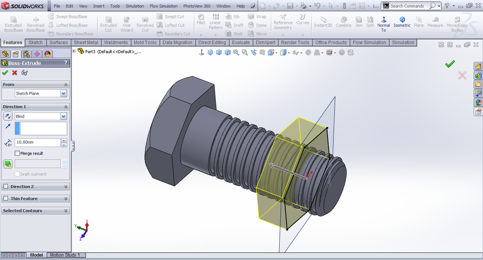 If the hole is horizontal it will end up with support in it and the 3D printed thread will not turn out. Lastly, FDM technology is not suited to print in any threads under 1/2-13 or M12, and they have to be oriented vertically from the machines print bead.
Our in-house engineering group works with all the major CAD software’s, but the one that is the easiest to use for adding threads into a 3D printed part is Solidworks. The reason for this is that it has a built in tool that will automatically add in the correct thread profile for you. For this reason this guide is built around this software, and the following video is a tutorial that will walk you through how to add threads in 3D printed parts:
How To Design 3D Printable Threads – NUTHow To Design 3D Printable Threads – BOLTHere is a really good tap / drill chart for reference.
For those not using Solidworks for their CAD design software we have also collected thread design how to video’s for a lot of the other major CAD design software’s on the market:
Our other divisions:
close ×
Get a Quote:
Upload your files and fill out the information below to begin the quoting process.
Creating Threads in SolidWorks for 3D Printing [VIDEO]
For years, the ability to create a realistic thread in SolidWorks was something of artistic fantasy; a way to demonstrate your proficiency in SolidWorks. The rebuild times on a small assembly would be long enough to get a warm beverage, and on larger assemblies it would be long enough for me to fly somewhere on vacation.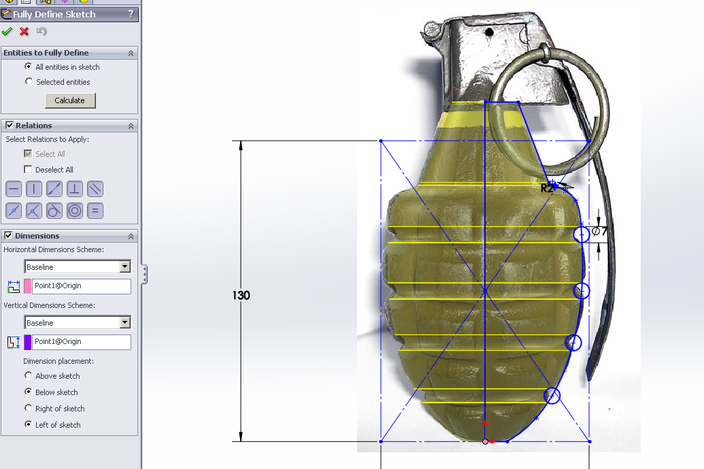 Nevertheless, with the arrival of 3D Printers, the need to create very accurate 3D CAD models of threaded parts is less fantasy and more reality. Of course, there are no shortage of videos out there demonstrating how to model threads in SolidWorks. However, to my knowledge, none of them focus on any sort of “best practices” for creating a thread for 3D Printing.
Some testing we had previously done here at Javelin led us to some pretty complex calculations regarding offsets and gaps at Maximum Material Condition (MMC), but at the end of the day we found that the most reliable method was just to model up the threads slightly oversize, then run the printed part through a tap and die set. Having the threads already modeled up helped to guide the part into the die for a “final” cut. This would also allow it to work accurately with traditionally manufactured parts.
Here’s a video showing how to add the threads to an M6x1.0 Socket Head Cap Screw (SHCS):
Rather than use up a bunch of time making the body for my screw, I was able to simply open the appropriate fastener from the Toolbox by right-clicking on it and choosing Create Part from the menu. This allowed me to configure it to the desired size.
For more information about the utility I used to turn off the Toolbox flag for the part, please refer to this blog article.
To create the thread, I started by creating my Profile sketch. This would ideally come from a standards manual (such as the Machinery Handbook), not made up on the spot as I had done – particularly if you are not planning on using a tap and die set. I made sure to position it in such a way that it will begin cutting in space, rather than in contact with the part. This just protects against rebuild errors at the start of the cut. Then, I created a helix first by sketching a circle, then by using the Helix\Spiral command (Insert > Curve > Helix/Spiral). If it important to locate your helix in such a way that it starts on your sketch plane. This will result in the most predictable behaviour when creating a swept cut. If it does not start on the sketch plane, you will get a swept cut that goes in two directions, which can be difficult to manage. After you have your Profile sketch and your Path (the helix), create a Swept Cut.
I used a Revolved Cut for the undercut, but if you are 3D printing this then the undercut may be unnecessary (depending on your design intent, of course).
3D models for 3D printing. How to create the right 3D model
3D models for 3D printing
Whatever one may say, 3D modeling remains a much more developed and widespread area of 3D technologies than 3D printing techniques. Experts in the field of 3D modeling are enough, but in most cases their main specialization is the construction of 3D models for purposes other than the practical recreation of the latter. But for the production of a quality product using a 3D printer, the presence of a “correct” 3D model is an undeniable prescription.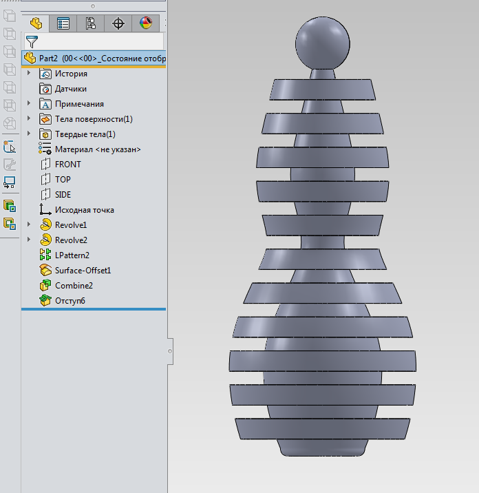 Therefore, the rules for building a 3D model for 3D printing cannot be ignored.
We, as a company specializing in the provision of 3D printing services, often face the problem of incorrect construction of three-dimensional models, which affects both the timing of the production of the necessary samples and the financial part of the issue. In fact, when a client sends a low-quality 3D model that needs to be corrected or completely redesigned, he has to pay twice (if he did not prepare this model himself). In addition, the time to complete the order will increase significantly. It is clear that this state of affairs is not acceptable.
Lack of polygons in 3D model
Probably, the main reason for the occurrence of situations with incorrect construction of 3D models is the lack of knowledge of specialists in this field about the requirements for models specifically for 3D printing. So, let's see what points you should pay attention to when 3D modeling. We hasten to note that everything described below applies only to STL files.
Missing edge in 3D model
3D model requirements for 3D printing
In order for a 3D printer to produce a quality product, a 3D model for 3D printing must meet a few simple conditions, which will not be difficult to observe. The first and most important rule is that the model must have a closed geometry . What does it mean? All 3D models consist of surfaces that form a closed volume. In the absence of one surface (face), the model will not have a physical volume, which makes it unsuitable for 3D printing.
Also, it is essential that the planes that make up the model do not intersect with each other and are connected only by side faces . We often come across models in which triangles literally “lie” on top of each other. As you understand, this will affect the 3D printing process and affect the quality of the finished product for the worse.
3D model with broken faces and inverted polygons
A small theoretical digression: in the STL file, the 3D model consists of triangular polygons that describe its surface. Each triangle (Triangle) has a normal vector - a parameter that determines the inside and outside of the polygon. Of great importance is correct placement of normal vectors : they must be directed strictly inside the model volume. Otherwise, the 3D printer may incorrectly perceive the data on the surface of the product and start printing outside the volume of the model. As a result, there is a possibility that the carriage of the device will crash into the guide axles, which is fraught with serious consequences - damage to both the mechanical and electrical components of the printer.
Inverted polygons in 3D model
In 3D modeling programs, it can be difficult to evaluate all the features of the built sample and the suitability of the 3D model for 3D printing. For such purposes, there is a number of software that not only demonstrates, but also corrects errors in 3D models. An example is the product of the well-known Autodesk company called NetFabb. After loading the file into the program, it will automatically show inaccurate areas by displaying them in red.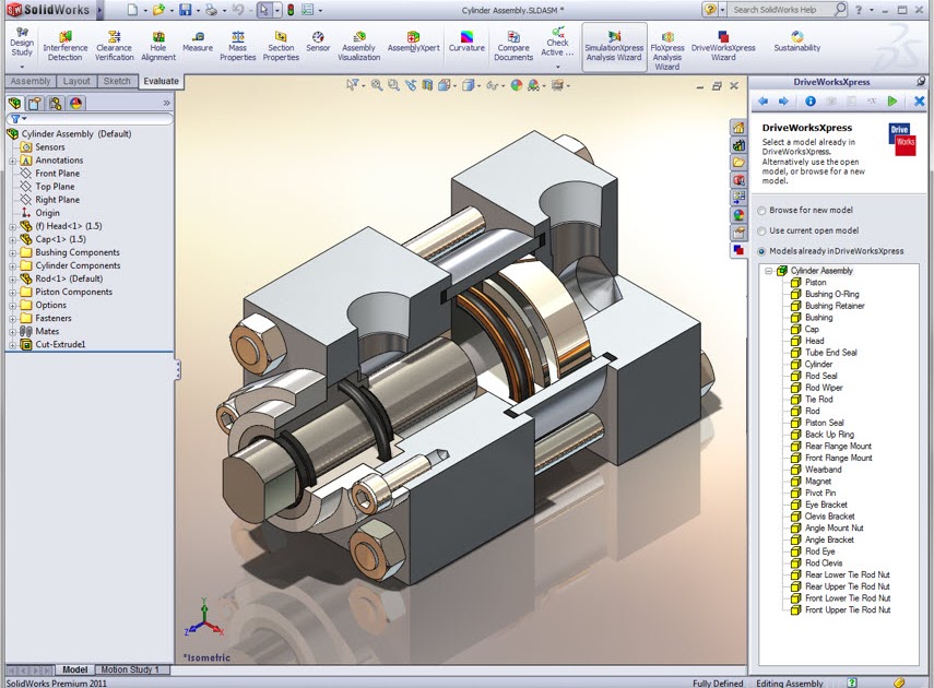 In the case of high-poly models with small triangle sizes, deformations may not be represented in this way. Instead, NetFabb will issue an exclamation point warning indicating that the 3D model needs to be fixed.
Poor-quality 3D model
Most often, the program can correct errors on its own in automatic mode, but if there are too large errors of a complex shape, this method will be ineffective. The software also provides the ability to manually correct individual triangles.
3D model conversion for 3D printing
0019 . So, with low polygonality, the 3D model will be more angular, with high polygonality, the corners will be smoothed. But do not forget that the number of polygons directly affects the "weight" of the file. For the normal operation of the slicer program (software for converting a 3D model into a control code for a 3D printer), it is desirable that the size of the STL file does not exceed 70 megabytes. Otherwise, the slicer may malfunction. The optimal file size is 5-6 megabytes. Again, there are many programs, like Solidworks, that qualitatively regulate the number of polygons in 3D models.
3D model with too many polygons
Ideally, if you yourself check the finished STL file also in the slicer, as the likelihood of unpleasant surprises during printing will be significantly reduced. It is also worth noting the fact that 3D modeling design programs (SolidWorks, Compass, Inventor, CATIA) rarely make the above mistakes. The main culprits for such situations are hardware problems.
3D models of different degrees of polygonization
Well, our article is coming to an end, we hope it was useful for you. We tried to tell you how to build 3D models for 3D printing in order to make it successful.
Finally, we want to remind you that in addition to 3D printing, we also provide 3D modeling services, which you can order by sending a letter to our e-mail, or by calling one of the phones from the “Our contacts” section.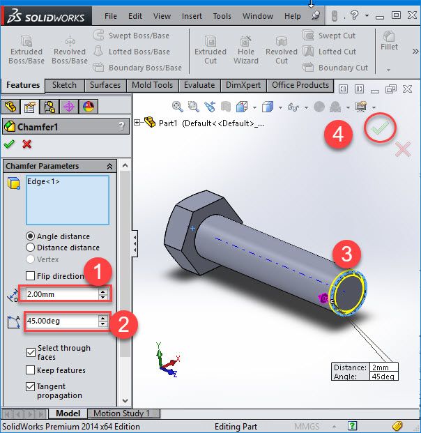 Contact us, we will be happy to help you with the implementation of projects of any complexity.
Back to home page
Different file formats for 3D printing・Cults
With the development of digital technology, 3D printing has become much more accessible today. Individuals and professionals can have their own equipment and make various print models. All that is required is a good understanding of the basic concepts, especially in relation to the respective file formats. Indeed, depending on the field and for historical or practical reasons, certain file formats are preferred for 3D printing. Here are the most common 3D printing formats and their main characteristics.
STL is short for "Stereolithography", one of the oldest file formats for 3D printing. Developed in the late 1980s, this type of format is still widely used today. It describes the surface geometry of a 3D object without displaying color, texture, or other attributes. The STL format has the ".STL" extension.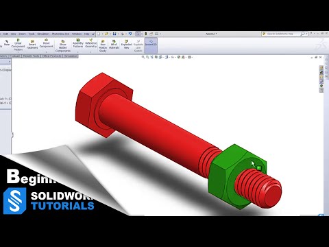 These files are generated by computer-aided design (CAD) software. Programs such as FreeCAD, Blender, MeshLab, MeshMixer, SketchUp, SculptGL, and 3DSlash can be used to edit and repair STL files.
The STL file simplifies a 3D surface into a "tessellation", a series of small triangles that increase in number when it is necessary to represent and recreate curved surfaces as best as possible. When a large number of triangles need to be used, the size of the 3D model STL file increases rapidly.
The OBJ file format is also very popular in the 3D printing industry. Its extension is ".OBJ". It has the advantage that it also encodes color and texture information, which is stored in a separate file with a ".MTL" extension. OBJ files allow the use of non-triangular faces, with one face adjoining another. They can be opened with programs such as Autodesk Maya 2013, Blender and MeshLab .
Developed in the 1990s, 3DS is a file format that stores only the most basic information about geometry, appearance, scenes, and animation.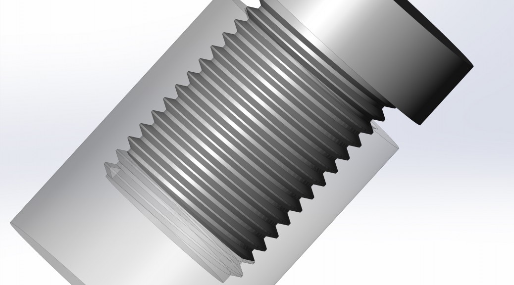 It allows you to save properties such as color, material, texture, transmissivity, etc. With the ".3DS" extension, this 3D printing file format also has the advantage that it can be read by most programs on the market, such as 3dsMax, ABViewer, Blender, MeshLab, messiahStudio, Rain Swift 3D, SketchUp, TurboCAD etc.
An SLDPRT file or its .SLDPRT extension is a 3D printing image format used by the SolidWorks CAD software. It contains a 3D object or "part" that can be combined with other parts into a single ".SLDASM" assembly file. SLDPRT files are usually opened with the SolidWorks program. However, they can be viewed using SolidWorks eDrawings Viewer, Autodesk Fusion 360, Adobe Acrobat 3D, Acrobat Pro 9 or later .
The SCAD format (.SCAD extension) is generated by OpenSCAD, a freeware modeling program used for various 2D and 3D projects. The SCAD file can be used to design 3D objects, specifying the object's geometry and positioning information.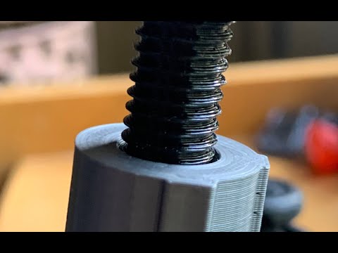 It can only be opened with OpenSCAD .
The .BLEND format is an extension used for 3D animation and projects designed with Blender's 3D modeling tool. This file type can contain multiple scenes as well as all project elements such as objects, textures, 3D meshes and real-time interaction data, sounds, lighting data, animation keyframes, display layouts, and interface settings. Please note that only Blender can work with this 3D file format.
A 3MF file (.3MF extension) is used by various design programs to save 3D models for printing. This format includes model, material, and property data compressed using ZIP compression. 3MF files also store a print ticket, a thumbnail image, and one or more digital signatures. They can be opened with programs such as Microsoft 3D Builder, Microsoft Paint 3D, Dassault Systemes SolidWorks, Dassault Systemes CATIA, McNeel Rhino, PTC Creo and Ultimaker Cura .
The .GCODE file contains commands that define how the 3D printer should print.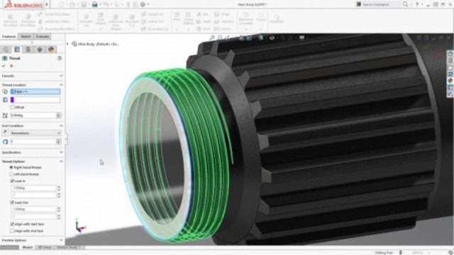 It stores instructions such as print speed, set temperature, and where to move print items. This 3D file format is created with cutting software such as Simplify3D and Slic3r. Reading can be done with Simplify3D, as well as Blaze3D, GCode Viewer and NC Viewer .
A .SKP file is a 3D model format created by SketchUp. This takes into account wireframes, textures, shadows, and edge effects. This file type is also used to store components that will be inserted into the document. Of course it can be opened with SketchUp, but also with programs like IMSI TurboCAD Pro or Deluxe, Okino Computer Graphics PolyTrans, ACCA Edificius and Trimble 3D Warehouse .
FBX is a 3D printing file format popular in the film and video game industry. Developed by Kaydara and acquired by AutoDesk, it supports geometry and appearance properties such as color and texture, as well as skeletal animation and morphs. AutoDesk will use the ".FBX" FBX file as an interchange format for its software portfolio such as AutoCAD, Fusion 360, Maya, 3DS Max, etc.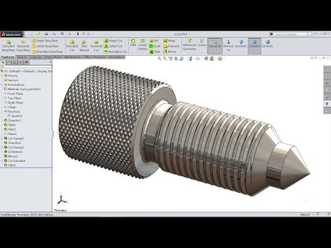
Other file types are not exclusive to 3D but are regularly used in the field.
A .RAR file is an archive containing one or more compressed files. The compression ratio of this format is greater than that of the classic ZIP compression. It is used to compress files to reduce their size for easier transportation and storage. You can extract files from RAR archive using various unpacking programs such as RARLAB WinRAR, Corel WinZip or B1 Free Archiver .
.DWG files are databases of 2D or 3D models created in AutoCAD. They consist of information about the vector image and metadata that describes the contents of the file. There are many utilities available to open this file format, including: Autodesk Auto CAD, Autodesk Inventor, Autodesk Design, Autodesk DWG, AutoDWG DWGSee, CADSoftTools ABViewer, Canvas X, Adobe Illustrator, Bricsys Bricscad, etc.
Used in 3D editing programs such as Adobe Photoshop and Autodesk Maya, the .MTL format is used to store material settings.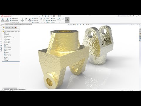 This file is stored along with another in .OBJ format and is used to describe how textures should be applied and the 3D coordinates they should be applied to.
This page has been translated using machine translation. Suggest the best translation
Previous
ShareNext
Similar publications
Since their invention, 3D printers have proven that printing many objects is much more efficient than conventional manufacturing techniques. However, calibration is required for optimal performance when printing 3D parts. Many 3D printer owners find this procedure tedious and time-consuming. However, it is much easier than it seems if you know the right tips on how to do it. Cults3D presents the various steps you need to follow in order to successfully calibrate your printer.
Read more The plate is one of the most important parts of a 3D printer. For optimal printer performance, it must be properly cleaned after each print session.