3D printing systems support
Support : 3D Printing Systems
Support : 3D Printing SystemsHow can we help you today?
Enter your search term here...
Knowledge base
UP 3D Printers
General 8
-
What is support material, what is it made of and why do I need it?
-
How does the UP 3D printer's print head (Extruder) work?
-
How do I stop my model from lifting/warping?
-
What is 'warping' and why does it happen?
-
Air Printing
UP Mini 4
-
UP Mini User Manual
-
Getting Started - First print
-
3D printed parts for UP Mini 1
-
Upgrade for UP Mini 1
UP Mini 2 5
-
UP Mini 2 User Manual
-
Getting Started - First print
-
3D printed parts for UP Mini 2
-
UP Mini Maintenance and Support Videos
-
How to replace the Extruder Rainbow Cable to the Print Head
UP Plus 2 5
-
UP Plus 2 User Manual
-
Getting Started - First print
-
3D Printed Parts for UP Plus 2
-
UPgrade for UP Plus/2
-
UP Plus 2 Maintenance and Support Videos
UP Box 6
-
UP BOX User Manual
-
Getting Started - First print
-
3D printed parts for UP Box
-
Upgrades for your UP Box
-
UP Box Maintenance and Support Videos
UP300 2
-
UP300 User Manual and Quick Start Guide
-
3D printed parts for UP300
X5 0
Filament 2
-
PLA Tips and Tricks
-
3D Printing with Nylon filament
Software - UP Studio 7
-
Where can I download UP 3D Printer software?
-
What version of software should I download?
-
How to check what version of UP Studio your currently using?
-
Resetting the SD Card using UP Studio
-
How to Connect to your WiFi 3D printer
Software - UP! 5
-
How to install printer drivers in Windows?
-
How to disable signature driver enforcement in Windows 8.
1?
-
How to adjust the support angle in the UP software.
-
How to update my printer's ROM? [UP Plus/Mini]
-
Model out of print range
3D Scanners
ScanMaster Body 2
-
Installation Manual
-
Kit Assembly Instructions
ScanMaster Plus 1
-
ScanMaster Plus Manual
Emblaser 2
Getting started 1
-
Emblaser 2 Manuals and documentation
LightBurn 1
-
Getting Started
Materials 2
-
How to import and create material profiles or databases - Lightburn
-
How to import the material database - LaserWeb
Help Desk Software by Freshdesk Support Desk
What are supports in 3D printing? When and why do you need them?
What are support structures in 3D printing? Depending on the technology you use to produce parts, you may need to print support structures to maintain part geometry.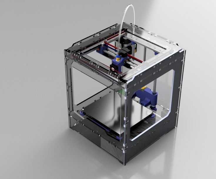 This article covers what support structures are in 3D printing, when they’re needed and how supports may affect the quality and price of your part.
3D printing builds parts layer by layer, so there always has to be a previous layer to build upon. Depending on the specific 3D printing technology and complexity of the 3D model, you may need to produce your part with support structures.
When deciding which 3D printing technology to use, it’s essential to consider support structures and how they affect the quality and price of your part. As well, support structures will have an impact on your part’s surface finish. Removing supports from a part often results in blemishes or surface roughness.
This article defines what support structures are for 3D printing, how they’re implemented for each technology and how using supports can affect your choice of manufacturing technology.
How do supports work for FDM 3D printing?
Fused deposition modeling (FDM) extrudes a metal filament onto a build surface along a predetermined path.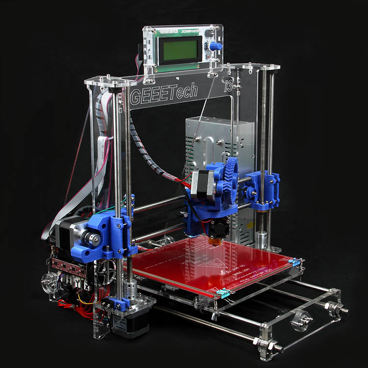 As the material is extruded, it cools, forming a solid surface that provides the foundation for the next layer of material.
With FDM printing, each layer is printed as a set of heated filament threads which adhere to the threads below and around it. Each thread is printed slightly offset from its previous layer, allowing a model to be built up to angles of 45 degrees. This way, prints can expand beyond the width of preceding layers of filament.
When a feature is printed with an overhang beyond 45 degrees, it can sag enough to potentially ruin the print. This is when you need support structures.
Depending on the degree of the overhang, your FDM part may need supportsWhen do you need support structures for FDM?
Let’s imagine you have to 3D print models of the letters Y, H and T.
An FDM printer can easily print the arms of the letter Y without requiring support structures.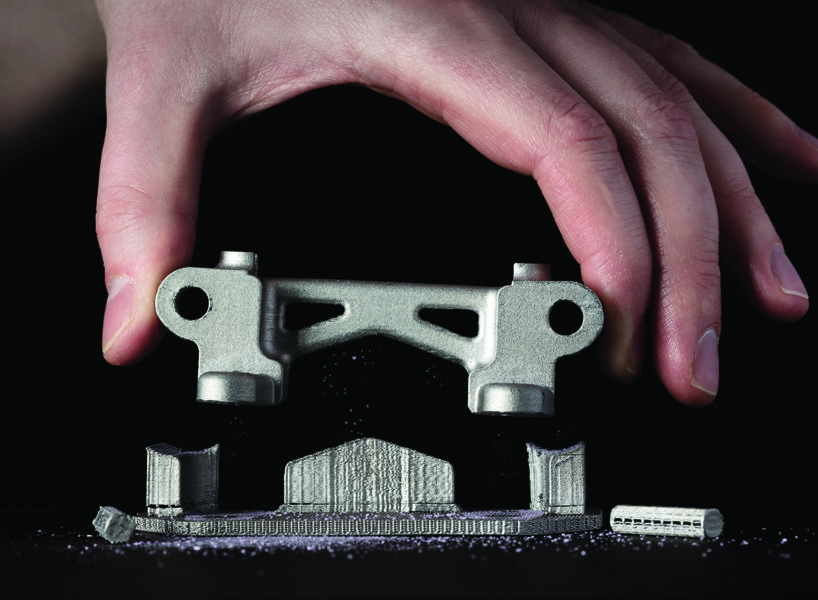 Even though these features are outstretched, they don’t extend past 45 degrees.
The letter H, on the other hand, is a bit more complicated. If the center bridge is under 5 mm, it can be printed without support or any sagging. Support is required if the bridge exceeds 5 mm. In the example shown here, the center bridge is over 5 mm, so it’s printed with support structures.
The letter T requires support for the top features extending from either side of the model. There is nothing for these out arms to be printed on and the material will fall down without supports.
The image below illustrates these three examples. The support material is shown in light gray.
An illustration of when you need support structures for FDMHere is how these models look when printed. The second image shows the result of the T printed without support. The surface has significant sagging and will require a lot of post-processing to clean up.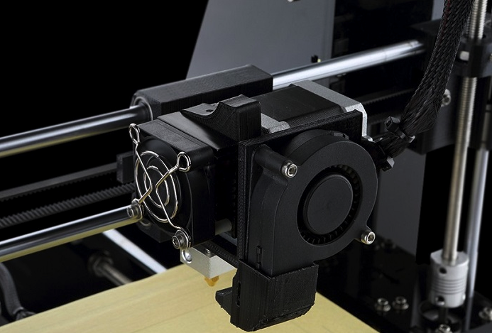
What is bridging in FDM?
In some cases, there is an exception to this overhang rule.
Hot material can be stretched short distances between two points of a print. This method is known as bridging. Bridging allows parts to be printed without support materials and with minimal sagging. If a bridge is over 5 mm long, support structures are required if you’re hoping to achieve an accurate surface finish.
Curious about the price and material options for FDM?
Explore our FDM services Get a free, instant quote today
What are the disadvantages of support structures in FDM?
The potential need to use support structures is one reason why FDM is not always the right technology for your application. One of the limitations of using supports in FDM printing is that post-processing is then required, which results in marks or damage to the surface in contact with the support materials.
Another issue is that layers printed on support structures will be less even because the supports won’t be stationary like solid layers of extruded filament. On top of this, supports can be difficult to remove from small, intricate features. This bit of post-processing could break your model.
Furthermore, having to print support structures adds to the cost of FDM. Supports require additional printing material that later needs to be removed, creating more work (and waste) for the operator. More materials and more human intervention equal higher costs.
An FDM-printed puzzle piece with supports removed to show surface roughnessHow much support material do you need for your FDM print?
The amount of material you’ll need for support structures will ultimately depend on the design. If you’re printing a replica of the Gateway Arch in St. Louis, for instance (like the example below), you’ll only need a limited amount of support placed in the correct location to allow accurate printing.
Now, if you’re printing a “ball in a cube” (shown below), you’ll need quite a lot of support material, which means a sizable amount of removal time as well.
Removing the supports in this example is complex and involves getting rid of each support element with needle-nose pliers while attempting to limit the damage to the surfaces surrounding the supports. Sanding or smoothing these surfaces after support removal presents another difficulty.
However, without support materials, this model can’t be printed with FDM, unless you want to compromise on quality and accuracy. In this case—despite the added cost and print time—the additional support material used is essential to being able to print this design.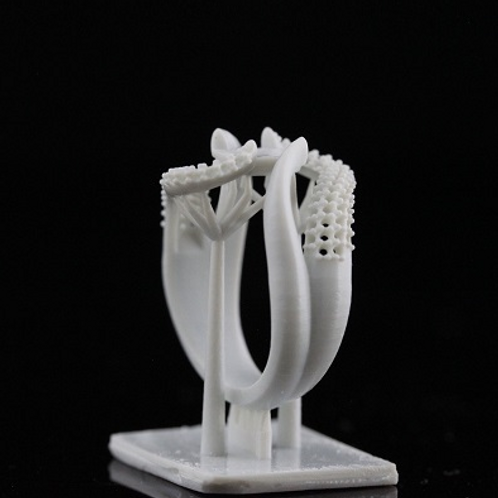
What are the two types of support structures for FDM?
FDM 3D printing uses two types of support structures. The most common (and best suited for most FDM partS) is a sort of flat accordion or lattice structure. The other is “tree-like” support, which has less contact with the print surface and can leave you with better surface finishes after post-processing. Though it’s less common, the latter is much preferred by some operators.
The FDM printer operator will generally specify the type of support that best suits your application and minimizes the cosmetic impact it’ll have on your design.
These are two different types of support structures: According (left) and tree (right)Are there dissolvable supports for FDM?
Finely-tuned printers with two print heads can print support structures with a dissolvable material that doesn’t tear away from the part. Instead, you can dissolve this material in a chemical solution that won’t adversely affect the printed model.
This results in a better surface finish where the support is in contact with the main material, however, it can be expensive and time-consuming.
All industrial FDM machines are equipped to use dissolvable support materials. For instance, you have the Ultimaker 3, which can print PVA that dissolves quite easily post-print.
Do you need support structures for SLA & DLP 3D printing?
Stereolithography (SLA) and Digital Light Processing (DLP)create 3D printed objects from a liquid (photopolymer) resin by using a light source to solidify the liquid material.
Depending on the exact type of printer, you have two main methods of producing a model. Certain printers pull a model out of a vat that contains liquid material, solidifying it via a light source through a translucent window at the bottom (bottom-up). Others submerge the model into the liquid as the top layer is tread by a light source from the top (top-down).
To make sure that the prints adhere to the print platform and don’t float around in the vat, SLA and DLP printers almost always use supports.
Support structures from these printers look like thin ribs, with only small tips actually touching the model to save material and printing time. The number of supports, their location, where they touch the model and the structure are calculated by the software and are dependent on the shape, orientation and weight of the part being printed.
SLA and DLP are some of the most accurate technologies, capable of printing even the smallest and most intricate objects with accurate detail. With proper post-processing, printing with support does not impact the quality of the part.
An SLA print with support structuresHow do you remove support materials from SLA & DLP prints?
First, Isopropyl Alcohol (IPA) is used to wash liquid resin off your completed parts. Support structures can be either broken off the surface of the model or removed using pliers. The spots where the support was in contact with the object are then sanded to remove any remaining marks.
Removing support structures from an SLA printCurious about the cost and materials available for SLA/DLP?
See all SLA/DLP materials Get a free, instant quote today
Do you need support structures for material jetting?
Material Jetting (Stratasys PolyJet and 3D Systems MultiJet Modeling) technologies are similar to inkjet printing, but instead of jetting drops of ink onto paper, these 3D printers jet layers of liquid photopolymer onto a build tray and cure them instantly using UV light.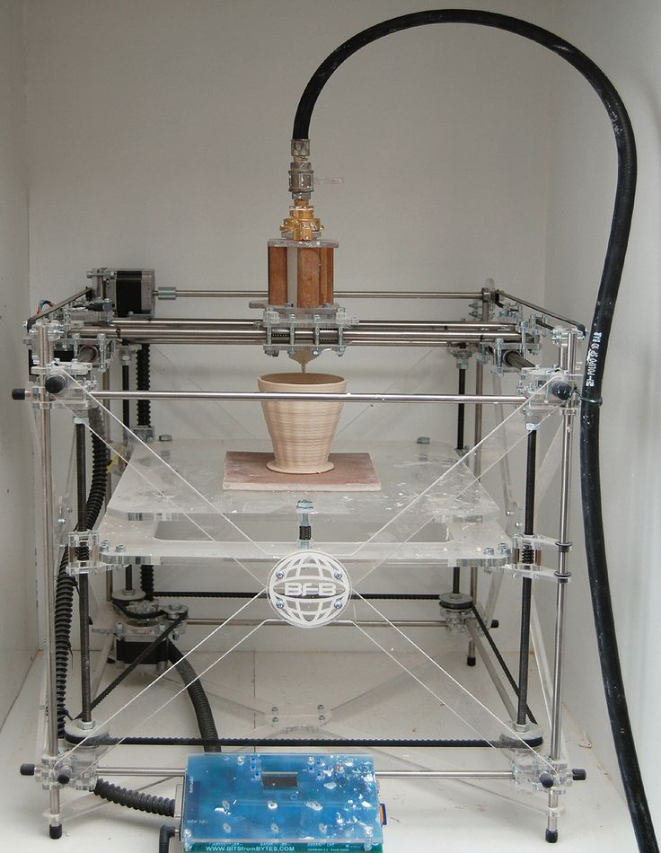
These printers require the use of support material in all cases where there are overhanging features, regardless of the angle. Supports are either water-soluble or are removed during post-processing using plyers, water jetting, ultrasonic baths and sandblasting.
Unlike FDM, supports for these technologies are in no way detrimental to a part’s cosmetic appearance, surface quality or technical properties. After proper post-processing, it’s practically impossible to distinguish where support materials were removed from your part.
Removing water soluble support material from a Polyjet (material jetting) printerPost-processing for material jetting involves power tools like waterjets and sandblasters, and using these tools may damage or bend the more intricate features of your model. We recommend that you follow our Material Jetting rules to avoid these sorts of issues. In fact, you may want to opt to print your parts using SLS if your model has intricate features and thin wires.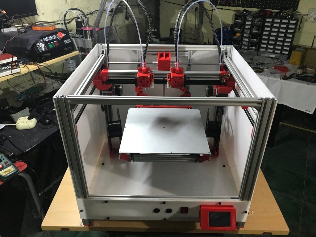
Do you need support structures for SLS?
Selective Laser Sintering (SLS) 3D printers fuse powdered material in a chamber using a laser.
For SLS, there’s no need for support structures since the powder acts as a form of support when the object is built up layer by layer. This gives a lot of design freedom but also generally increases the cost and time to print a part. SLS requires time for the build chamber to cool down and cleaning the print requires a multi-step finishing process, including removing unfused powder, typically with an air gun.
When printing with SLS, the unfused powder surrounding the print functions as a natural support structure that's also easy to removeCurious about the cost and materials available for SLS?
See all SLS materials Get free, instant quote today
Do you need support structures for binding jetting?
Binder jetting is similar to SLS in that the printer uses thin layers of powdered material to build up an object.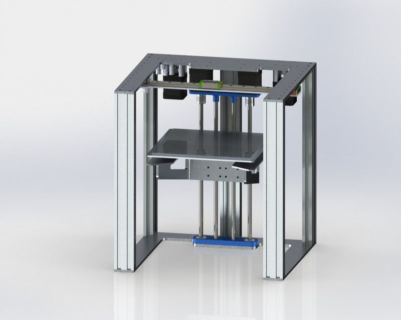 Instead of using a laser to sinter layers together, however, binder jetting printers use a binding agent extruded from a nozzle to bind the powder together.
Similar to SLS, there’s no need for support structures with binder jetting since the powder supports the object as it’s built. As well, you have to clean and post-processing the print over several steps, including removing unfused powder with an air gun or another tool.
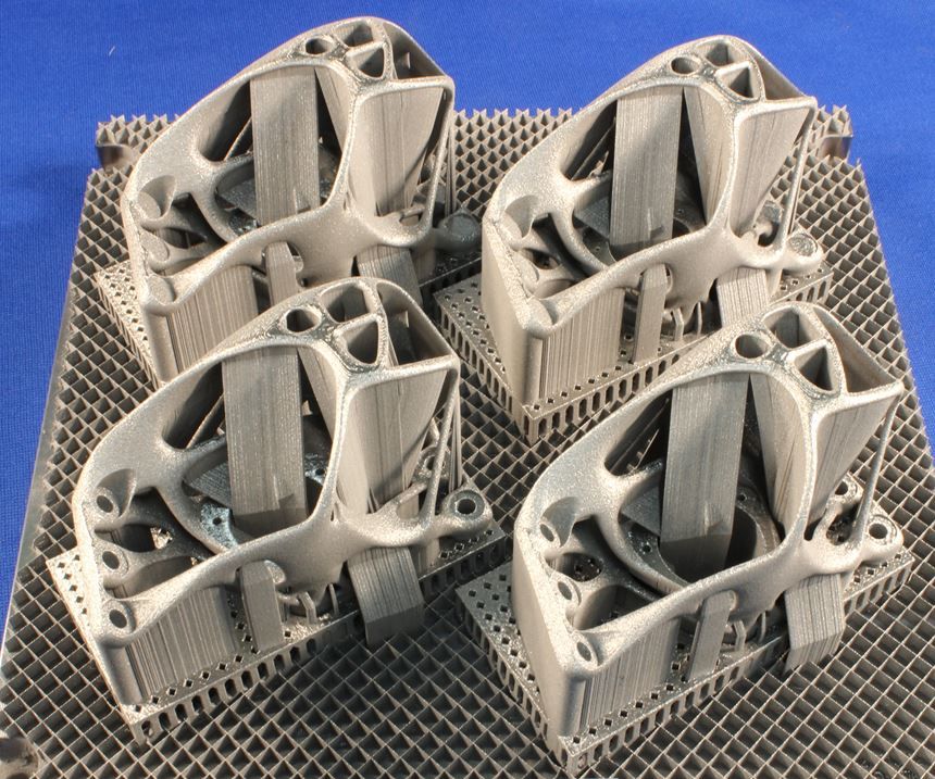
Unfused powder being removed from a binder jetted printDo you need support structures for metal 3D printing?
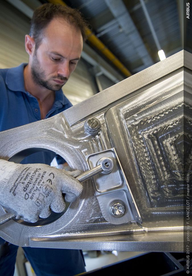
Metal 3D printing technologies use support structures to keep models fixed to a base plate during the building process. However, overhangs with an angle greater than 35 degrees can be printed without support.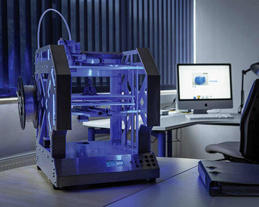
When you do need supports for metal 3D printing, it’s important to ensure that they are easy to access, or else it’ll be challenging and maybe even infeasible to remove them during post-processing.
Using supports won’t impact the overall quality of your part, and with the proper post-processing methods, you can remove all marks from the printed model.
These metal prints, which are still attached to the print bed, still have visible support structuresHubs' top tips & tricks for optimizing 3D printing with support structures
Whether or not you need to use support materials for your specific application, it’s important to know the best practices for this aspect of the 3D printing process.
-
Support structures will generally affect the cosmetic appearance of a part, so you’ll need to rely on post-processing to improve the surface finish after removing supports.
 Material Jetting is the exception to this rule.
 -
The more support structures you print, the more complex a design can be for certain 3D printing technologies. You can optimize the amount of support material you use by addressing part orientation and part accuracy (among other design and manufacturing factors) to lower the cost and print time.
Which 3D printing technologies require support structures?
At the end of the day, this is the most essential question. The table below summarizes whether support is required for each of the 3D printing technologies we offer at Hubs.
| 3D printing technology | Do I need support structures? |
|---|---|
| FDM (desktop & industrial) | Depends on model geometry |
| SLA & DLP | Always |
| Material Jetting | Always (dissolvable) |
| SLS & MJF | Never |
| Binder Jetting | Never |
| Metal 3D printing | Always |
Ready to transform your CAD file into a custom part? Upload your designs for a free, instant quote.
 Get an instant quote
What is support in 3D printing?
One of the most frequently asked questions when working with clients is “What is 3D printing support?”. In this section, we will clearly show what is commonly called support and what types of support exist at a given point in time.
Support material (supportmaterial) is an auxiliary material used in 3D printing to build complex objects and increase the quality and stability of construction. Without the use of support, it is impossible to 3D print models with cavities, overhanging structures, complex detailing, thin walls or ceilings, and other complex elements.
Simply put, support serves as a kind of temporary foundation for the printed product. Layered construction assumes that each next layer of the product relies on the previous one. In the case when the design of the product does not provide support under the first layer in one place or another, support comes into play.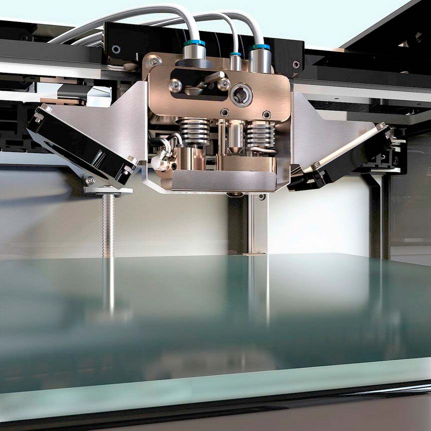
It must be understood that the removal of supporting structures is one of the most difficult types of work.
Therefore, this article was written, fully explaining what support structures are and why they are needed in 3D printing.
How to determine where support is needed?
This is done automatically by the software supplied with all professional 3D printers. You just need to upload a file in STL format, and the program will independently calculate where the use of auxiliary material is necessary for high-quality construction. It is worth noting that most software also allows the user to edit the number and location of auxiliary structures. The software is directly related to the capabilities of a 3D printer and will automatically show you where support is needed and where it is not.
In addition, the program calculates the amount of auxiliary material needed before printing.
If we do not agree with the automatic calculation of supports by software for a three-dimensional printer, then software comes to our aid where supports can be placed manually. The picture shows an example of manually building supports in the AutoDesk MeshMixer program.
Types of support materials
Soluble
There are 2 types of soluble auxiliary materials such as HIPS and PVA. These types of plastics are used for printing supports in complex models, where high quality of the resulting product is an important component.
Each type of plastic has its pros and cons.
For example, HIPS can be used both as a base material and as an auxiliary. This plastic is soluble in limonene, so it is excellent for printing supports, where the main plastic is ABS, since they do not interact with each other. It also has its drawbacks - this is the high cost of limonene.
PVA, on the other hand, is used exclusively as an auxiliary material. It dissolves well in water and is only compatible with plastics where PLA is the main material. But there are two important differences from HIPS: the high cost of the material and the more simplified post-processing of the finished product.
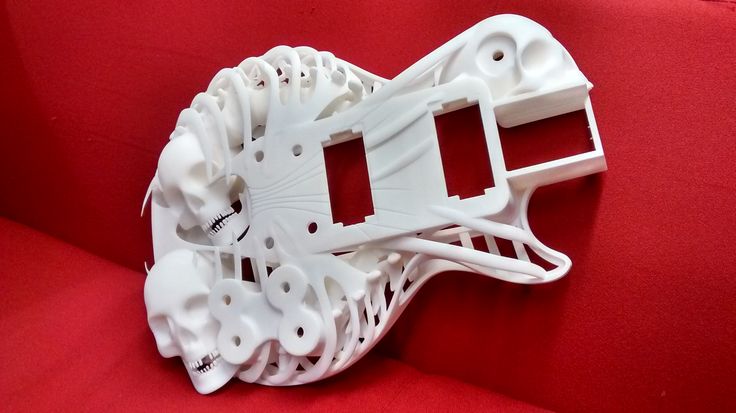
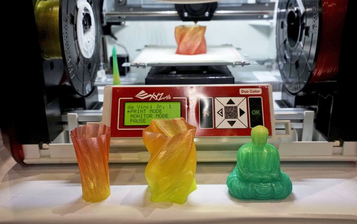
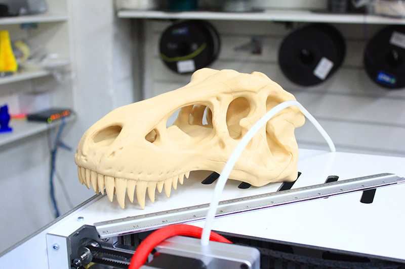
3D printer in the process of printing with support structures.
The finished product immediately after 3D printing.
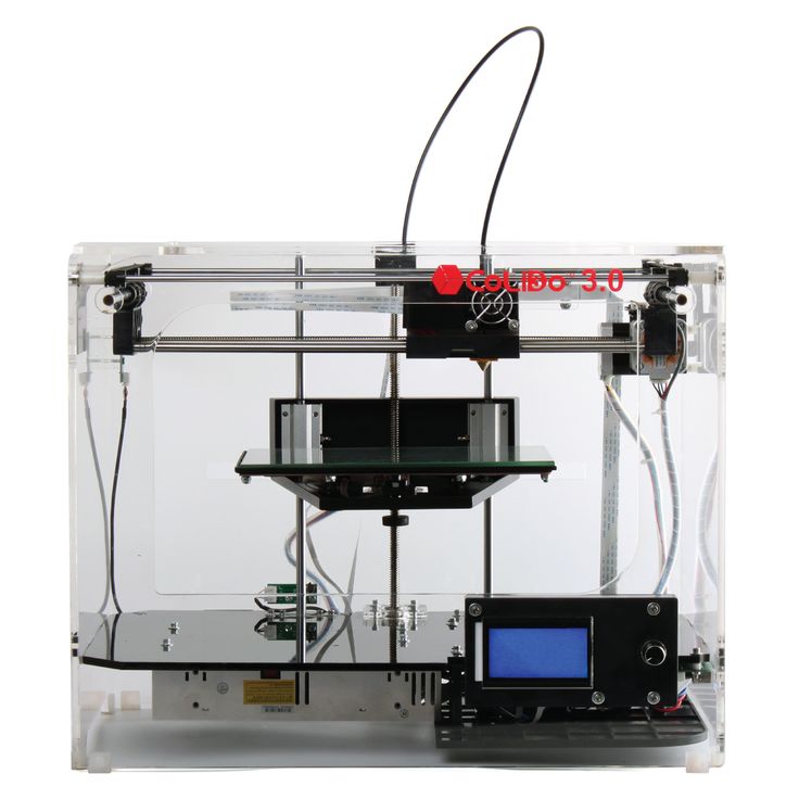
Detail after washing out the supporting structures.
Mechanically removed
Excess material is broken off, sawn off, scraped off. In this case, the support is the same material from which the model itself is built. But, in order to facilitate its subsequent removal and reduce the consumption of model material, the support is built more “sparsely” compared to the object itself. It has a much lower density and strength, only sufficient to temporarily support the weight of the object being grown.
Fused
Melts and flows out with slight heating (much lower than the deformation temperature of the main product). Usually has a wax base. Advantages: delicacy, accuracy of application. Used in photopolymer and wax 3D printers of the ProJet series by 3D Systems.
Powder support
Separately, it is worth mentioning powder 3D printing technologies. Here, the same material acts as auxiliary and main. However, that part of the powder that was "auxiliary", after cleaning, can be reused as the main material. Due to this, such technologies are practically waste-free. The only exception to the rule is metal 3D printing. When printing with metal, metal shrinkage must be taken into account. In order for your part not to twist or warp during the printing process, it is necessary to fix it with supports.
Tags: 3D printing, 3D printer, 3D printers, Additive technologies, Parts, Inventions, Body parts, support material, support
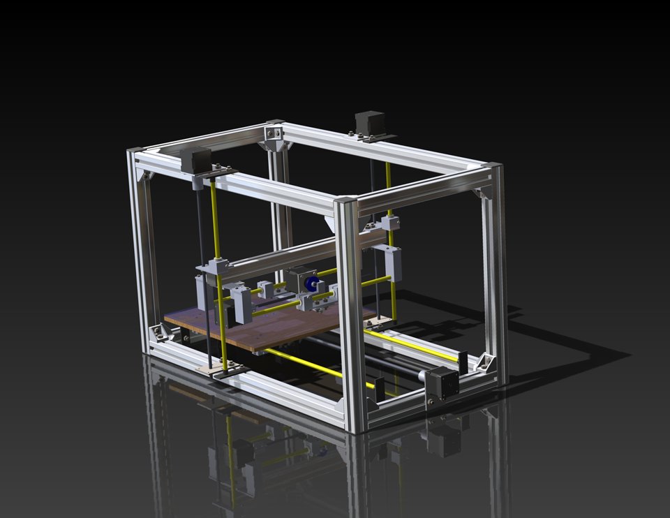
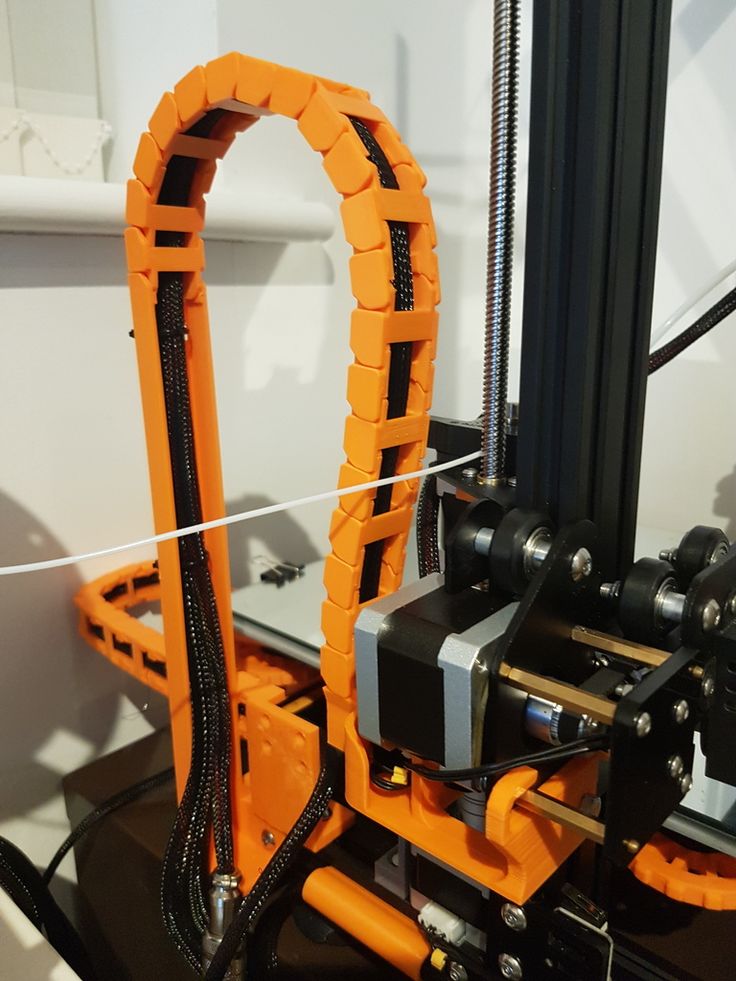
Automation in FDM. What prevents us from printing 24/7?
The 24/7 production of parts using FDM technology is hampered by the high labor intensity of each action taken, as well as the need for an operator to be near the printer.
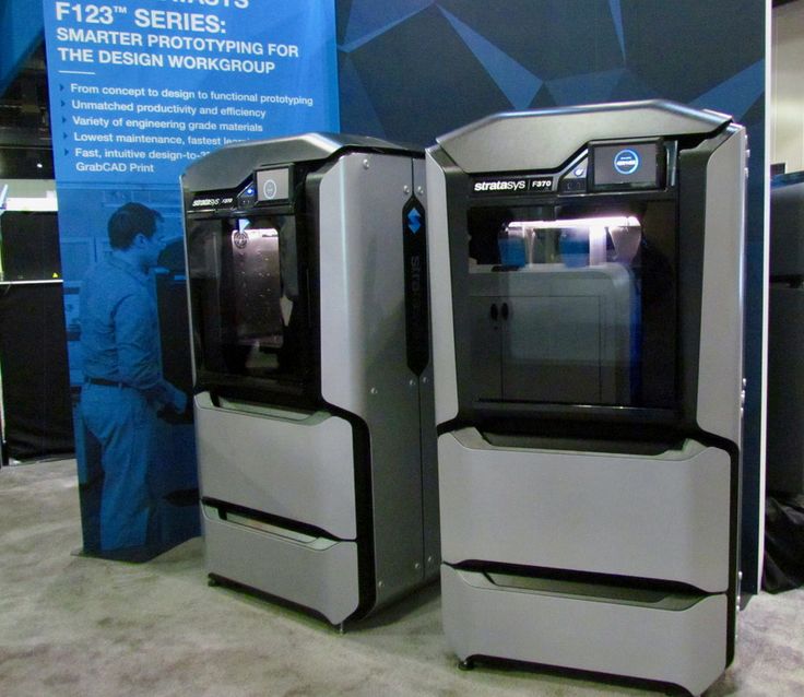
If we compare the most common modern FDM 3D printers on the Russian market with ordinary office printers, then in terms of automation level they are closer to a manual printing press than to an MFP.
The FDM 3D printer will be idle if the operator has not removed an already finished part from the desktop or if he has run out of material. In the event of a technical malfunction, the operator spends more time finding the malfunction itself than fixing it.
If the production is small (up to 10 printers, up to 1000 parts per month), then these problems are not noticeable. Typically, such a pilot plant is run by a single specialist who has a thorough knowledge of the printers entrusted to him, but even an experienced print specialist cannot work 24/7 and produce a large product range with high quality if it changes frequently (for example, in 3D printing service farms).
If a company needs to increase the productivity of its 3D printing department, this is usually followed by an increase in the staff of operators, an increase in the number of printers, an increase in technical costs (manufacturing defects, technical and technological downtime).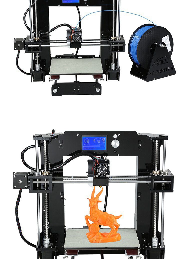 When deadlines are pressed, there is a need to work first in two shifts, and then in three.
Over the past three years of running serial orders at our St. Petersburg 3D printing services farm, we have identified the most expensive operations in terms of productivity and labor intensity:
1. Material change - requires operator presence.
2. Preparation of the working area, calibration - in case of operator error, it leads to marriage, time is lost for reprinting.
3. Media Inspection - At the end of the printing process, the printer is either idle or the product is rejected.
4. The printer is idle until the operator removes the product from the worktable.
5. The printer is idle while the operator is looking for a problem or waiting for a response from technical support. The problem applies to printers whose manufacturer does not provide detailed technical documentation.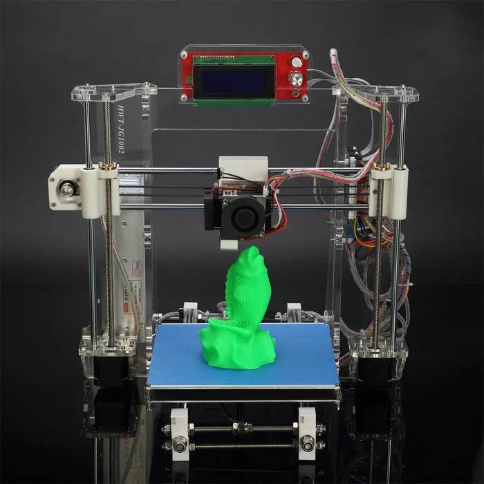 A large fleet of printers requires a dedicated service engineer.
6. The increase in the number of orders for production requires the appearance of a technician to solve routine auxiliary tasks (for example, replacement and control of the availability of material), otherwise the workload on operators increases, rejects become more frequent, equipment is idle.
7. Delegation between operator shifts often results in overproduction of parts or loss of order information. To combat this, investments in accounting systems or the hiring of additional administrative staff are required.
It follows from this:
2. An increase in the number of orders is a non-linear increase in the labor intensity of production.
3. Staff expansion - growth of non-production costs.
4. Increasing the labor intensity of production - increasing the terms of product readiness.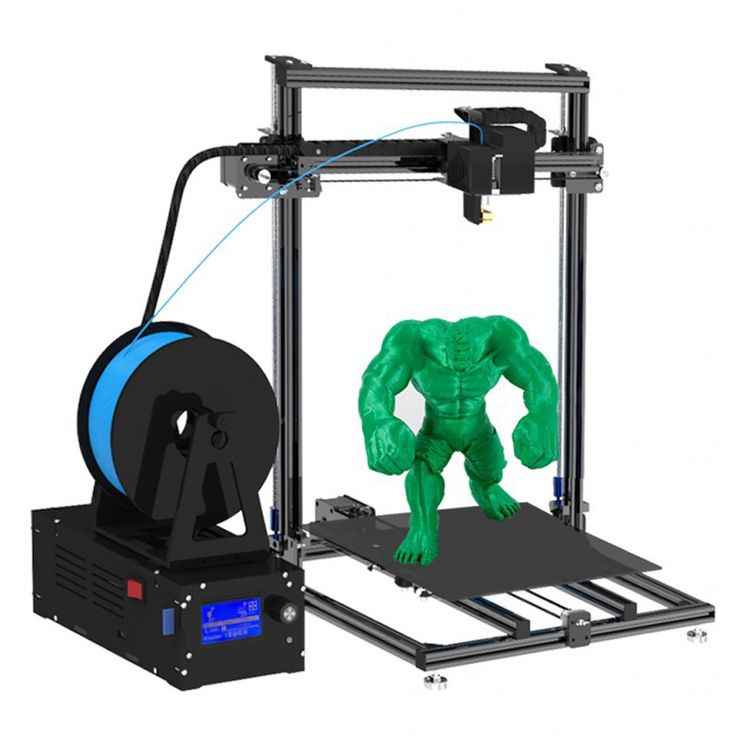
5. Lack of automated accounting tools - increased costs for marriage and re-sorting.
6. Shift schedule - increased staff and increased costs for marriage and regrading.
7. Round-the-clock work - increase in staff, decrease in the level of responsibility for quality.
Thus, FDM 3D printing is scaling at a significant cost and is accompanied by an increase in staff, an increase in payroll costs, and a non-linear increase in production and administrative costs. Added to this are the difficulties with organizing in-line printing, the lack of analytics and statistical data on production, material consumption, and data on equipment loading.
The reason is the lack of technical and software automation of routine actions in FDM printing.
To solve the above scaling problems, in the spring of 2020, we began the development of an automated FDM 3D printing complex.
The following development goals were identified:
1. Automate the routine removal of finished products and material replacement, eliminating the need for the constant presence of the operator near the printers.
2. Have complete information about the technical condition of the printer without visual control and operator presence.
3. Ensure the scalability of production without increasing non-production costs.
4. Reduce the labor intensity of production planning, control and accounting of printed products.
5. Reduce the risk of technical failures and downtime for service and recovery.
6. Ensure compatibility with the most common thermoplastics and composites and reduce changeover downtime, reduce downtime between operations.
7. Collect and analyze data on the printing process and equipment status, display analytics not only for production, but also for administrative staff, including material consumption and manufacturing defects.
8. Predict project deadlines as accurately as possible by using real time to print the first samples in a batch.
9. Implement a management system with two-way exchange with third-party CRM (Bitrix24) and accounting systems (1C: UNF) for end-to-end analytics of the effectiveness of investments in the additive unit.
In this article, we present a comprehensive solution to the task of automating FDM 3D printing - the Redfab additive manufacturing hardware and software system.
Redfab 3D printer solves existing problems in the following way:
1. Automatic Selective Feeding and Media Change
The system allows you to selectively feed, remove, cut and rewind media autonomously or at the operator's command. Up to 5 D300 2.25 kg spools or up to 8 D200 1 kg spools are simultaneously connected to each print zone. Main extruder and sub extruder each have 4 slots for 1.75+/-0.15mm bar. Having loaded the coil compartment once, the engineer may not return to the issue of refilling the material for a long time, up to 8 days of continuous printing at a flow rate of ~50 cm3/hour, or 4 days at a flow rate of ~100 cm3/hour.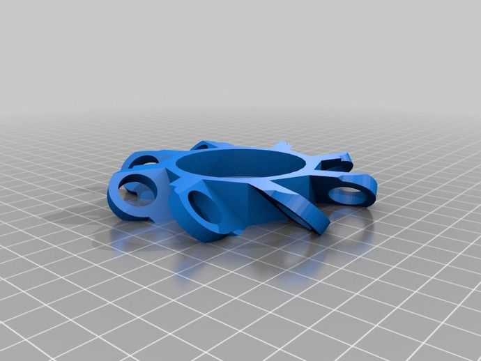 At the end of plastic on the coil, the system automatically switches to the next one. This uses the media specified in the print job.
2. Automatic ejection of finished products
The part is printed on a film pressed against the work table by vacuum. After printing is completed, the film is pulled through the cooling system, the part is separated and dumped into a container. After the finished batch is reset, the printer autonomously starts the next print. Since the parts are ejected from the hot table, reheating is not required.
3. Automatic table plane calibration
Calibration of the print plane by 4 points and the table by 20 points with correction factors entered into the control system (MESH). The milled table has no internal stresses, as it undergoes a heat treatment procedure.
The table is thermally decoupled from the power frame of the printer, due to which it does not warp when heated up to 140°C.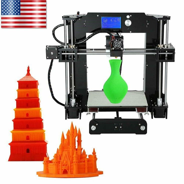
Calibration is performed automatically without the participation of a specialist.
4. Automatic print queue
The user sets the print parameters, the control system automatically forms a queue of projects and jobs for production according to the parameters specified by the user. The availability and availability of material, nozzle parameters, production priorities are taken into account.
5. Automatic service operations
The control system detects failures and accidents based on the readings of the sensors, and then attempts to independently maintain and restore the printing process in cases where it is possible. A well-thought-out control system prevents false failures and gives the user flexibility in making decisions. The printing process will not be stopped if a failure occurs in the auxiliary system. Thus, the complex will try to complete the current print, after notifying the user.
6. Easy Maintenance
Modular design, quick-detachable extruders and easy access to all equipment components allow quick and easy periodic maintenance. You can write a request to technical support directly from the control system. When requested and authorized by the user, our technical support service can remotely connect to the control system and both carry out a complete diagnosis of the system settings and track the printing process itself thanks to the built-in video camera. Since we produce most of the components ourselves, we are ready to promptly provide the customer with spare parts.
The Redfab 3D printer is equipped with the advanced control system, which allows real-time analysis of production processes, which is indispensable for assessing the current work and making decisions on the development of FDM printing. 1. Statistics, accounting and analysis carrying out maintenance with the output of reports and comparison of periods.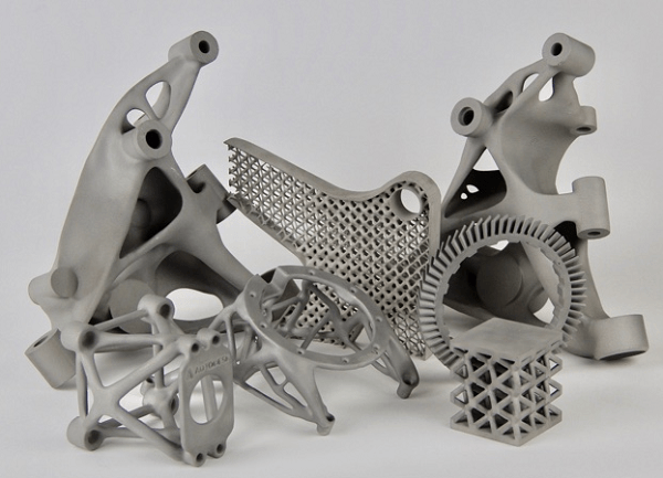
2. Production time control
The system allows you to visualize the production time on the Gantt chart and calculates the order readiness for delivery based on the actual printing time of the first copy of the print job. This allows you to predict the completion time of the entire project with high accuracy.
3. Remote monitoring of the printing process
The user gets access to the video stream from the camera located in the working area. At the beginning and at the end of printing, a control picture is taken, which allows you to track the readiness of the product and the absence of defects. In the future, we plan to automate this aspect of work, using vision algorithms.
4. Access control and accounting
Authentication system, setting group rights, setting roles (trainee, technician, operator, administrator, technical support), logging user actions in the control system.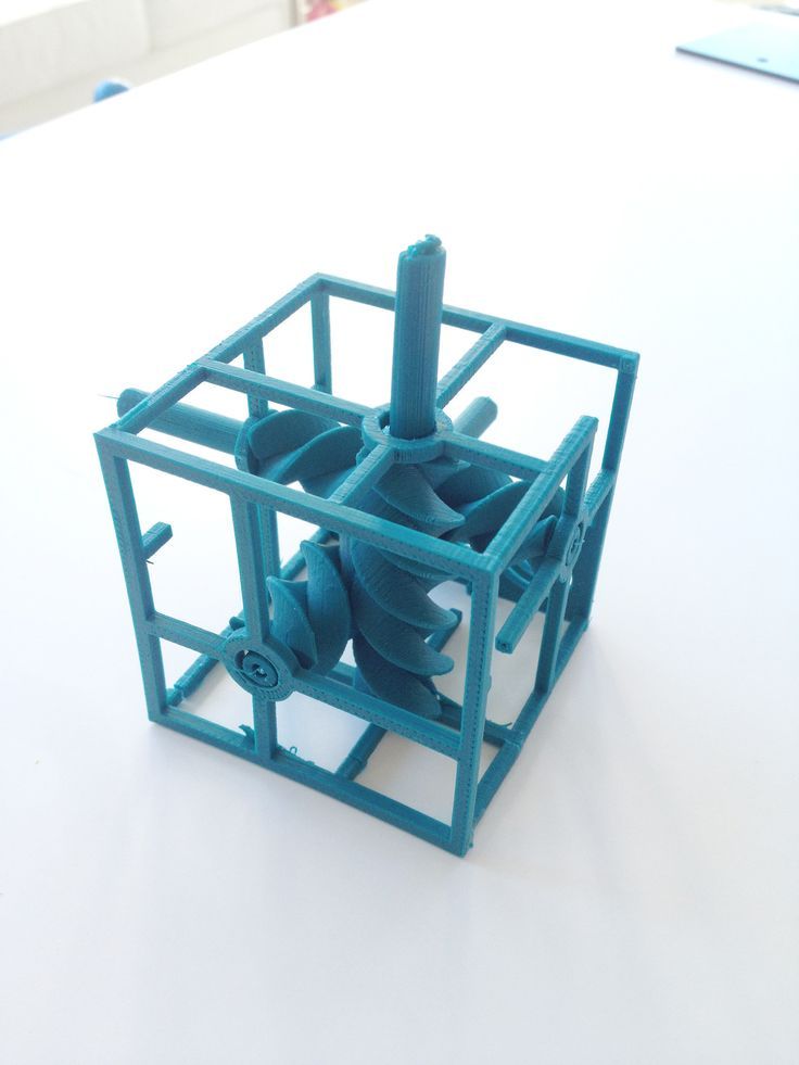 This functionality allows you to ensure that the system is closed to third parties and restrict access to production and accounting data in accordance with the client's privacy policy.
| Parameter name | Value |
|---|---|
| Print area (X/Y/Z), mm | 250*430*250 |
| Number of printing areas in 1 complex, pcs. | 3 |
| Number of extruders per print area, pcs. | 2, direct, quick release |
| Maximum extrusion temperature, °C | 450 |
| Maximum air temperature in the active heat chamber with forced circulation, °С | 80 |
| Maximum heating temperature of the working table, °С | 140 |
| Parts Cooling Systems | Material cooling at nozzle exit. Cooling of the layer over the entire print area. |
| Performance at maximum practical printing speed, cm 3 / hour | up to 150 (for ABS Standard Filamentarno) |
| Supported file format | gcode, slicer of user choice |
| Data interfaces | LAN Ethernet, USB, Wi-Fi |
Our equipment is running 24/7 on our own 3D printing farm, so we can confidently provide you with a 2 year warranty on your Redfab 3D printer.
To calculate the profitability of purchasing our printer, we suggest using the calculator on our website www.redfab.ru.
The calculator allows you to estimate the rate of return on investment.
For large-scale productions (from 20 units of 3D printers), we recommend considering a one-time purchase of 4 units of Redfab printers at once for leasing at a special price.

Learn more