3D printing setup
How to set up your first 3D printer
For the last 10 years or so, 3D printing has been a popular buzzword. Proponents have long hyped the idea that if you think of something new or break something you own, you can just push a button on your computer and print a new one in minutes. Perhaps these ideas were overblown at one point, but after finally obtaining a printer following years of skepticism, it seems that many of the early issues with these devices have been worked out. I use mine all the time, for projects from printing a replacement part for a lamp, to crafting the body of a small rocket-launching robot.
Make your choice
If you search the web for “3D printer” you’ll find a variety of models with prices ranging from less than $200 to well over $1,000. There is, of course, some difference in quality among printers at each price level, and you’ll want to consider specifications such as resolution, the materials it can print with, print speed, and print area, which determines how big of a print you can make.
The Ender 3, which costs a little more than $200, is a popular choice for its generous 220-by-220-by-250-millimeter print area, while the Prusa i3 MK3 is a well-respected printer that’ll run you about $1,000. Personally, I purchased a Monoprice Select Mini 3D Printer V2, which is an exceptionally popular small-budget printer. It’s pretty basic, features-wise, with a relatively small 120-by-120-by-120-millimeter print area, but it cost less than $200 and worked extremely well out of the box for me.
Getting started
After unboxing your printer, you’ll need to level the bed, which simply means adjusting screws at each corner of the printing surface to ensure it’s a consistent distance from the tip of the extruder—the part that prints. More capable printers often feature an auto-leveling function, but the Monoprice Select Mini does not.
Instead, I had to move the extruder nozzle—the tip of the extruder assembly that molten filament flows out of—to positions near the four bed adjustment screws and turn them until it was 0.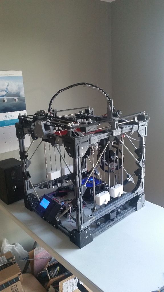 05 millimeters above the bed. The manual suggests measuring this by attempting to slide a piece of paper underneath, and says that when it slides with only a slight amount of resistance, the adjustment is correct.
This method seemed a little haphazard, so I turned to a set of feeler gauges. It worked well and I didn’t have to adjust anything again for several months, but if you don’t have these gauges handy, the paper method will likely work well enough.
With bed leveling done, feed filament into your extruder. This may mean some messing about with the material until it feeds correctly, and cutting the end of the filament at an angle can assist in this endeavor. Set the extruder to the proper temperature for the material you’re using, then push filament through your extruder until you see molten plastic start to appear. Your printer may vary in its setup procedure, but after this process you’ll be ready to print.
Start printing
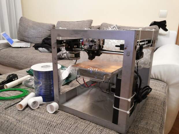
A 3D printer producing the main body of a button-dispensing machine.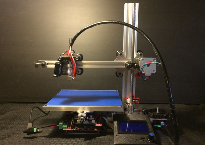 Jeremy S. Cook
My printer came with a sample model on the included SD card, which is a good place to start if you want to see if your printer actually works. Personally, I had no interest in a small plastic cat, and instead turned to Thingiverse to find a small enclosure for an electronics project I was working on.
These files generally come in a stereolithography (STL) format, and you’ll need to load them into a slicing program like Cura to generate the actual G-code file that controls your printer.
Obtaining files in an STL format means you can modify the models you download to fit your printer and adjust how you want things printed. For example, you may want certain wall thicknesses, print speeds, or infill properties (how solid the inside of your print will be) that affect the final product.
There are a wide variety of printable items available on Thingiverse and many other download locations, but in my opinion, the real magic of 3D printing occurs when you design custom parts.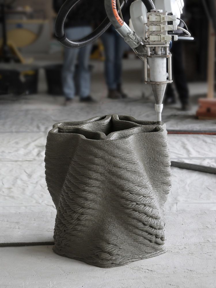 Personally, I design most of my projects in Autodesk Fusion 360, but programs such as Tinker CAD and OpenSCAD are also popular modeling options.
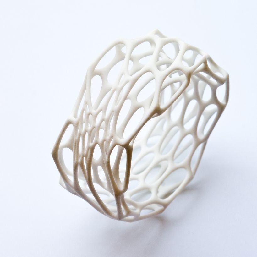
After making projects for years with more traditional tools, it’s amazing to be able to simply press a button and have my printer generate a part. In my case, these have usually been brackets and small spacers for robotics and other projects, but more decorative items are also quite popular and can be finished and painted to make them really stand out.
How to Set up a 3D Printer for the First Time
Revolutionized is reader-supported. When you buy through links on our site, we may earn an affiliate commision. Learn more here.
Whether you just brought home your first 3D printer or received one as a long-awaited birthday gift, you’re probably wondering how to set it up. If this is your first time playing with a 3D printer, don’t worry — we’ve got you covered. Here are some tips and tricks to help you learn how to set up a 3D printer the first time.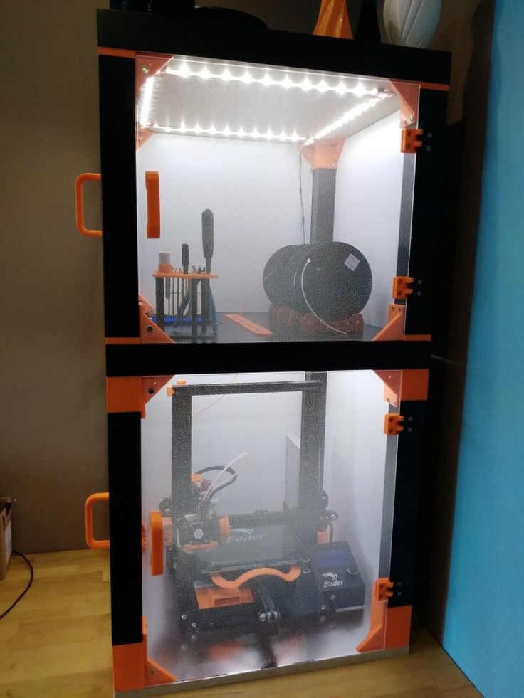 Plus, we’ve included a few ideas of printing projects to try out once you get everything up and running.
What Type of Kit Do You Have?
First, what type of 3D printing kit do you have? Most kits come in one of three styles — pre-assembled, partially assembled or DIY. The type of printing kit you have will determine how much work it will take to set it up. Pre-assembled kits are ready to use right out of the box. While they might need a little bit of setup before you can start printing — which we’ll talk about more in a minute — they’re generally plug-and-play ready.
Partially assembled kits are usually split right down the middle and packaged to save space. You’ll typically need to bolt them together and make a few electrical connections before your new printer is ready to use.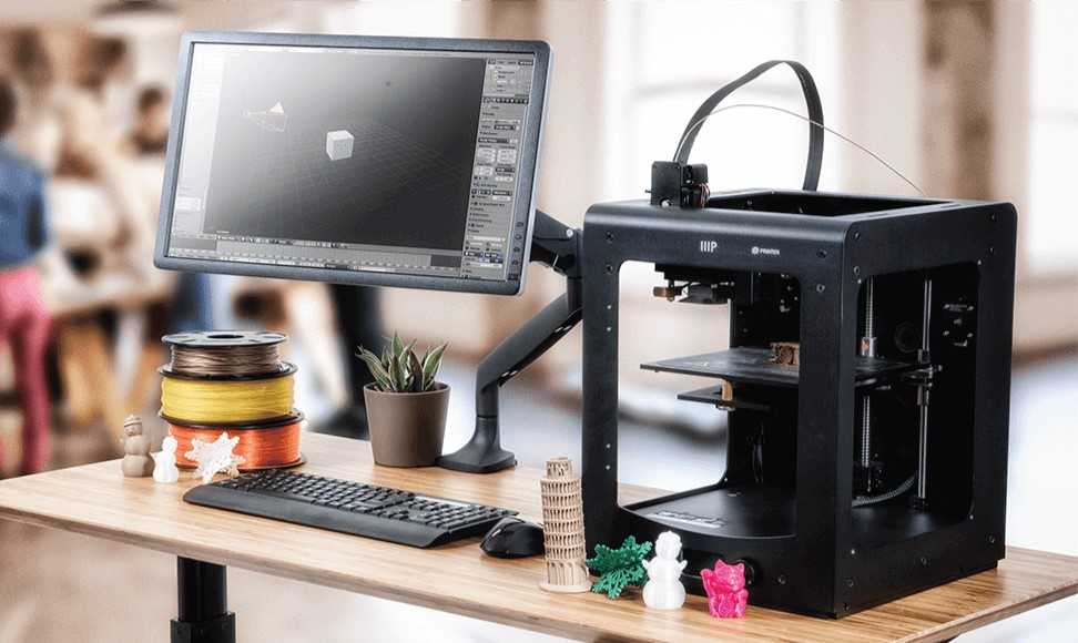 DIY kits take quite a bit more assembly and will likely take you longer. Once you know what type of kit you have, move on to the next step of how to set up a 3D printer.
Follow the Instructions
This step might seem like common sense, but it bears repeating: Make sure you read the assembly and setup instructions. Take the time to read through them thoroughly before you start making connections or putting things together. Don’t try to set up anything or start playing with the printer until you have all the information possible. Right out of the box, it’s essential to read the instructions. Once you have everything assembled and calibrated, you won’t have to do a lot of tweaking.
This advice is especially crucial if you’ve got a partially assembled or DIY kit. Part of knowing how to set up a 3D printer is making sure to connect all your wires, balance the device and secure it before you try to print anything.
Don’t Assume It’s Already Calibrated
If you have a fully or partially assembled 3D printer, you might feel tempted to start printing as soon as you hook it up to your computer. However, you might end up wasting a lot of filament by assuming your printer is already fully calibrated. Even if it’s supposed to come calibrated and ready to use, things can get knocked out of alignment during shipping. If you’re too rough with it when you take it out of the box things can also get misaligned.
Luckily, calibration instructions should be a section in your instruction manual. Go over them and make sure to properly calibrate everything before you click that print button. Mild calibration errors might not cause problems, but significant errors could damage your equipment. Don’t print with an uncalibrated machine.
Make Sure Everything Is Square and Level
For this step, you’ll want to break out a level and T-square or other similar tools. If the frame isn’t square and the printing bed isn’t level, everything will end up crooked and lopsided. Unlevel machines could also lead to the hot print head, the thing that melts the plastic filament, melting into the print bed. Any way you look at it, printing without a square and level printer will be a giant mess.
You don’t need a lot of extra tools to ensure everything is squared away, but if the print bed isn’t level, there aren’t a lot of ways to fix it, short of ordering a new printing bed and starting from scratch. Some printers will come with an option to adjust the level of the print bed, so again — check your instructions.
If the printer does not have an auto-leveling feature, you’ll need to adjust the screws found at each corner of the print area. The goal is to make the surface and print area a uniform distance from the extruder. Your printing manual should have more specifics about the optimal measurement between the printing surface and extruder.
It may also include tips on how to get the right distance. One possibility suggested by at least one printer manufacturer is slipping a piece of paper between the printing surface and extruder. Encountering slight resistance when sliding it is a good sign.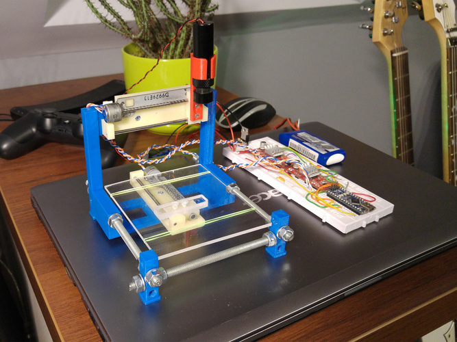 However, since printer models vary, always prioritize what the printer’s manufacturer suggests over more generalized guidance.
Lubricate Everything Sufficiently
3D printers have so many moving parts that adequate lubrication is essential for regular operation.
A good rule of thumb is that a component needs lubrication if it moves against another surface. However, the part receiving lubrication determines the best product to use on it.
One of the parts requiring lubrication is the threaded rod and nut along the Z-axis that change the printer nozzle’s height. The X and Y-axis guiderails along the print head and print bed also need lubrication. Besides promoting a hassle-free printing process, proper lubrication helps prevent the premature breakdown of parts.
A lubricant’s suitability for a 3D printer depends on how well it protects against the adverse effects of materials rubbing together and whether it helps the printer components move smoothly during operation. Because it’s so popular and widely available, some people wonder if they can use WD-40 as a lubricant. However, it’s not a suitable option, regardless of the brand of printer you have. Ongoing and excessive use of the product could even damage the printer.
Check your owner’s manual or setup instructions to find out what kind of lubricant you should be using, as well as your maintenance schedule. It’s one of those questions that if you ask 10 different people, you’ll get 10 different answers. Therefore, it’s always best to refer to your owner’s manual.
Before you start printing, slide the print head along the axles and manipulate the other moving parts to ensure that everything moves smoothly. There shouldn’t be any grinding. You’ll notice if there’s a problem, and it’s always better to find out before you’ve started printing.
Set the Desired Print Speed
One of the main advantages of 3D printing is that it is much faster than many other production methods. So, many people understandably wonder how the print speed affects the print quality.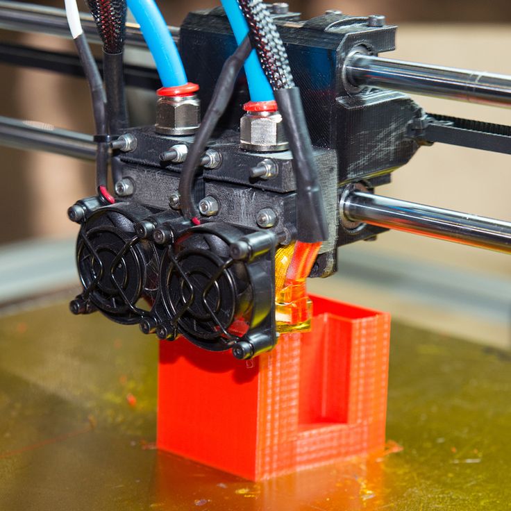 Generally, slower print speeds result in better-quality results. However, the specifics vary depending on the types of materials used and what the printing project involves.
As the extruder moves progressively faster, it vibrates more. That effect causes a reduction in the overall print quality. Many people find it particularly noticeable on consumer-grade printers. Manufacturers typically don’t make those with the expectation that people will be trying to print at very high speeds.
Whether a printer can handle a certain speed is not the only consideration. Limitations also exist regarding how fast the printing filament melts, impacting the maximum extruder flow speed. Different filaments have various physical and chemical properties. So, just setting the same print speed with two types of filament is not necessarily enough to get a similar outcome with each attempt.
Feed Filament Into the Extruder
The filament has a significant impact on the printing process.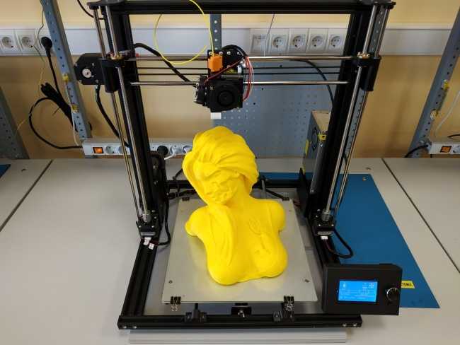 Check the instructions associated with the printer and filament before proceeding. Some people recommend making a sharp, angled cut at the end you feed into the printer so it’s easier to load. Some printer models come with a cutting tool. Filaments may also have circular ends, and people sometimes find them harder to load. Bending and twisting the end before feeding it through can help.
Push the filament through the extruder’s entrance and keep going until you feel a bit of resistance. Then, the filament has likely reached the nozzle.
Choose a Design
Setup is complete and you have everything ready to print. The next thing you need to do is choose and create a design. You can make nearly anything with a 3D printer — from a tripod for your phone to a bag hook so you can carry in all your groceries in one trip. There are plenty of options available for free online for you to choose from, or you can create designs in a CAD program.
It might be easier to ask what you can’t make with a 3D printer than to list what you can create with these devices.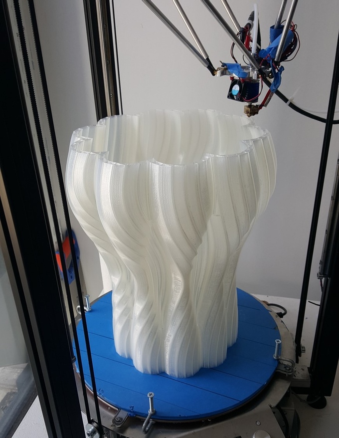 You can make everything from guitars and camera lenses to 3D printed models of anything you can scan. This could even include a working gun if you’ve got the right supplies. Even NASA uses 3D printers to send patterns for specialized tools to astronauts on the International Space Station.
Go From Learning How to Set Up a 3D Printer to Your First Project
Finally, once you’ve got everything set up and chosen your design, all that’s left to do is click print! 3D printing projects can take anywhere from a few hours to a few days to complete, so be patient. All your hard work will be worth it.
Editor’s note: This article was originally published on January 21, 2020 and was updated August 26, 2022 to provide readers with more updated information.
Revolutionized is reader-supported. When you buy through links on our site, we may earn an affiliate commision. Learn more here.
Instructions for setting up all the mechanics of a 3D printer: from belts to speeds
The quality of the printed models directly depends on the mechanics of the printer, namely on its correct settings. Any elements of the printer wear out over time, so the printer must be set up at least once every 5-6 kg of printed filament. With the help of the short instructions described in this guide, you can quickly and easily set up the mechanics of your printer: belt tension, motor current, motor steps, acceleration, jerk and speed.
Mechanics includes
3D printers of any design always contain the same things: Axes and rails along which the elements of the printer move and motors with belts that set these elements in motion. In a classic printer design, there are at least 3 motors (one for each axis), 3 rails (one for each axis) and an electronics board that controls the motors. The latter can hardly be called part of the mechanics, but since it controls the engines, it also indirectly affects the quality of the model.
Printing defects due to mechanical problems
Before changing anything in the printer, you need to decide what exactly needs to be configured. Often defects are visible visually. Our blog has an article about most printing defects, which details the reasons for their occurrence. The following is a list of defects and what element of mechanics they are associated with:
-
Layer shifting - Belts, Motor current, Guides
-
Ringing - Guides, Speed
-
Incorrect model geometry - Guides, Motor steps, belts
As you can see, all the above problems do not interfere with the printing process itself, but the result leaves much to be desired. Sometimes mechanical errors can completely stop the printer from working. Therefore, it is better not to take the situation to extremes and, if any problems arise, immediately start checking and configuring the 3D printer.
How to save settings
To fix some defects, you need to change the printer software settings. Therefore, before adjusting the mechanics, it is necessary to understand how to properly store the settings inside the printer. There are 3 ways to do this:
All settings are located in the corresponding menu of the printer
Depending on your firmware, this manual will indicate code sections for MARLIN firmware in the configuration.h file
We first enter the parameters into the printer and then store them in EEPROM - the internal memory of the microcontroller. Or paste all the necessary settings at the beginning of GCODE. To learn how to do this, read our article on working with GCODE and creating macros.
To save to EEPROM, you need to send the printer a command to change some value (which can also be inserted into the initial GCODE), and then send the M500 command (save the current settings to permanent memory). The EEPROM function must be enabled in the firmware, for this you need to remove two slashes in the line:
//#define EEPROM_SETTINGS
Whichever option you choose, you should be careful when using any commands. You will not be able to harm the printer in any way when changing the settings, but if you make a mistake, you will have to look for the cause of possible further problems for a long time.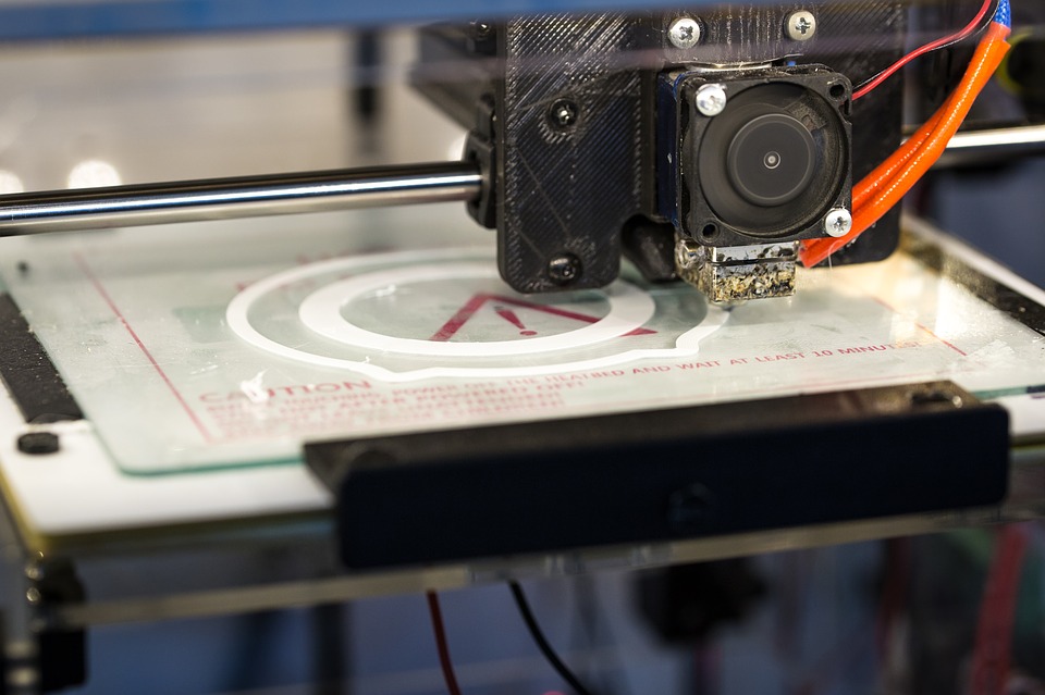
Setup instructions
Now you can start setting up the printer itself. If you decide to set several parameters at once, then it is better to use the order of adjustments as in the article, since some of the settings are related to each other and if you use the wrong order, adjusting one element of the mechanics will override the settings of another element. For example, you should not adjust the motor steps before tightening the belts, as changing the length of the belts will change the "true" steps per millimeter of the motors. Also, before setting up, you must make sure that there are no backlashes in the printer frame, tighten all belts.
Belts
The first thing to start setting up the printer is the belts. They directly affect the geometry of the model and, when pulled too much, they cause a lot of problems: displacement of layers, changes in geometry, ripples. First you need to make sure the belt is intact. To do this, look at the entire belt, especially the areas where the belts bend.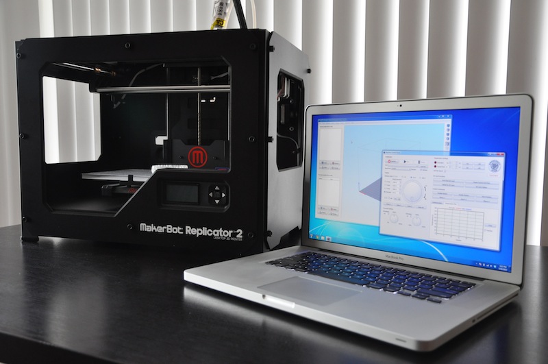 If the belt has outlived its usefulness, then you can see a section of the belt where the distance between the teeth has greatly increased and a metal wire (cord) is visible between them. This means that it's time to completely change the belt.
Broken belt with broken cords
If the belt is intact or you have already replaced it, then you can proceed to the next step. Depending on the design of your printer, you need to move the roller through which the belt passes. The tension should be such that the carriage or table moves effortlessly, but at the same time, when moving quickly, the belt should not slip the teeth on the motor gear. Adjust the tension of the belts on each axis of the printer using this method.
Tip: if your printer came with a belt tensioner in the form of a spring attached to the belt itself, remove it. Due to the flexibility of this tensioner, printing defects will occur, such as protruding corners on the model.
It is better to adjust the belt without using this tensioner.
Belt tensioner
Current motors
As we know from the school physics course, the power of the engine depends on the voltage and current strength. Since the voltage on all printer electronics is the same everywhere, the only thing that can be changed is the current on the motor. More precisely, it should be said the maximum current that the driver will supply to the motors. To change this limit, you need to climb inside the case and find the printer board. On it you will see the printer driver. We are interested in a small potentiometer on the driver itself (in the picture below it is indicated as a tuning resistor).
Potentiometer location example on driver
For adjustment, you will need a voltmeter and a small Phillips or flathead screwdriver. Before proceeding further, it is necessary to calculate the maximum current supplied to the motors. Different formulas are used for different drivers, the most popular ones will be listed in the table below:
| Driver name | Formula | Explanations |
| A4988 | Vref = Imax * 1.25 for R100 | To understand which formula to use, you need to find a resistor with the signature R100 or R050 on the driver. They are located next to the driver chip. |
| DRV8825 | Vref = Imax / 2 | |
| LV8729 | Vref = Imax / 2 | |
| TMC2208 TMC2100 TMC2130 | Vref = Imax * 1.41 | One formula for all drivers |
The value of the maximum current (Imax) depends on the motor controlled by the driver. This can be found in the engine specification or on the sticker on it. The following are the currents for the most popular motor models:
17HS4401 - current 1.7 A
17HS8401 - current 1.8 A
17HS4402 - current 1.3 A
Substituting the value into the formula, we get the Vref value for the maximum current supplied to the motor. But at this value, the engine will get very hot, so the resulting Vref value must be multiplied by 0.7. For example, for a motor with a maximum current of 1.5 A and a TMC 2208 driver:
Vref=1.5*1.41*0.7=1.48V
Now the resulting value can be used when configuring on the printer itself. To do this, disconnect the wires going to the motors, turn on the printer and place one voltmeter probe in the center of the trimmer, and the second probe to the negative terminal on the power supply (you can also use the negative terminal on the printer board and the contact on the driver, labeled as GND). You will see some value on the voltmeter screen. Turn the trimmer clockwise to decrease the Vref value and counterclockwise to increase it.
Attention: you should not specify a Vref value higher than the maximum calculated for your engine! Otherwise, the engine will soon break down!
Once you have adjusted the value on the drivers, you can turn off the power to the printer, connect the motor wires, and put the case back together. This completes the driver setup.
Motor steps
When setting up motor steps, you will need a ruler. For convenience, you can use the program Repetier-Host. The adjustment for each of the three axes occurs according to the same algorithm:
-
Set the caret to zero coordinates (Autohome or G28)
-
Move the carriage some distance
-
We measure how far the carriage has traveled
-
We calculate the correct number of steps per millimeter using the formula:
True steps per millimeter = current steps per millimeter * reported distance / distance traveled
For example, if the printer was set to 100 steps/mm, we tell the printer to move 80mm and the printer travels 87. 5mm. Then the correct steps per millimeter would be 100 * 80 / 87.5 = 91.42 steps/mm. For the convenience of measurements, you can fix a ruler on the table, and a thin object, such as a needle or pin, on the carriage. Then it will be possible to accurately measure the distance traveled. The extruder uses a partially different algorithm to measure distance:
-
Inserting plastic into the extruder
-
Cut it right at the outlet
-
We give the printer a command to stretch the plastic a certain distance (at least 100 millimeters)
-
Cutting plastic again
-
We measure the length of the resulting piece of plastic
-
We use the formula from the previous algorithm
Next, the settings data must be inserted into the firmware in the line:
#define DEFAULT_AXIS_STEPS_PER_UNIT {X,Y,Z,E0}
X,Y,Z and E0 should be replaced by the steps per millimeter for each of the axes, respectively. Otherwise, you need to insert this line into the initial GCODE:
M92 Ennn Xnnn Ynnn Znnn
Instead of nnn in each of the parameters, you must substitute the steps per millimeter for each axis. If you want to adjust the steps only for not all axes, then you can remove unnecessary parameters.
Acceleration
This parameter is responsible for the rate of change of speed. That is, how fast the printer will change its speed. This affects the nature of the movement of the hot end relative to the table. If the acceleration is too small, then the printer will print slowly, if it is too large, then the outer surface of the model will have visual defects: fading waves will be visible near each of the corners, as in the picture below.
To set up acceleration, you need to follow simple steps:
-
Cut a model of a standard test cube with a wall thickness equal to one nozzle diameter, without filling and top layers, bottom 2-3 layers;
-
Open GCODE file in notepad;
-
Find the G28 command at the very beginning and insert the line data after it:
M201 X5000 Y5000
M204 P500 T500
-
Save the changes, print the model according to the received GCODE and note at what parameters P and T it was printed;
-
Open the same GCODE file and change the P and T values on the second line, adding 500 to each;
-
Repeat steps 4-5 at least 3 times;
As a result, you will get several test cubes, some of which will show waves at the corners.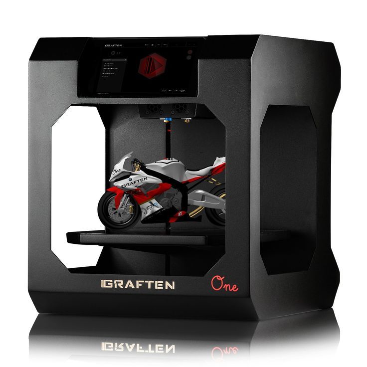 Choose the cube that is printed with the highest P and T parameters, but that no waves can be seen on it. The number in parameter P will be the desired acceleration value. To save this value, you need to find 2 lines in the firmware:
#define DEFAULT_MAX_ACCELERATION {X,Y,Z,E0}
#define DEFAULT_ACCELERATION {nnn}
Instead of X and Y, you should put an acceleration twice as high as found earlier. And instead of nnn, you need to put the acceleration value found earlier. Otherwise, you need to insert a line in the initial GCODE:
M204 Pnnn Tnnn
In the parameters P and T, you need to put the value of the found acceleration. After that, the acceleration setting can be considered complete.
Jerk
A jerk indicates the speed with which to start accelerating. It affects the model in a similar way as acceleration: it creates ripples around the corners of the model. But it also increases the protrusion of the corners if the jerk is too small.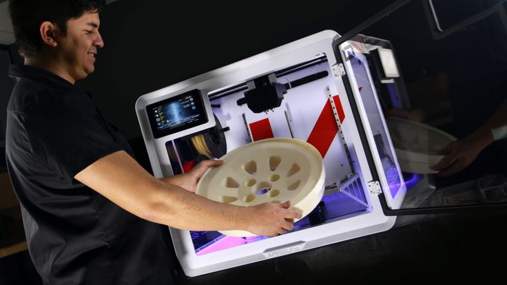 The jerk setting is also similar to the acceleration setting:
-
Cut a model of a standard test cube with a wall thickness equal to one nozzle diameter, without filling and top layers, bottom 2-3 layers.
-
Open GCODE file in notepad
-
Find the G28 command at the very beginning and insert the line data after it:
M205 X5 Y5
-
Save the changes, print the model according to the received GCODE and note at what X and Y parameters it was printed
-
Open the same GCODE file and change the X and Y values on the second line, adding 2 to each
-
Repeat steps 4-5 at least 3 times
As a result, you will get several cubes. Find a non-rippled cube printed at the highest X and Y settings. This will be the jerk value for your printer. To save them, you need to find the line in the firmware:
#define DEFAULT_XJERKnnn
#define DEFAULT_YJERKnnn
It is necessary to substitute the jerk values for the X and Y axes, respectively.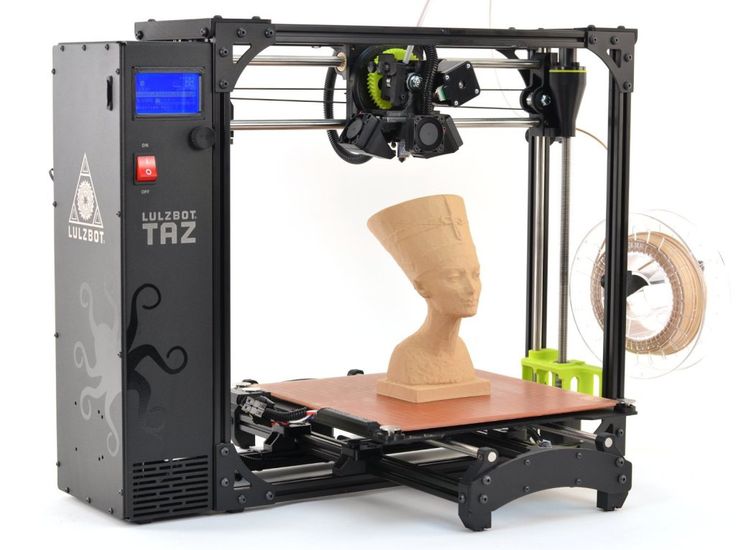 Otherwise, you need to substitute the command in the starting GCODE:
M205
Instead of nnn, you need to substitute the jerk value found earlier. This completes the jerk setting.
Speed
In fact, there are many different speed parameters, the values \u200b\u200bof which vary greatly. Let's take a look at the main ones:
This parameter is responsible for moving the nozzle without extruding plastic. The value is in the range from 80 to 120 mm/s. Limited only by the maximum speed at which the motors can rotate. Does not affect the model
This speed is important because it indirectly affects the adhesion of the model to the table. Usually lies between 15 and 30 mm/s
-Print speed of inner walls
Usually set to about 60 mm/s, it only affects the strength of the model. Depends on the maximum amount of plastic that the extruder can push through the nozzle
-Speed of printing outer walls
Usually about half the printing speed of the inner walls (30 mm / s). It affects not only the strength of the model, but also the appearance: the lower this speed, the smoother the walls will be.
The standard value is 80 mm/s, it only affects the strength of the model
Usually set from 20 to 40 mm/s, the quality of the upper layer of the model depends on it: the lower the value, the smoother the cover.
All of the above parameters are selected experimentally. Usually there is a simple rule: higher speed - lower quality. Therefore, do not try to find the ideal value for all situations. It is better to find values for fast printing, quality printing, and an average that will be used for most models.
Check settings
The last step in setting any of the above parameters will be to check the result. If you have written parameters in firmware or saved them in EEPROM, you can use the M503 command. It will display all printer settings on the computer. To test the settings in practice, you can print several test models:
Classic Benchy
Simple calibration cube
Calibration cat
On each of the above models, defects will be clearly visible, if they still remain after the mechanics are adjusted.
Optimal Cura settings for PLA 3D printing
3DPrintStory 3D printing process Optimal Cura settings for 3D printing with PLA plastic
Through trial and error, you can gradually fine-tune your Cura settings for 3D printing with PLA (as well as many other 3D printing materials). The article below provides recommendations from personal experience that may be helpful if you are using PLA plastic on your 3D printer and Cura to slice and prepare your 3D print modes.
In addition to explaining preferred temperature settings, advanced support and infill settings are detailed, along with many other factors that affect 3D printing without defects or issues.
*** The following settings are for Cura and tested on Lulzbot TAZ 3D printers with an E3D host.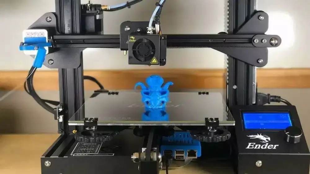 We have successfully used these settings on our TAZ3 and TAZ5 printers as well as the HATCHBOX 3.0mm PLA. Simplify 3D uses very similar profiles. Environmental conditions and material manufacturer can also greatly affect these settings
3D print quality settings
The height of the 3D print layer is very dependent on the nozzle size of your 3D printer, as well as the quality you want to achieve. A 3D printer with a 0.6mm nozzle can achieve layer thicknesses of up to 0.4mm, and a part with a layer height of 0.1mm will take twice as long to produce as one with a 0.2mm nozzle, so these factors are important to consider.
Our default 3D print quality setting is 0.25mm layer height. Then we fine-tune the retract settings for the PLA. The resulting profile for Cura will be:
- Minimum Travel: 1.5mm
- Enable Combing: All
- Minimal Extrusion Before Retracting: 0.005mm
- Z Hop When Retracting: .1mm
trying to eliminate gaps. This will help prevent "burrs" from appearing on the sides of the 3D model. "Z Hop" is set to 0.1mm when retracted, so thin sections of 3D models are less likely to be damaged.
When we click on the "Advanced Settings" tab in Cura, we look at the "Retraction" and "Quality" sections. We set the retraction speed to 10 mm/s and the distance to 1.5 mm. In the "Quality" menu in the "Advanced section" we do not increase the initial layer thickness, but increase the initial line width to 115%. We have found that this helps improve adhesion to the table without compromising the quality of the 3D print.
The figures below show examples of 3D printing. From left to right, 100 micron layer height (high quality), 250 micron layer height (standard quality), and 380 micron layer height (draft quality).
Infill settings
To get a clean PLA print, we always try to include at least 4 bottom/top layers (i.e. you have to multiply the layer height by at least 4). It can increase depending on how flat the object is, how high the fill density is set, and how thick your layer is. A long rectangular piece with a layer height of 0.1mm will require more than 10% infill and at least 7 bottom/top layers to avoid pitting. The print below had just such a problem: too little infill and too few bottom/top layers, spoiling the 3D print result.
The preferred infill density percentage is unique to your particular 3D model, as are the quality settings. Infill overlap settings are something to focus on to improve the surface quality of a 3D model.
This 3D model had 10% infill and 3 bottom/top layers at a layer height of 0.25mm which was not enough for a smooth top surface.
This 3D model had 20% infill and 5 bottom/top layers at a layer height of 0.25mm, which was enough for a beautiful outer surface.
Infill Overlap
Infill Overlap refers to the percentage of infill overlap on the shells. When the number of shells is low and the percentage of infill overlap is set above 12%, we notice "veining" on the surface of finished 3D models, especially on large translucent PLA parts.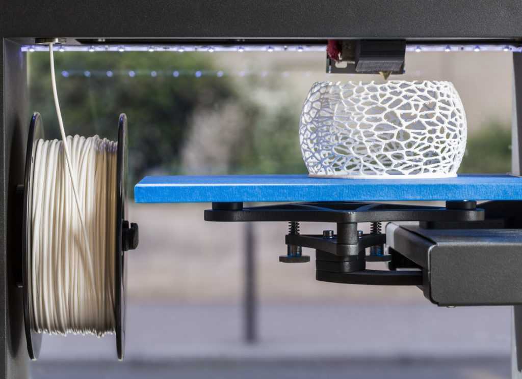 We prefer almost all of our PLA models to have an 8% overlap. The photo below shows an example of two shells with a 15% overlap of translucent blue PLA. While the effect looks pretty cool, we needed to reduce the fill overlap to get this veining defect to disappear.
Speed and temperature
As we warned above, these PLA settings work well with E3D enabled Lulzbot TAZ printers. These temperatures (and speeds) may vary depending on the 3D printer and how long it has been used.
Our nozzle operates at a comfortable (but slightly higher than average) temperature of 205-210°C for PLA. We usually preheat the table to 60°C, but since we added a thicker 1/4 inch glass, we increased it to 65°C. This thicker glass makes the table process easier and also prevents cracks and chips. We've used PLA on tables that don't have a heating option, but it's definitely better to have a heated table. The glass stage heated to 65° helps prevent warping and prevents parts from being torn off during the 3D printing process.
We run our printers a little slower to ensure the best surface quality. We usually set our average speed to 60mm/s, with slower settings for the outer and top/bottom layers. In advanced mode we have the following speed settings:
- Travel Speed: 150 mm/s
- Bottom Layer Speed: 25 mm/s
- Infill Speed: 60 mm/s
- Top/Bottom Speed: 40 mm/s
- Outer Shell Speed: 40 mm/s
- Inner Shell Speed: 60mm/s
Support Material Settings
We found the support settings to be one of the hardest things to change. Each material requires a different infill percentage and angle. Each one also requires a unique distance from the 3D model for easy removal.
Anyone who has been typing long enough probably doesn't like working with caliper settings. Our recommendations for support material settings are as follows:
- Structure Type: Lines
- Overhang Angle for Support: 50°
- Fill Amount: 15%
- Distance X/Y: 0.
 8mm settings
 - Distance Z: 0.16mm
support, you will also find a type of base to grip with the table. While "brim" settings are not usually needed for PLA parts, large 3D models can warp and narrow parts have a hard time sticking to the table without tipping over. In our PLA settings, this option is usually disabled by default, and we enable it manually for such special cases.
The problem with base coats, especially on PLA, is that they are difficult to remove. We've had parts where the edge is much harder to remove than the base backing material. This forced us to switch to the narrower "skirt" version instead of "brim".
With "None" selected as the first layer type, click "…" to see more options. Then we change the number of lines to 10-15, the initial distance to 0.01mm and the minimum length to 250mm. This allows the first layer to form only on the outside of the 3D model. Although the outer side will still require additional processing, this saves a lot of time removing margins from the inner thin parts of the 3D model.