3D printing letterpress plates
Hi-Tech meets Old-Tech: 3D Printing for Letterpress
Graphic Design
Posted by cmedley235 on
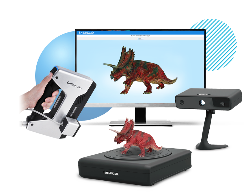
I conducted a materials research study determining what 3D printing materials will best serve in relief printing processes applicable to letterpress and printmaking. With the help of a Marywood University grant, local 3D expert Cole Hastings and the company Printed Solid, I bought a 3D printer and a variety of filaments to play with—ranging from polyester to metal powders to plant-based materials.
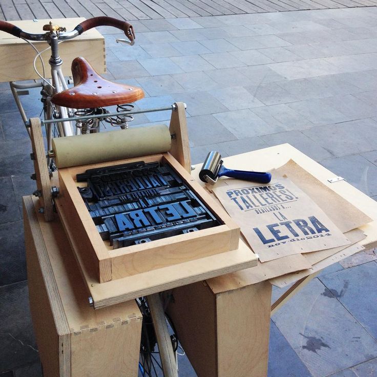
1960s Kelsey press locked up with 3D type
So why would I want to make 3D printed letters? I have a large collection of wood type at my letterpress shop, The Workshop, but some fonts are missing letters, or the letters are damaged or I don’t have enough of a common letter like an “E”. These are some of my short- and long-range goals:
- Fabricate missing letters for wood type fonts
- Create new letterpress fonts that replaces traditional wood type
- Create an alternative relief plate making process to polymer, linocut, and woodcut
Some of the qualities I’m looking for in the filaments are:
- How does it hold up to the pressure of a printing press?
- Does it have similar surface properties to wood?
- How does it hold fine detail?
- Can you sand, carve or using fillers?
Not to bore you with too much detail but the testing process generally went like this:
- Created the letter in Illustrator, saved out as SVG and used the free 3D modeling program Tinkercad to create a STL 3D model.
- The letter A was printed on the Lutzbot Mini 3D printer using these 9 filaments: ColorFabb NGEN, _HT, PLA/PHA, Bronzefill, Corkfill, Woodfill; Proto-Pasta Carbon Fiber; and 3-D Fuel Natural Entwined Hemp
- All letters had to be sanded, most of the time an emery board sufficed.
- Models had to be made slightly higher than the type high .918 to allow for sanding. 3D modeling is measured in mm so it’s interesting, to say the least, having to convert from points, picas and inches into the metric system
- Then printed on two different printing presses: Kelsey and Showcard.
[wpvideo n0ku1zvJ]
So after printing and testing out 9 different filaments and a much fussing around (3D printing takes a lot of patience), the best filament I found that gave me the closest feel to wood type is—drum roll—ColorFabb Bronzefill. This filament has bronze powder in it, is more durable with a heavier weight than the plastic filaments and is easy to sand and polish.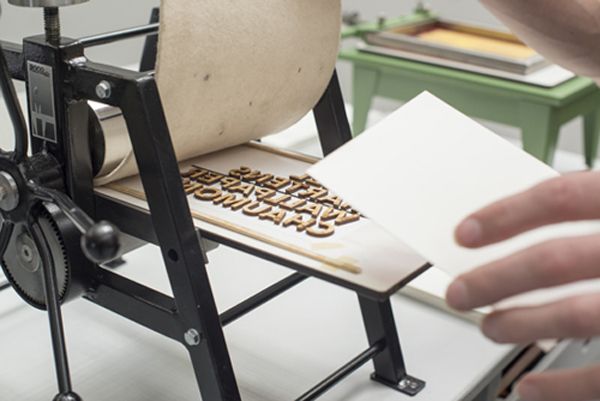 It even sparkles in the light because of the bronze powder. It does have a higher cost than the other filaments and takes a bit longer to print (45 minutes per 2-inch letter). There were others that were ok with my next favorite being the hemp filament. My least favorites are the polyester and PLAs. There are many more filaments out there and they are improving, so this will be an ongoing process until I find the perfect one.
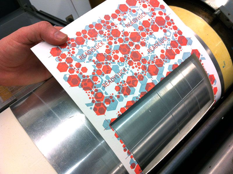
Some of the test prints:
ColorFabb Bronzefill is the winner so far: sanded with emery board.
PLA/Carbon/Hemp
First prints that were least successful–HT printed upside down and one painted with shellac
3D print your own custom letterpress plates – Mostly Gold Everything
I’ll start with a preface: I am certain I am not the first person to think 3D print custom letterpress plates, but I had a hard time finding a full tutorial on the process top to bottom. This tutorial is not for beginners of any kind. You need to know design and 3D print basics, although I’ll provide resources for more on those topics. Here’s a breakdown of the equipment and software skills necessary so you don’t feel drawn in only to realize there is hundreds of dollars of equipment you still need to buy. I already had a lot of this on hand from other projects, so it didn’t feel so steep. I’ve estimated the costs but some depend on what you buy or change frequently on Amazon, but it should give you a good idea.
Also before we get started, check out these resources if you need to know the basics of lettering with Procreate on the iPad Pro, vectorising your Procreate art with Adobe Illustrator, printing with the L Letterpress or using a 3D printer. From this point on, I am assuming you know all of these things! 
3D-ifying your art file with TinkerCad
I have to say again, I’m assuming you already know the basics here. I’m not remotely qualified to tell people how to use a 3D printer, I’m learning! But here are the steps you need to know to successfully print a letterpress plate.
- Use “Save As” to save your outlined .
 SVG in Illustrator
 - For some reason, exporting as an .SVG doesn’t work. Don’t forget, like I did, to flip the image. If you don’t, your lettering or art will be backward. Don’t say I didn’t warn you.
- Import the .SVG of your design file into TinkerCad
- This can be anything! I used something I lettered in Procreate, but you can use honestly anything your little heart desires.
- Change the height of the art file to 1.8 mm
- I came to this number by using electronic calipers to measure the standard plates that came with my L Letterpress.
- Scale the file to your desired sized
- Everything in 3D printing is in millimeters, which I just am too American for, so I am on Google running conversions to inches all the time. Just like in Illustrator, holding down the “shift” key will maintain your aspect ratio. This one will end up being about 3.5 inches square.
- Create the base of your plate.
- When you’re starting out, it can just be a rectangle plate that goes behind the art file. (I’ve moved on to creating outlines of my art to use as the base, but trust me this is easiest for now and you can always cut down the base with scissors after the fact.) Use the square tool in TinkerCad and change the height to .65 mm, then scale to be just slightly larger than your art file. For this file I used “holes” to cut off excess bits of plate, but it’s not necessary.
- Group your art file with the plate base
7. Export your file as a .STL
Preparing your file to print
- Open Cura, start a new project and open your .STL file
- Make sure all your settings are correct under “printer settings.” When I swapped out my .4mm extruder for a .2mm, I had to hop in and make that change in Cura as well.
- On right hand side, change layer height to .06.
- Move infill over to 100%
- This isn’t common when making a 3D file but you need a solid fill for these plates.
- This isn’t common when making a 3D file but you need a solid fill for these plates.
- In the “custom” panel, under “Shell” click “Enable Ironing” and then “Iron only highest layer” when that checkbox appears. I also changed the ironing pattern to “concentric” and ironing speed to 60 mm/s.
- Press “Prepare” in lower right hand corner.
- Change from “Solid View” to “Layer View”
- Press play to see how your plate will be printed.
- This is where you’ll see any potential errors in your settings. If your lines are breaking, lower the print speed and prepare your file again until your details render properly. Obviously this will result in slower print times.
- Press “Save to File” and save as a .gcode
- Send to 3D printer
- For the Ender 3, I put the file on a micro SD and plug it in to my printer. Make sure you’ve labeled your file appropriately, because you’ll need to pick it out from the screen on your printer.
- Here’s the finished product, along with some extras I made using a graphics pack I bought on Creative Market.
You are now ready to press. I learned a lot of what I needed to know out the gate from Boxcar Press. They did a great job breaking down the pros and cons of the L Letterpress and best practices to get great results with a somewhat simple too. They did such a great job, I’m not going to rehash it, just read this piece first for tips on using the L Letterpress. For this project, I arranged multiple plates to go together. This sloppy photo gives the idea.
Cleanup
The Boxcar Press post gets into that, but as you may have noticed, I ran into some trouble on this step. I full stop ruined my first L Letterpress by cleaning it that lavender brush cleaner. It ate the acrylic. I had to buy a new one. It wasn’t my finest hour. You might remember I told you to buy two cleaning products, here’s the breakdown of when and where to use them.
Baby/Mineral Oil
First of all, I wish I knew these were basically the same thing. I already had mineral oil. I’m an idiot. It’s fine. I’m fine. Anyway, this is what you need to use to clean the acrylic sheet you rolled your ink out on and any ink that smudged onto your L Letterpress. You’ll be using this as you work so keep it handy along with a stack of rags or paper towels for wiping errant ink of your plate, hands, etc.
Turpentine/Lavender brush cleaner
This is the hardcore stuff. You’ll need it to clean off the brayer and probably the 3D printed plate itself. I’ve used a toothbrush to get into the nooks and crannies but you still might end up needing to press on scrap paper to fully get the ink off. If you’re never going to blind emboss, it’s not that huge of a deal, but if you want a clean-ink free print in the future, you’ll need a little extra elbow grease.
In Conclusion
This was kind of a lot of work, right? But if you’re savvy with this stuff anyway, the process of creating print files gets very quick and I love the immediate gratification here. If I were putting together an invitation suite for someone, I would 100% get polycarbonate plates made from Boxcar Press, but for one-off cards of my own lettering, this is the route for me.
Here’s a look at the finished product. I had planned to do a two-plate press and quickly realized it was just way too much work, so the suckers who buy me baby shower gifts get just one color. Sorry.
Like this:
Like Loading...
3D printing mold making
Desktop 3D printing molding allows engineers and designers to get more functionality out of a 3D printer beyond prototyping. Molding opens up a world of production materials and provides the opportunity to produce small batches and sample test molds before using expensive
tools.
This booklet covers the following three mold making strategies: injection molding, high temperature molding and injection molded elastomers. Typically, molds are made from Formlabs clear resin, which is preferred for its transparency, although any standard resin can be used, and high temperature resin is ideal for processes with high temperature requirements.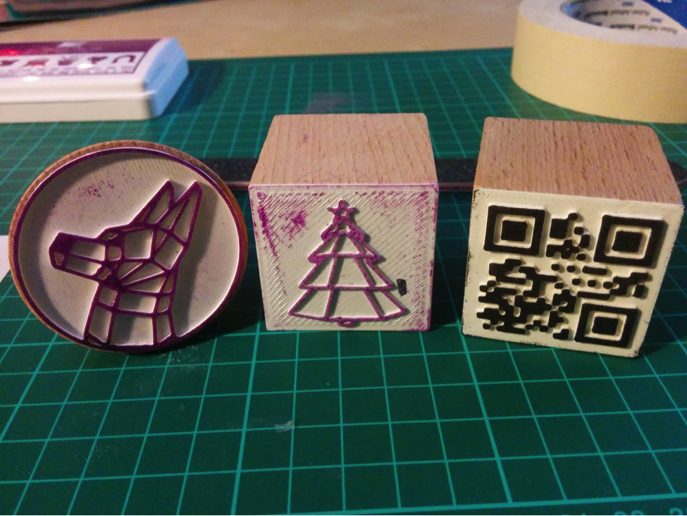 It should be noted that these processes are best suited for stereolithographic 3D printing (SLA) because the printed parts are isotropic and waterproof.
Prototyping and small-scale production with 3D printing tools
| Process | Equipment | Run time | Material cost (for example: 300 ml/cm3) |
| Do-it-yourself mold making and parts making | Mold 2 and injection molding machine | 5 to 24 hours (form print time) | Approximately $50 for High Temperature Resin |
| Outsourced SLA Form | injection molding machine | 3-5 days | Approximately $700 for back office printing on industrial SLAs |
| Outsourced metal mold | injection molding machine | 1-2 weeks | Approximately US$6,400 for office desk, aluminum finish |
| Outsourced mold Creation and production | no - full outsourcing | 1-3 weeks | $4,000 to $15,000 depending on volume and materials |
Silicone molding and some desktop molds are available using Formlabs Standard Resins High Temp, which has the highest HDT at 0.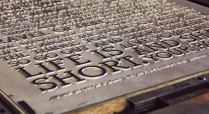 45 MPa for any 3D printed materials currently on the market and allows print parts that can be used for high temperature forming such as thermoforming and injection molding of materials with higher melt temperatures
Injection molding
High-resolution SLA 3D printing on the Form 2 can be used to quickly prototype inexpensive injection molds that can be used to make real parts from a wide variety of
thermoplastic materials. Injection molds can be used to test mold designs prior to metal tooling or to produce low-volume parts
3D Printed Injection Molding covers injection molding using Formlabs clear resin printed molds. Following the release of Formlabs High Temperature Resin, designed to achieve higher heat resistance and stiffness, the booklet has been updated to describe the benefits of High Temperature Resin plates that are less likely to break due to thermal shock or temperature-related deformation
USB Device Enclosure Mold, 3D Printed on Form 2 High Temperature Resin
This mold contains a core, a cavity, and two "gates" leading to the two halves of the enclosure.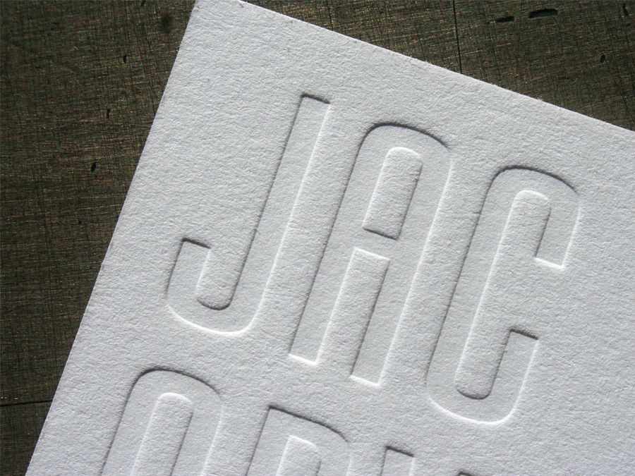 High temperature resin molds can be used to mold a wide range of thermoplastics without thermal stress or temperature-related deformation
Formlabs High Temperature Resin can be used to injection mold a wide range of plastics.
3D printed mold tools reproduce the exact quality of the SLA print finish on the Form 2. Forms can be printed at 100 microns for faster prototyping or the recommended 50 microns for fine detail and smoothness
electronics molded in HDPE with a High Temp tool.
This shape of the USB case has been adjusted over three iterations to remove cavities, entrapped air, and partial shrinkage. Total cost of materials for prototyping this high temperature resin mold tool: $25
Thermoforms
Form 2 3D printed thermoformed dies are a fast and efficient way to create high quality vacuum formed parts for low volume production. Printed thermoformed dies can be used to make packaging prototypes, clean orthodontic retainers, and food-safe molds for chocolate confectionery.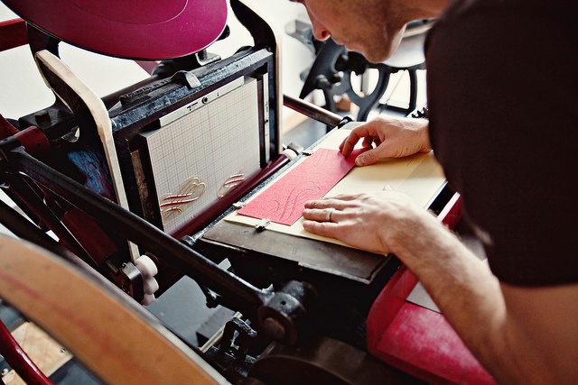
Thermoforming dies experience less pressure than injection molds, but still reach high surface temperatures.
High temperature polymer resists deformation and surface degradation from the combined heat and pressure of thermoforming for most plastics. Standard resins may also be suitable for thermoforming with some low temperature plastics such as vinyl.
APPLICATION EXAMPLE
Formech thermoformed prototype packaging.
Thermoforming a thin sheet of polycarbonate over a high temperature polymer matrix produces a transparent detail by matching the geometry and detail of the matrix. Thermoformed packaging can be easily prototyped and incorporated into the design process along with 3D printed product prototypes, and all this is achievable on the Form 2. The printed matrix was used without additional processing and the need for UV curing. Texture is recommended in thermoforming design to prevent air trapping under the sheet - layer lines on the printed thermoforming die can be helpful in this regard.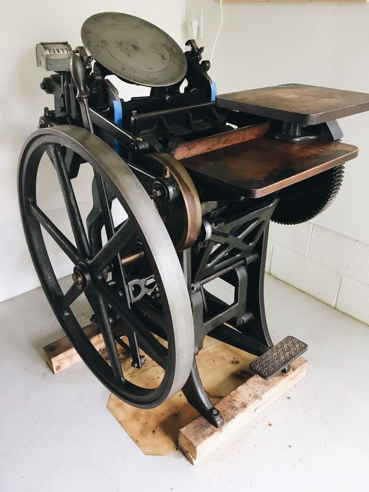
TEMPERATURE CONTROL
High Temperature Polymer Cycle Thermoforming
The surface temperature of the die reaches 130°C. The high temperature resin is highly resistant to deflection, whereas with standard resins you must allow the print matrix to cool between cycles, otherwise warping and degradation may occur.
If temperature rise becomes a limiting factor in molding efficiency, cooling channels are an effective way to remove heat from the print. When used in conjunction with an automated thermoforming machine, the water-cooled die can produce more parts with shorter cycle times.
Conformal water channels visible in the thermoforming high temperature die.
Thermoforming die surface temperature
Conformal cooling channels are easy to implement when designing for SLA 3D printing and print successfully without any internal supports to interfere with flow. After printing, the channels are flushed with uncured resin using isopropyl alcohol. The mold is connected to a pump and a source of cold water.
Integrated water cooling as a strategy can also be applied to standard and rigid polymer parts to reduce heat dissipation when used in higher temperature environments.
Elastomer casting
Precision molds for most flexible elastomers such as silicone and urethane rubber can be printed on the Form 2 using standard resin. The transparency of Clear Resin allows the material to be observed during the pouring or injection process. Flexible materials can be easily removed from rigid SLA printing plates, and applications from model production to functional molding can be obtained. Silicone molding can also be used to quickly replicate master prints, greatly reducing production time when multiple rigid parts and objects are needed.
APPLICATION EXAMPLE
Forms printed on Form 2 are used to create composite parts with advanced built-in features. Assembly subcomponents such as electronic, metal and SLA printed elements can be embedded and sealed in soft surface molds.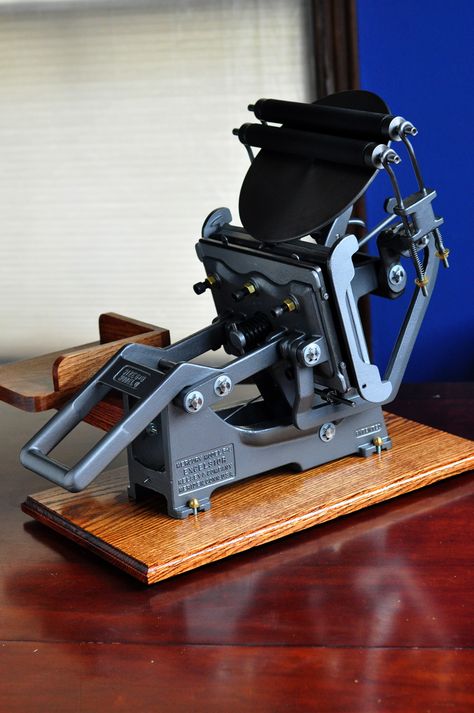
RightHand Robotics used the Form 2 to create the production blocks of their robotic gripper using urethane molding. The forms were printed in clear resin, with black resin inserts forming the internal structure.
The Form 2 printer allowed RightHand Robotics to move from prototypes to small-scale production without the need for expensive tooling. The rapid transition from original printed prototypes to production materials that have longer flex cycle life was done with 3D printed plates on the same Form 2 hardware they used for initial prototyping.
The first layer applied from RightHand Robotics' multi-stage process includes urethane compounds that can withstand multiple flex cycles while still providing the high elasticity needed to securely return the gripper to its open state.
The outer layer provides improved tactile grip and control, as well as sealing the sensor electronics with softer, lower durometer rubber.
SLA 3D printed parts can also be encapsulated inside molds to provide a rigid structure for flexible materials. The overlay can be mechanically bonded to the insert by adding holes, recesses, and columns to the printed parts, which enhances assembly and reduces the need for chemical adhesive.
Conclusion
Form 2 molding is a powerful strategy for the production of parts in small batches, as well as production from commonly used plastic and elastomer materials. 3D printing tools allow engineers and designers to easily prototype parts that look and function exactly like the final product, with geometries and material configurations that are quite complex, using 3D printing, such as in the case of encapsulated electronics and thin packaging. For high temperature forming, high temperature polymer offers superior thermal properties at a lower cost and with shorter lead times than process outsourcing
Injection molding from 3D printed molds
Study of low-volume production of small plastic parts
SUMMARY on a Form 2 printer and injection using a Galcom Model-B100 injection molding machine.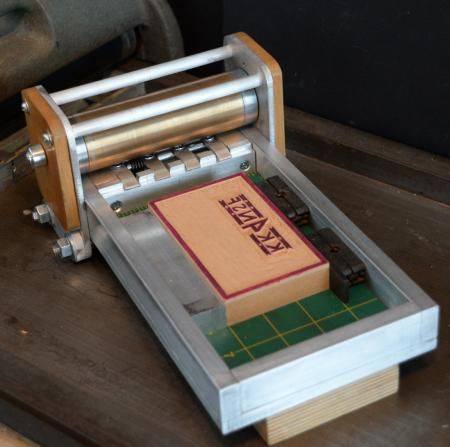 Two transparent resin molds were tested: one large butterfly mold and one mold with four small butterflies in one block. A third mold for the USB stick case was tested in high temperature polymer. These molds were 3D printed by Formlabs and the castings were made by Galomb Inc and Formlabs in a variety of materials.
Formlabs and Galomb, Inc.
LOW-VOLUME 3D PRINTED PARTS PRODUCTION
Most of the plastic products in the world today are made by injection molding. Using inexpensive desktop 3D printers and injection molding machines, molds can be created to produce small functional parts from manufacturing plastics.
For low volume production (approximately 10-100 parts), 3D printed molds save time and money. They also allow for a more flexible approach to manufacturing, giving engineers and designers the ability to easily modify molds and continue iterating their designs at low time and cost.
The Form 2 Stereolithographic 3D Printer (SLA) produces completely solid, smooth parts that can withstand the temperature and pressure of desktop injection molding.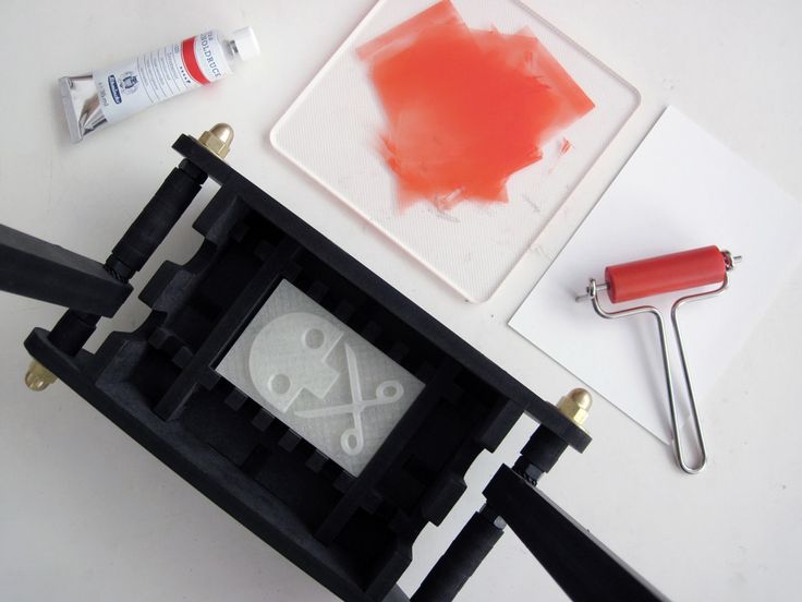 3D prints produced using SLA are chemically bonded so that they are completely dense and isotropic, producing functional shapes with a quality not possible with FDM.
Formlabs is partnering with Galomb Inc., a manufacturer of low cost injection molding machines, to test and demonstrate the viability of SLA injection mold printing.
Fig. 2 : 3D printed molds in aluminum frames.
METHOD
Both clear and high temperature resins can be used to print small functional forms, with high temperature resins offering compatibility with a wider temperature range of
thermoplastic melts. Formlabs Clear Resin was chosen for its strength, high detail and smooth surface Clear Resin is preferred for its transparency as you can easily see when forms are being filled, but any of the standard Formlabs Resins (clear, white, black and grey) can also be used as they have similar mechanical properties. The plates were printed with a layer height of 100 µm and took approximately 5 hours per plate. Depending on the geometry, multiple shapes can be printed at once on the build platform to improve printing efficiency.
Fig. 3 : Printing setup in PreForm with cavities up.
Two forms were printed from transparent resin. Parts and subsequent molds were designed to match Galomb machine vise sizes, 1 in3 injection cylinder capacity, and Form 2 build volume. supports were polished.
The parts were then cured for one hour under a 405 nm UV lamp to achieve full mechanical strength and rigidity. For a better understanding of the impact of post-curing on parts, see the Formlabs UV post-curing booklet.
Fig. 4 : 3D printed molds in aluminum frames and die-cast parts.
The first was a large Formlabs butterfly logo and the second was four small Formlabs butterfly logos. Both molds had a cavity, narrow inlets, and sprue at the point of injection and were designed in Solidworks. The molds were inserted into aluminum frames to provide protection from the downward pressure and heating of the injection nozzle. Aluminum frames can also prevent the shape from deforming after repeated use. The frames shown in figures 2 and 4 were custom made by Whittaker Engineering in Scotland, but standard aluminum frames are readily available on request from injection molding machine manufacturers.
Plastic pellets can be purchased online or from suppliers such as IASCO-TESCO. To create different colors, the molten plastic was pre-mixed with powdered dyes prior to injection.
Using a Model-B100 benchtop injection molding machine, Galomb tested printing plates with 25 shots of LDPE. LDPE melts at approximately 325°F (163°C) and was chosen for its low melting point. Of note, Formlabs Clear Resin has an HDT at 0.45 MPa 73.1 ºC after post-cure (see Material Data Sheet). HDT is a measure of the thermal properties of a material, but does not rule it out for use, although LDPE has a higher melt temperature. Whether your 3D printed mold will withstand the injection molding process depends on the melt temperature of the injection material, part geometry, and cooling and cycle times.
RESULTS FOR CLEAR POLYMER
After 25 injections of LDPE, there was no noticeable deterioration in the surface of the molds (chips, cracks or scratches). LDPE is not prone to sticking to polymer molds when tested, but other plastics may require the use of a mold remover to assist in part removal. Adhesion of the part to the mold can cause mold wear during ejection. Release agent is widely available, and silicone release agent is compatible with Formlabs standard and high temperature resins.
The cycle time for each injection was approximately three minutes. This process was accelerated by using compressed air to cool the mold. Cyclic injection into forms printed on the Form 2 causes the form to heat up. To counteract this, the cooling time between open mold cycles must be increased. While the mold cannot deform, too much residual heat will reduce molding success if the mold is opened too early. Galomb also improved molding success by etching shallow (0. 05 mm deep) vent holes (not shown) leading from cavity edge to mold edge so that air does not enter the cavity during injection.
Some of the injections showed a leak in the parting line due to deformation of the polymer mold during the cooling phase after several injections. Increasing the clamping force in the vise can help mitigate leakage, as can polishing the parting plane of the mold to make it as flat as possible. Galomb proposed incorporating channels into the mold design to include metal tubes and fill them with aluminum epoxy, as a strategy to strengthen the mold, reduce warping, and improve cooling time.
Fig. 5 : A range of injection molding parts made using 3D printed molds.
FURTHER TESTING WITH HIGH TEMPERATURE POLYMER
Clear resin molds have been successfully tested using LDPE, which has a relatively low melt temperature. Higher melt temperatures can cause thermal shock in clear resin printed parts, which manifests itself as a deformed mold surface.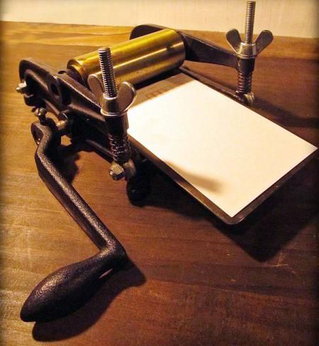
Transparent resin molds experience thermal shock when exposed to higher temperature molten plastic.
Formlabs printed the shape of a USB device case in High Temp Resin to test
| Melting Point | plastics | High Temp Polymer (HDT at 0.45 MPa = 289° C) | Clear Polymer (HDT at 0.45 MPa = 73.1° C) | |
| LDPE | 163 °C | ||
| PP | 177 °C | ||
| TPE | 177 °C | ||
| PLA | 180 °C | ||
| ABS | 204 °C | ||
| HDPE | 204 °C | ||
| EVA | 204 °C | ||
| Polystyrene | 226 °C |
High temperature polymer molds showed no temperature degradation at the mold surface for any of the tested plastics.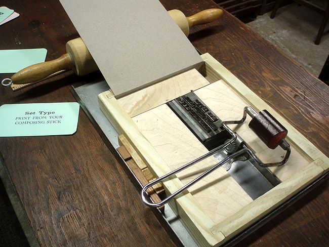
*DURABLE RESIN polymer is under development and final specifications are subject to change.
High Temp and Standard are the polymers best suited for molding. Of the Formlabs resins, High Temp has the highest HDT at 0.45 MPa and low thermal expansion. It is also the stiffest material with the highest stretch factor.
The relatively high stiffness of High Temp Resin means that the mold will not deform when the part is removed. This makes the use of a release agent especially important for removing parts molded from rigid plastics such as polystyrene.
GENERAL TROUBLESHOOTING
Form overflow leak.
Leakage occurs when the injected plastic is forced out between the two mold halves. This can happen when the shape is overflowing, or if the split plane is not completely flat. Adding thin exit ports to the mold can help mitigate leakage from overpressure within the mold, facilitate part removal, and eliminate entrapped air that can cause bubbles in the molded part.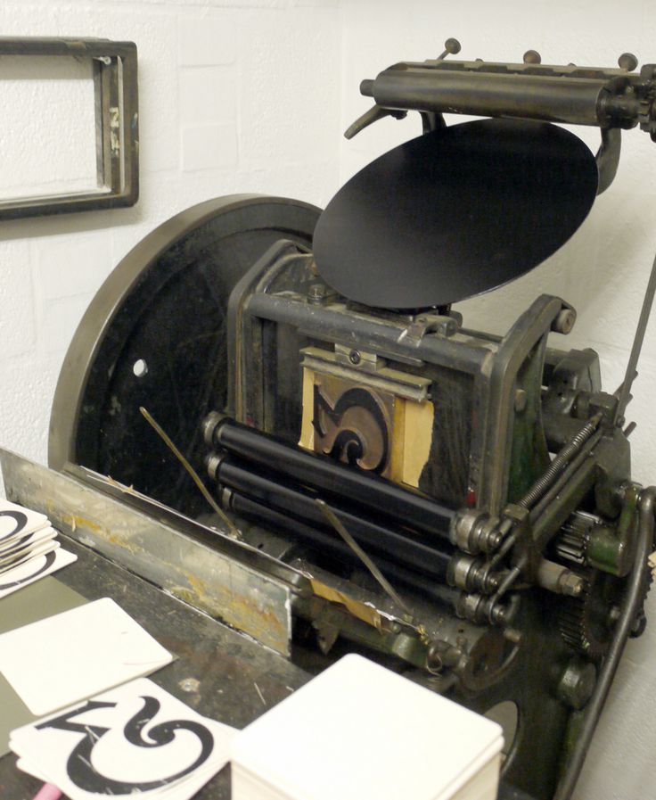 Although not shown, the plates were tested without the aluminum frame. The downside to this approach is that these parts use more material, which increases printing cost and time, and the forms can be more prone to warping. With this method, a steel washer placed between the printing plate and the nozzle of the injection molding machine protects the print from direct contact and helps distribute forces. In addition, pre-sealing the injection molding cylinder against a metal block helps ensure there are no air pockets to disrupt the plastic flow.
Printed lines visible on some parts; this can be reduced by printing the form with a lower layer height. The plates used in this study were printed at 100 µm, but 50 or 25 µm could also be used. This will improve the cleanliness of the plate surface, but increase print time and reduce tank life.
Final USB device case molded from high temperature resin.
DESIGN INSTRUCTIONS.
When designing a form, evaluate what will print successfully, as well as what will successfully form.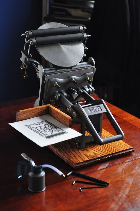
- Adding one to three degrees of recess on surfaces perpendicular to the direction of the recess will allow easier part removal and minimize mold degradation. Fillets should be applied to the inside edges to reduce buckling from internal plastic stress and facilitate removal of the part.
- Embossed and engraved parts must be offset from the surface by at least 1 mm.
- If you plan to use an aluminum frame, The surfaces of the split planes can be polished with fine sandpaper to reduce flare. add an extra 12mm thick plate to the back of the mold plate to account for compressive forces and ensure complete sealing.
- Be sure to orient the mold halves in the PreForm so that the cavity is facing up. This will prevent reference marks inside the cavity and make post-print processing easier.
90° angle
2° recess
Optimum condition 2° recess and round.
PROCESS SUMMARY
STEP 1:
Part design in CAD.