3D printing explained in 37 seconds
3D Printing & Additive Manufacturing Resources
Upcoming WebinarEvaluating 3D Printed Materials in Biomechanical Designs
December 13, 2022
Learn how Biomechanical Engineer, Oliver Grimaldo Ruiz from the Polytechnic Institute of Torino is developing and testing designs using medical 3D printers from Stratasys.
Mehr erfahren
Upcoming WebinarStratasys Origin One Update for Parts Providers
December 07, 2022
Overview of features and benefits of the new Origin One system for parts providers. Covering DLP basics, Origin One system overview, operating software, and materials.
Mehr erfahren
Upcoming WebinarStratasys Neo Stereolithography Update for Parts Providers
November 16, 2022
Overview of features and benefits of the new Neo 450 and 800 SLA systems for parts providers. Covering SLA basics, Neo system overview, operating software, and materials.
Mehr erfahren
Resource GuidePrint consistent parts, time after time, with the SAF™ technology Design Guide
November 09, 2022
This SAF™ technology Design Guide provides how to achieve the best outcome with the advanced options that the h450 printer provides. Download it here.
Mehr erfahren
Blog24/7 automation scaled for the factory floor.
November 04, 2022
Stratasys has developed the P3™ Automated Production Cell prototype to demonstrate how Stratasys P3 (Programmable Photopolymerization) technology can be scaled to a factory-level solution.
Mehr erfahren
WebinarFDM Product Update for Parts Providers
November 02, 2022
Product update of new product offerings in FDM for parts providers. Covering F770, F370CR, and T40 slice thickness for Ultem9085 and N12CF
Mehr erfahren
Case StudyNee Zahntechnik makes smiles shine brighter with Stratasys
October 30, 2022
The Stratasys J5 DentaJet dramatically improves dental lab’s production process
Mehr erfahren
VideoPurple Platypus and Onulis Team Up with Stratasys h450 3D Printer
October 21, 2022
Purple Platypus had the privilege of working with Onulis to create 46 production 3D printed parts for the WRAP machine, using their Stratasys h450 3D Printer.
Mehr erfahren
WebinarWhy Victrex AM200 is a Great Fit for Aerospace Applications
October 20, 2022
Thursday, October 20, 2022 at 11:00 AM CST. Find out why VIctrex AM200 is a great fit for Aerospace Applications.
Mehr erfahren
WebinarResearch and development of the new Sander's Grip with Boeing by University of Washington
October 19, 2022
Join Stratasys and University of Washington as we discuss how researchers created a new handle to reduce the sander vibration with Boeing - from the development of an exclusive digital material to how students worked with 3D printing to get to the final design.
Mehr erfahren
10 von 1113 Ergebnis(se) gezeigt Mehr zeigen
3D printing breakthrough enables custom tablets to be produced in just seven seconds
0Shares
Researchers at the University of Santiago de Compostela, MERLN Institute University College London (UCL) and UCL spin-out FabRx, have come up with a way of 3D printing tablets inside of seven seconds.
As opposed to the normal vat photopolymerization process, which can be used to print pills layer-by-layer, the team’s volumetric printing approach is capable of curing full vats of resin in a single run. In doing so, the scientists say their technology has the potential to ramp up the rate at which custom medication is produced, a USP that could prove vital to making end-use clinical 3D printing more viable.
“This could really be a game-changer for the pharmaceutical industry,” Alvaro Goyanes, one of the UCL scientists behind the project told the i newspaper. “Personalized 3D printed medicines are evolving at a rapid pace. They are starting to reach the clinic for trials and in a best case scenario they could be used in the health service in three to five years.”
A diagram depicting the methodology behind the team’s approach. Image via UCL.FabRx’s custom medication drive
Since 2016, when Aprecia established itself as an early leader in additive manufactured medicine with the launch of fast-dissolving Spiritam, the first FDA-approved 3D printed drug, it’d be fair to say that the technology has come on leaps and bounds.
By 2020, for instance, researchers in Pakistan had proved it possible to 3D print antibiotics with optimized drug-release rates, via fused deposition modeling (FDM) technology and precise infill control. Earlier that year, a team based at St. John’s University also took a similar approach to 3D printing egg-shaped capsules, designed to be difficult to crush by those trying to abuse prescribed opioids.
More recently, FabRx itself has made advances in the field of tailored medicine as well, developing a means of Selective Laser Sintering (SLS) braille-patterned printlets for the visually impaired, as well as launching its M3DIMAKER system.
Marketed as the ‘first pharmaceutical 3D printer for personalized medicines,’ the machine features a multi-nozzle setup that allows users to switch heads and change from FDM to Direct Powder Extrusion production. The start-up also boasts that the system is supported by software that allows it to create prescribed pills on-demand, but this progress hasn’t stopped it iterating upon its technology.
In fact, working with colleagues at Universidade de Santiago de Compostela and UCL late last year, FabRx managed to develop its own smartphone-powered tablet 3D printer. Built around a modified M3DIMAKER, the team’s revised setup proved capable of producing customized blood-thinning capsules, and it was thought at the time that it could be used to improve access to prescribed medication.
Vat polymerization’s speed limit
So, given FabRx’s track record of relative success in 3D printing drugs with custom release profiles, shapes and sizes, why hasn’t it managed to achieve greater traction in the pharmaceutical sector? Well, aside from issues such as gaining regulatory approval and passing the relevant testing procedures, there’s also a commercial drawback to adopting 3D printing in this way: throughput.
According to the UCL-led team, “existing 3D printing technologies don’t afford the speeds required for the on-demand production of medicines in fast-paced clinical settings.” However, the scientists add that volumetric printing “exploits the threshold behavior” that occurs in polymerization to cure masses of resin, hence it may offer a solution to this.
Now, building on the work carried out in their previous study, the researchers have found a way of putting this approach into practice, by manipulating light in such a controlled way, that it can solidify vats of resin simultaneously.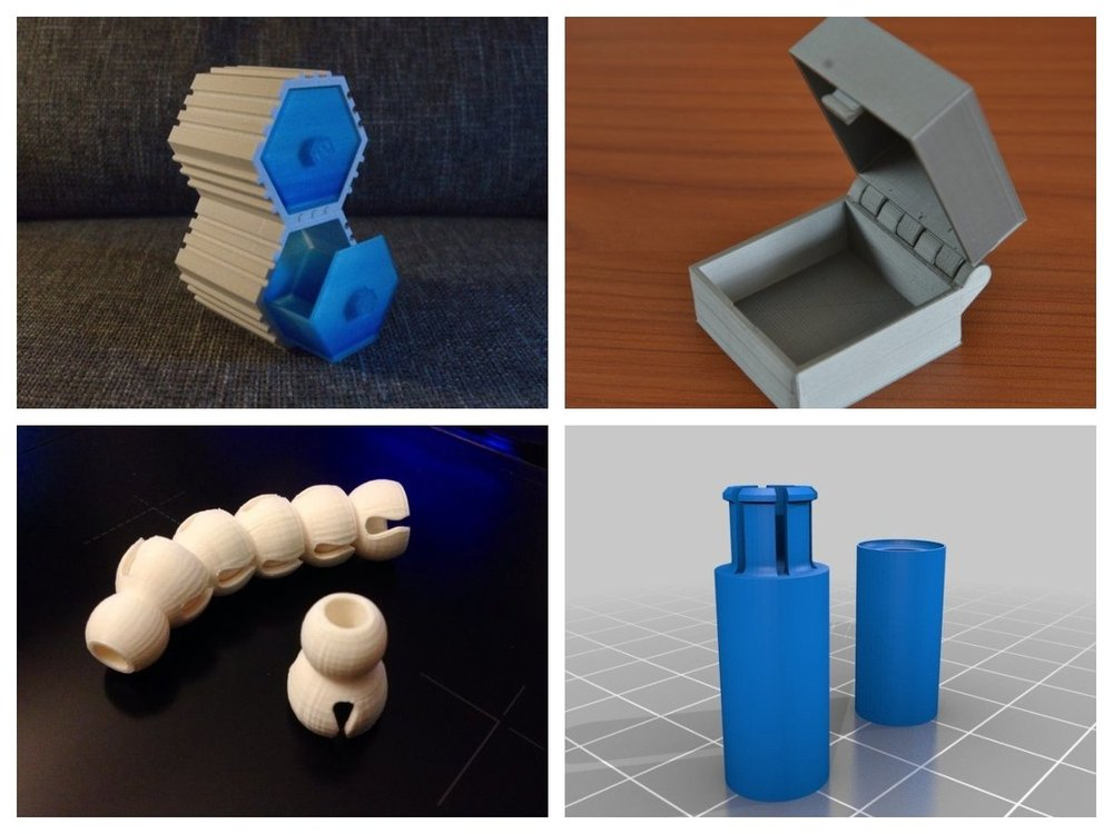 This is said to have been achieved by tweaking the intensity of emitted rays and applying them at various angles, until the full mass of material can be polymerized in one go.
Volumetric 3D printing in-action
During their study, the researchers deployed a modified 3D printer to assess the efficacy of their revised approach, and produce tablets from six different photoinitiator-loaded resins, with paracetamol being used as a model drug. Initial results from these tests showed that the team were able to produce tablets with tunable drug release profiles, at a rate of anything from 7 to 17 seconds per pill.
With further development, the scientists say that their approach could be used to create ‘polypills’ at pace, the likes of which incorporate tailored doses or multiple medications, but tend to come with longer lead times. One application the technology is currently reportedly being trialed in, involves 3D printing cancer therapy and anti-side-effect drugs inside the same pill at a French hospital.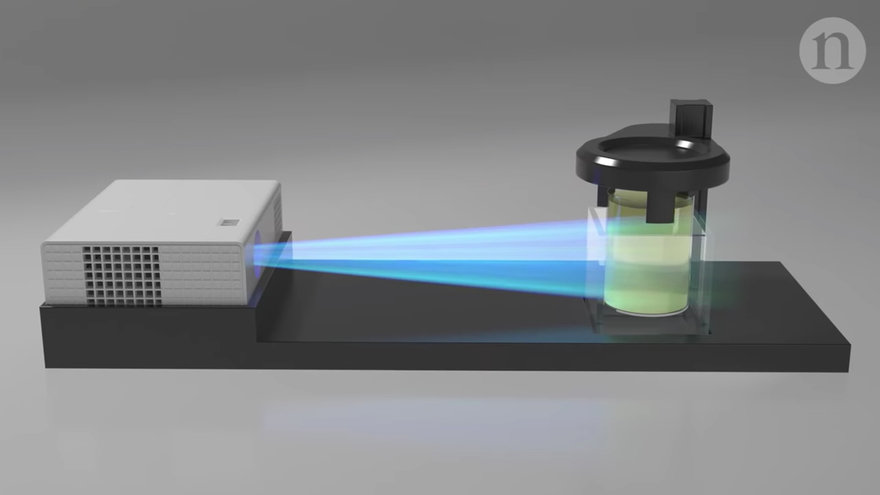
“To reduce the risk of recurrence, many women with early-stage breast cancer are treated with hormone therapy for five years, often with additional treatments to manage side effects,” Maxime Annereau, the Gustave Roussy hospital pharmacist leading the project explained to the i newspaper. “Taking all of these treatments in a single 3D printed tablet with a personalized dose should make it easier to complete the treatment.”
Another potential application of the technology lies in the production of more appetizing medication for poorly kids, especially given that London’s Great Ormond Street Children’s Hospital is said to be weighing up installing a 3D printer at its pharmacy, with its team of specialists there believing that the technology could, in future, become an essential piece of kit.
“I am already looking to put a 3D printer in the pharmacy at GOSH to support trials of use of 3D medicines,” Steve Tomlin, Chief Pharmacist at the Great Ormond Street Children’s Hospital also told the i newspaper.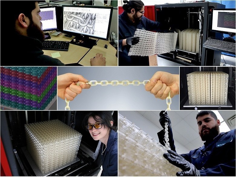 “Knowledge of genetic differences in people’s responses to medicines (pharmacogenomics) means that we know that for many drugs one size does not fit all.”
The researchers’ findings are detailed in their paper titled “Volumetric 3D printing for rapid production of medicines.” The study was co-authored by Lucía Rodríguez-Pombo, Xiaoyan Xu, Alejandro Seijo-Rabina, Jun Jie Ong, Carmen Alvarez-Lorenzo, Carlos Rial, Daniel Nieto, Simon Gaisford, Abdul W. Basit and Alvaro Goyanes.
To stay up to date with the latest 3D printing news, don’t forget to subscribe to the 3D Printing Industry newsletter or follow us on Twitter or liking our page on Facebook.
For a deeper dive into additive manufacturing, you can now subscribe to our Youtube channel, featuring discussion, debriefs, and shots of 3D printing in-action.
Are you looking for a job in the additive manufacturing industry? Visit 3D Printing Jobs for a selection of roles in the industry.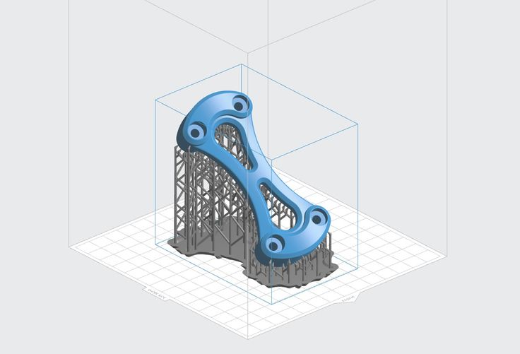
Featured image shows a diagram depicting the methodology behind the team’s approach. Image via UCL.
Tags Alvaro Goyanes aprecia FabRx Gustave Roussy M3DIMAKER Maxime Annereau MERLN Institute for Technology-Inspired Regenerative Medicine St Johns University Steve Tomlin University College London University of Santiago de Compostela
Paul Hanaphy
Paul is a history and journalism graduate with a passion for finding the latest scoop in technology news.
3D printing of mixed propellant / Sudo Null IT News
To start the video.
3D printed propellant blend - we did it. After a hundred experiments, several waves of despair and stages of acceptance of the inevitable. Made and patented.
The developed technology for the additive production of solid propellant charges (SFC) from mixed propellant propellant (SRT) for a solid propellant rocket engine (SRM) using the FDM printing method includes: a special SPT composition with the required energy and operational parameters, the layer-by-layer synthesis 3D printer itself for printing rocket fuel; and several related technologies.
What is all this for?
Yes, then, in order to “disrupt” the rocket and space industry, and in particular, “disrupt” solid rocket science, which makes up 99.9% of all rocket science, and which now suffers from many shortcomings (pains) inherent in the current technology for creating TTZ.
Firstly, 3D printing is devoid of all the shortcomings of modern TTZ manufacturing technologies. The production of mixed solid polymer propellants for solid propellant rocket engines (SSREs) today is represented by casting (vacuum and pressure) and pressing through a matrix. Casting is characterized by all defects of a rheological nature: volumetric shrinkage, lugs, bays, etc.; and pressing has a strict limitation of the geometric parameters of the TTZ and additional operations in the technological process associated with ensuring safety. After casting and pressing, TTZ is usually machined, in most cases by hand. In general, the current technologies for the manufacture of TTZ after the polymerization and cooling process have a large proportion of defects associated with product cracking.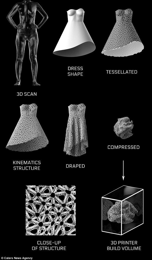 Plus, the need for a huge range of technological equipment for molding combustion channels (profiled needles, multi-piece needles, fingers, etc.). and additional equipment to ensure the tightness of the process (inserts, cuffs, sealing rings), which prevents the liquid mass of explosive fuel from entering the elements of butt joints. It is also necessary to additionally strengthen the body of the product due to the large internal loads on it during polymerization and cooling, resulting in a parasitic mass. Another disadvantage is the time - together with control operations, polymerization can take up to one and a half months. 3D printing of CPT is devoid of such disadvantages.
Secondly, the uniformity and inflexibility of TTZ production. Each application problem solved by an aircraft with a solid propellant rocket engine has its own energy parameters: high-energy rocket boosters and meteorological rockets have different laws of change in thrust over the time of engine operation, therefore, for the manufacture of TTZ for boosters, there is its own technological process, and for meteorological rockets - its own, i.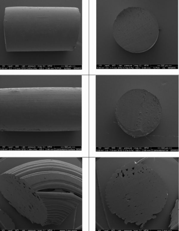 e. Specialization of production is required, with all the ensuing economic difficulties. Controlling the properties of a TTZ at each point in its volume using 3D printing makes it possible to create various TTZs with highly customizable energy characteristics and different dimensions on a relatively small production area for each specific task.
Thirdly, in the general case, the TTZ combustion surface area:
where P(x) is the combustion surface perimeter in the section perpendicular to the longitudinal axis of the charge.
That is, in order to increase the TTZ combustion surface area, on which the solid propellant rocket engine pressure and, as a result, thrust, depend, it is necessary to increase the curvilinearity of the TTZ cross-sectional profile. On fig. 1 shows a TTZ with a complex profile printed on our 3D printer.
The existing technologies for the production of solid propellant charge (SPC) are limited in the creation of complex profiled SPC, which limits the energy characteristics of solid propellant rocket engines.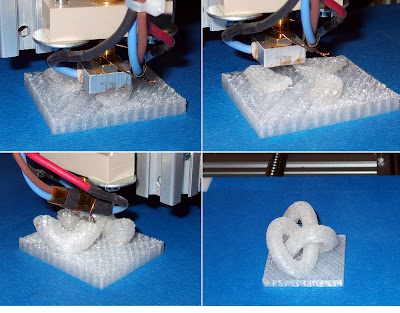 To complicate the curvilinearity of the TTZ cross-sectional profile, a wide range of technological equipment is required.
Even at the dawn of astronautics, engineers developed a number of complex forms of TTZ (Fig. 2), but technologically they could only implement them as experimental samples. Therefore, due to the relative ease of manufacture, the most common type of cross-sectional profile for a solid propellant rocket motor today is a hollow cylinder with a round hole in the center, a typical example of which is the Space Shuttle System solid propellant booster (Fig. 3). By the way, even with such a simple geometry of the combustion channel, the “sidewall” of the Space Shuttle is the most powerful rocket engine in the history of mankind. But what happens if you make a slightly more complex profile using 3D printing in the same form factor?
Fig. 1 - An example of a complex TTZ profile printed on our 3D printer 2 — Dependence of thrust profiles on the curvature of the TTZ combustion channel 3 - "Side" Space Shuttle Fourthly, 3D printing itself is the most robotic technology. For 3D printing, there is no need for a large number of workers in order to assemble / disassemble numerous technological pins, needles and mandrels; wash the mixing tank; cut off excess fuel, etc. Therefore, this technology is much safer. The level of manual labor involved in pouring fuel can be seen in this excellent video.
Fifthly, additive manufacturing technologies make it possible to digitalize the manufacturing process of TTZ, which, in turn, will allow, for the first time, to introduce adaptive business processes of the third wave in the rocket and space industry.
By itself, managing the pairing of each point of the TTZ volume by layer-by-layer synthesis makes it possible and economically justified to widely use digital twin technology, IoT elements and machine learning to improve the quality of the production process.
Particular attention was paid to safety in our project. The design includes many technical solutions that ensure the safety of the process: from modification of the fuel composition to an armored capsule for a few personnel who control the printing.
These are the main advantages of the technology of additive production of TTZ from mixed propellant.
Of course, we are not alone in seeing all these advantages of this technology. In addition to our modest project, this technology, according to open sources, is being worked on in the USA, Great Britain, the Netherlands and China.
In the US, several major research institutes are doing this, such as the Institute of Combustion, Raytheon Technologies Corporation, and a number of technology start-ups of various levels, some of which are commissioned by DARPA, whose visible results are still classified.
On the other hand, a start-up that prints plastic fuel for hybrid rocket engines (HRE) is openly showing its results to everyone. Through 3D printing, they have improved the energy performance of the gas turbine engine.
In general, the Americans are developing this technology under at least two defense contracts: the first is the concept of on-demand payload delivery in the shortest possible time to a given orbit, and the second is a concept that they call “ROCKET FACTORY IN-A- BOX", and according to our project "Expansion" - Autonomous Rocket Plant (ARZ), which I will write about in a separate article - about how 3D printing technology radically transforms the current technological order that has developed in the rocket and space industry, and in particular how additive manufacturing of rocket fuel will change the battlefield (if the editors of Habr give the go-ahead on such a topic).
Further development of the Expansion project
missiles.
The market for small spacecraft launch services is an excellent place for the first stage of expansion. The advantages of 3D-printed solid rocket fuel will make it possible to abandon liquid launch vehicles, which will radically reduce the cost of launching pico / nano satellites.
The current stage of the project is the search for ways of development and scaling.
strength of 3D printer products-Studia3D
05/10/2018 in the expert blog, instructions
UDC 67.02, 620.172.2, 004.9
The study of the strength characteristics of the model material obtained by the FDM printing using the ABS-plastic.
Kamonichkina Natalya Vladimirovna
1st year Master
Department of Materials Processing Technologies
Moscow State Technical University. N.E.Bauman
Supervisor: I.V.Kocheshkov
Ph.D.
Additive technologies are currently one of the most dynamically developing areas of "digital" production. This type of technology has great prospects in the production of engineering products and repair work. Additive technologies are based on the use of 3D printers [1]. Of the seven basic principles of the 3D printing process noted in [1], today the most widespread is the extrusion of a material that is selectively fed through a nozzle or jet. This type of 3D printing in the technical literature is called FDM printing (Fused Deposition Modeling).
The widespread use of FDM printing is explained by the relative cheapness of this type of 3D printers and wide technological capabilities in the production of various types of products. However, it cannot be argued that the strength characteristics of the material of parts obtained using FDM printing correspond to the strength properties of the material of the threads that are used in this case. The application of alternating layers by sequential deposition of filaments leads to the formation of a multilevel physical structure of the material. The formed structure may differ in the anisotropy of properties relative to the direction of laying the threads, the difference in the thicknesses of the stacked layers, the presence of various types of defects, and the peculiarity of the mechanisms of material destruction. The factors listed above affect the strength characteristics of the resulting materials.
The most common materials for FDM printing are plastics. An example of a plastic commonly used in 3D printing is ABS plastic. Therefore, the purpose of this work is to study the strength characteristics of the material obtained by FDM printing using ABS plastic.
Description of the procedure and conditions for the preparation of samples.
The material obtained by FDM printing may have a different structure, but it will necessarily consist of a set of volumes with unidirectionally laid threads. This is determined by the technological features of the implementation of FDM printing. Therefore, in order to determine the strength properties of the material obtained by FDM printing, it is necessary first of all to study the strength of the model material with unidirectionally laid threads. In order to evaluate the strength characteristics of the material and the anisotropy of the properties of the test, it is necessary to carry out tests along and across the direction of laying the threads.
The shape and dimensions of specimens for tensile tests were taken in accordance with GOST 11262-80 “Plastics. Tensile test method”. For research, a sample of the second type was chosen (Fig. 1). 3D printing was carried out using ABS+ plastic monofilament from StrimPlast, supplied according to the Specifications - TU 2291-001-24687042-2016. In accordance with these specifications, the monofilament must have a tensile strength of at least 47 MPa and printing must be carried out in the temperature range of 220-250 0 C.
Fig.1 Sketch of a specimen for tensile testing.
3D printing allows you to immediately produce samples for testing tensile strength, bypassing the stages of obtaining a primary blank and subsequent cutting of samples from it. The thread laying order (G-code) was prepared in the Simplify3D version 4.0 program according to GOST 20999-83 “Numerical control devices for metalworking equipment. Coding information of control programs”, taking into account the location of the threads in the working part of the sample along or across the direction of stretching. FDM printing was carried out on a PicasoDesignerPro250 3D printer with an extruder nozzle diameter of 0.3 mm.
Before printing, to improve the adhesion of the material, the table was covered with a special The3D binder. The temperature of the table was 110 0 C, and the temperature of the extruder nozzle was 240 0 C. Printing was carried out in three modes:
- stacked layer of thread h sl =100 microns;
- Mode 2 : at extruder nozzle speed V s =45 mm/s and the thickness of the stacked layer of thread h sl =150 µm;
- Mode 3 : at the speed of movement of the extruder nozzle V s =60 mm/sec and the thickness of the stacked layer of thread h sl =200 µm;
The obtained specimens were tested for tension at the rate of extension of the clamps of the testing machine corresponding to 1±0. 5 mm/sec (the minimum rate of extension of the clamps of the testing machine provided by GOST 11262-80).
Discussion of the obtained experimental data.
Experimental data on the results of testing the material obtained by FDM printing using ABS, along and across the filament laying, are shown in fig. 2. From the presented data, it can be seen that the tensile strength of the material obtained by all three 3D printing modes in the direction of laying the threads is close in its values and is at the level of 31-33.5 MPa. If we use the manufacturer's data on the strength of the monofilament used in FDM printing (47 MPa), then these values are approximately 31% lower. However, in order to conduct a more correct comparison of the strength levels of these two materials, it is necessary to clarify to what extent the conditions for testing monofilaments coincide with the conditions for their loading in the model material.
The strength of the model material across the threads is significantly lower and depends more on the FDM printing modes (Fig. 2). The speed of movement of the extruder nozzle in combination with the thickness of the laid layer affect the adhesion strength of the threads. This is due to the spread of heat from the nozzle into the material. At high print speeds, less heat is transferred to the plastic at any given point in time than at low speeds. If you print a small layer at a low speed, then too much heat may be given off. This will increase adhesion, but there will be a possibility of defects in the form of plastic sagging. Conversely, if you are 3D printing with a thicker layer at high speed, there may not be enough heat to form good adhesion between the filaments.
This assumption is confirmed by the obtained experimental data (Fig. 2). In mode 1 (minimum printing speed and thickness of the stacked layer), the strength of the model material across the laying of threads is maximum and amounts to 20.2 MPa (67% of the material strength along the laying of threads), in mode 2 - 14 MPa (41% of the material strength along laying of threads) and in mode 3 - 15. 9 MPa (51% of the strength of the material along the laying of threads). That is, when switching from mode 1 to mode 2 of 3D printing, there is a decrease in tensile strength of samples with cross-laid filaments, as a result of a stronger influence of the increased thickness of the stacked layer of filaments than an increase in printing speed. And when switching from mode 2 to mode 3, the increase in printing speed has a predominant effect, which leads to a slight increase in the strength of the material (Fig. 2).
Fig. Fig. 2 Dependence of tensile strength σ r of the model material with longitudinal and transverse filament laying obtained in different 3D printing modes (Mode 1 – V s =30mm/s, h sl =100 µm; Mode 2 – V s =45 mm/s, h sl =150 µm Mode 3 - V s =60 mm/s, h sl =200 µm have a different type of tensile diagram and fracture surface. If the tensile diagram of samples with transverse filament laying has a characteristic form for brittle fracture, then on the tensile diagram of samples with longitudinal fiber laying, after a slight decrease in the tensile force, after reaching a maximum, its gradual decrease is observed until the moment of sample failure.
Fig. 3 The nature of the destruction of samples with transverse (a) and longitudinal (b) laying of threads.
Samples with transverse fiber laying (Fig. 3a) have an absolutely flat fracture surface, while specimens with longitudinal fiber laying (Fig. 3b) have a developed fracture surface. When examining these fractures with an optical microscope, it can be seen that the destruction of the material with transversely laid fibers occurs in one plane (Fig. 4a) along the surface of the laid filaments. The fracture of the model material with the longitudinal laying of fibers (Fig. 4b) has a developed character. Fracture proceeds in different planes, and both areas of damage accumulation and flat zones characteristic of the main crack propagation are observed at the fracture.
Fig. Fig. 4 Fracture view of samples with transverse (a) and longitudinal (b) laying of threads.
Conclusion
- For the model material obtained by FDM printing using ABS plastic, when laying threads along the load application direction, no dependence of tensile strength on 3D printing modes was revealed.
 The strength in all printing modes was 31-33.5 MPa, which is approximately 31% lower than the strength of monofilaments declared by the manufacturer.
 - The strength of cross-laid pattern material is 41-67% of the strength obtained when tested along the fibers. This strength depends on the modes of 3D printing. The maximum value - 20.2 MPa - was obtained in mode 1, at the speed of the extruder nozzle V s = 30 mm/sec and the thickness of the stacked layer of thread h sl = 100 μm, and the minimum value - 14 MPa - is observed in the mode 2, at V c =30 mm/sec and h sl =100 µm.
- Samples of model material with longitudinal and transverse laying of threads have a different nature and type of fracture surface:
- during their transverse laying, an absolutely flat fracture surface is observed along the junction of the deposited threads, and, therefore, the amount of adhesion between them is the most important factor affecting the strength value;
- during their longitudinal laying, the fracture of the material has a developed character, both with areas of damage accumulation and with zones of main crack propagation.