3D printing design guidelines
What are the key design elements for 3D printing?
Are you new to designing parts for 3D print manufacturing or need a refresher on essential design elements? This article provides the key design elements for creating digital models for 3D printing, no matter the additive manufacturing process.
Every 3D printing technology comes with a distinct set of capabilities and its own design freedoms and restrictions. Whether you are a seasoned engineer who’s well-versed in designing for 3D printing or you are new to the field, it’s always a good idea to go over the most essential factors that make or break a design.
This article covers the key design considerations that apply to 3D printing in general, regardless of the printer you choose for manufacturing your custom parts.
Check out this handy infographic for quick access to every essential design element you may need while creating digital models to 3D print.
Each 3D printing process has its own design advantages as well as some limitations. Let’s break down the key design considerations that apply to every 3D printing technology to keep in mind when designing your next custom parts.
All 3D printing processes build parts layer-by-layer. New layers can’t be deposited onto thin air, so every layer must be printed over some underlining material.
Overhangs are areas of a model that are either partially supported by the layer below or not supported at all. There is a limit on the angle every printer can produce without the need for support material. For example, if you’re printing with an FDM and SLA machine, this angle is approximately 45 degrees .
We recommend limiting your model’s overhangs, as layers printed over support structures usually come out with a rougher surface finish.
This image shows the effect of increasing angle on overhang quality for FDM printingWall thickness for 3D printing
The second thing to keep in mind when designing a part to be 3D printed is wall thickness. Every 3D printing process has its own level of precision. FDM, for instance, is the least accurate, while SLA has the tightest tolerances. In terms of part stability, every 3D printing process has a lower limit regarding wall thickness and feature size.
For example, imagine you are an engineer designing a new generation of hang gliders. You’ve chosen to 3D print a scaled-down version of the product to test its efficacy. 3D modeling programs allow you to model the sailcloth of the wing, for instance, but you then encounter problems when you would try to 3D print it. This is because the model’s wall thickness is less than the minimum required for successful printing.
It’s essential to make sure that your 3D designs have walls that meet the minimum required thickness for the printing process you choose. All 3D printers can successfully print components with wall thicknesses greater than 0.8 mm.
What is warping and how can you avoid it?
Something that is often easily overlooked while designing a 3D model is the fact that the materials used for 3D printing undertake physical change: they are melted, sintered or scanned with a laser and solidified.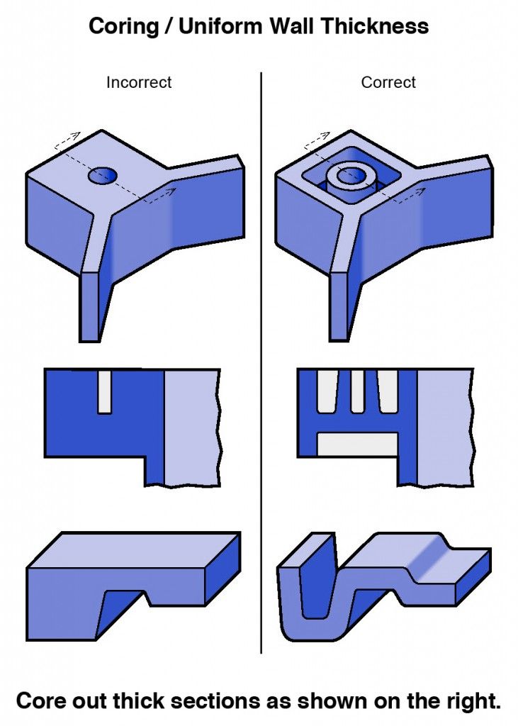 The heating and cooling of material can cause the parts to warp while printing.
Large, flat surfaces can be especially prone to warping. Warping can typically be avoided by using correct machine calibration and having adequate surface adhesion between your part and the print bed. A good practice is to avoid large flat surfaces and add rounded corners to your 3D models.
When you are creating a 3D model with intricate details, it is important to keep in mind the minimum feature size each 3D printing process can handle. The minimum level of detail is connected to the capabilities and mechanics of each 3D printing process and to the selected layer height .
The process and materials used will have an impact on the speed and cost of your print, so determining whether smaller details are critical to your model is an important design decision.
The most important thing to remember while designing for 3D printing is the fact that your digital design will become a physical object. In the digital design environment, there are no laws of physics to adhere to, such as gravity.
Anything can be "drawn" in 3D on a digital canvas, but not everything can be 3D printed. Knowing the key factors that go into designing 3D models will ensure that you produce digital designs that can be successfully printed.
Want to learn the key design elements for every 3D printing technology?
Design parts for FDM Design parts for SLA Design parts for SLS
Ready to transform your CAD file into a custom part? Upload your designs for a free, instant quote.
Get an instant quote3D Printing Design Guidelines - JLCPCB: Help & Support
1. Wall Thickness
3D Printing process needs to go through alcohol cleaning, supports removing, grinding, sandblasting and so on. So the model needs a certain strength, and the thickness determines the strength of the parts.
In 3D Printing, wall thickness refers to the distance between one surface of your part and the opposite sheer surface. A part made by 3D printing has a minimum wall thickness that is dependent on its overall size. As a guide, we recommend that you increase your wall thickness whenever you scale up your design to a larger size.
2. Embossed and Engraved Details
Min. Embossed Detail
LEDO6060/8000/9000R/8228/Black Resin : 0.5 mm deep & 0.5 mm wide
PA12: 0.5 mm deep & 0.5 mm wide
PAC: 0.8 mm deep & 0.8 mm wide
3201PA-F : 0.8 mm deep & 0.8 mm wide
ABS: 1.0 mm deep & 1.0 mm wide
316L: 1.0 mm deep & 1.0 mm wide
Min. Engraved Detail
LEDO6060/8000/9000R/8228/Black Resin: 0.5 mm deep & 0.5 mm wide
PA12: 0.5 mm deep & 0.5 mm wide
PAC: 0.8 mm deep & 0.8 mm wide
3201PA-F : 0.8 mm deep & 0.8 mm wide
ABS: 1. 0 mm deep & 1.0 mm wide
316L: 1.0 mm deep & 1.0 mm wide
3. Thread design
There are two main factors affecting 3D printing of non-standard threads: thread pitch and Helix angle.
The clearance fit of thread needs to refer to model clearance. If there is no clearance fit in the design, it will be unable to assemble. The minimum standard screw is M6.
4. Model clearance
Clearance between parts that will be assembled together
Modules can be printed to be assembled, as long as they meet the minimum clearance as shown below.
Clearance between moving parts
The minimum clearance between two moving or connecting parts.
The above is the minimum clearance for simple structures, which is not applicable to all structures.
5. Escape Holes
Hollow designs need an “escape hole”, so that excess material can escape during the 3D printing process. Most printing services use printers and printing techniques that require at least one escape hole.
(1) The minimum escape hole diameter is 2.5mm.
(2) Two escape holes are required when the escape hole diameter is less than 3mm, otherwise the resin will not flow out and the cavity will not be cleaned, and the part may crack after a period of time.
(3) The size and quantity of escape holes shall be finally determined according to the model size and structure.
(4) The supports in the cavity cannot be totally removed unless the escape hole is designed to be large enough.
6. Holes design
The relationship between aperture (Φ) and hole depth (h):
When the model is designed with micropores and deep holes, please refer to the above standards.
7. Small column design
The relationship between column diameter (D) and column height (H):
When the model is designed with a positioning column, please refer to the above standards.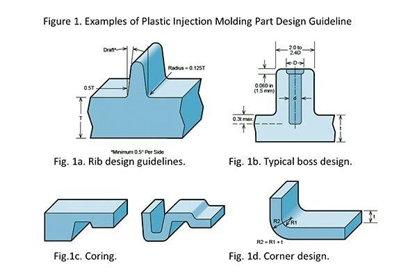
8. Special-shaped model
The special-shaped model is mainly hollow structure, which occupies a large space, as shown in the following figure.
When it is designed as a special-shaped part and meets the printing requirements, a certain special cost will be appropriately charged.
9. 3D Printing Tolerances
Resin materials: ±0.2mm or within 0.3%
Nylon materials: ±0.3mm or 0.4%
316L : ±0.2mm or within 0.3%
ABS : ± 0.3mm or within 0.4%
Tolerance changes over time:
10. Multiple same parts design
Max 10pcs same small parts could be supported in 1 file, but all the separate parts should be connected and combined in 1 large part (1 shell) to proceed and the wall thickness of the connection area should be more than 1.5mm. Please kindly note: FDM with ABS material and SLM with 316L material are not supported in this way.
short tips for the transition from a CAD model to a printed object / Sudo Null IT News
was withdrawn from publication due to a technical error.Please be understanding. Thank you!
Whether it's just a hobby or a source of income, 3D printing is always based on product design. Those accustomed to traditional technologies will have to rethink the entire approach to product design and manufacture.
When the project is ready, a number of additional operations are performed: setting the orientation of the model and other parameters that ensure the proper printing process. In addition, it is necessary to take into account the fact that most 3D printers allow you to choose the degree of filling the model with cellular structures. The correct choice of this parameter provides protection of the object from deformation and destruction during the printing process, as well as significant savings in material and reduction in production time.
Finally, the last factor influencing the success or failure of the 3D printing process is the strength of the connection between the model and the table. If the workpiece is separated from the table during printing, then all the work will go down the drain.
Here, we'll walk you through the 3D printing process and give you some simple tips on how to use additive manufacturing in the design phase. In addition, we will dwell on the methods of preparing a finished project for printing, and also consider ways to securely fasten the workpiece to the table.
These guidelines apply primarily to Fused Deposition Printers (FDM) printers, but may apply to other types of printers as well. The process of obtaining a finished part by 3D printing is basically the same regardless of the method used.
Designing an object
Any 3D printing starts with construction. If you are developing a product yourself, then you need to build a 3D model of it in a computer-aided design (CAD) system to turn the designer's idea into reality. In this case, the object can be both very simple and very complex. However, too thin and too small models should be avoided.
3D-CAD from Siemens from this article for 49900r (90% discount), the promotion is valid until March 20, 2020. Read more>>
Saving the file in a special format for printing
To print an object, its model must be saved in a special file format - for example, STL, which has become the de facto standard in the world of 3D printing. In this format, model surfaces are represented as a grid of triangles. Simple surfaces are broken down into a small number of triangles. The more complex the surface, the more triangles you will need. Today, other formats are used in 3D printing, in particular, the 3MF format developed by Microsoft. But the most common is still STL.
CAD systems make it very easy to save the model in the desired format: just click the Save As command. To improve print quality, it is desirable to set a number of settings for saving to the STL format - for example, the tolerance during transformation and the angle of the plane. The lower the conversion factor and the better the angle, the smoother the printed part will be.
Opening the file in the slicer program
Most, if not all, 3D printers come with their own slicer software. The slicer loads the STL file created in the CAD system and cuts it into layers, and then creates a control program for the printer.
Place the model correctly in the print space
After entering the print settings, the model (or several models) needs to be placed on the printer table. You can print many objects on one table at once. At the same time, compared to printing a single object, the time slightly increases, but in general it still turns out to be less. Here are some tips for choosing the right model orientation.
Set parameters
In the slicer program, the user sets parameters such as print speed, material consumption, nozzle and desktop temperatures. Most slicers have simple settings for beginners. In this case, most often there are also advanced settings so that experienced professionals can achieve optimal results. Advanced settings include percentage infill, amount of backing material, and type of backing or raft (this is a small, thin base that keeps the printed part stable. The backing is removed when it's finished). The number of options is truly endless. Specific settings vary depending on the brand of printer. It's easy enough to set them up.
Sending the control program to the printer
After setting the print settings, the placement of future objects on the table, their orientation and quality, it's time to finally start the printer. It is enough to press the Print button and find something to do while the production is in progress. Depending on the complexity of the design, the process takes from several minutes to several hours.
Finishing
Finishing includes removing the printed part from the table, as well as removing the support material by melting, mechanical separation or dissolution (depending on the design of the printer). The part may require some light sanding or polishing, but overall a properly printed object looks good from the start. Other types of finishing are placing plastic parts in a container with acetone to smooth out surface roughness, gluing (if the dimensions of the structure exceed the dimensions of the 3D printer or individual elements of the object must have different orientations), drilling holes and painting.
3D printing process
3D printer design considerations
Eliminate sharp corners
If the direction of the surfaces changes abruptly (for example, a vertical wall intersects with a horizontal overlap), then such a model is difficult to print. The printer will build excessive inner surfaces, wasting too much material. There are two easy ways to prevent this: add chamfers to smooth out where the surfaces meet, or round the corners so the printer gradually builds a vertical surface. In addition, rounding will increase strength, since destruction most often occurs at sharp corners.
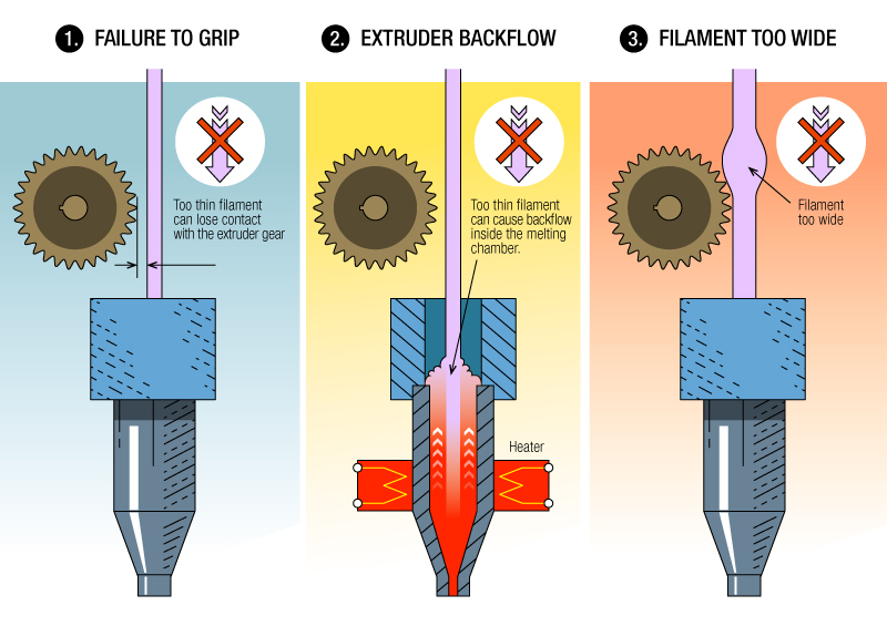
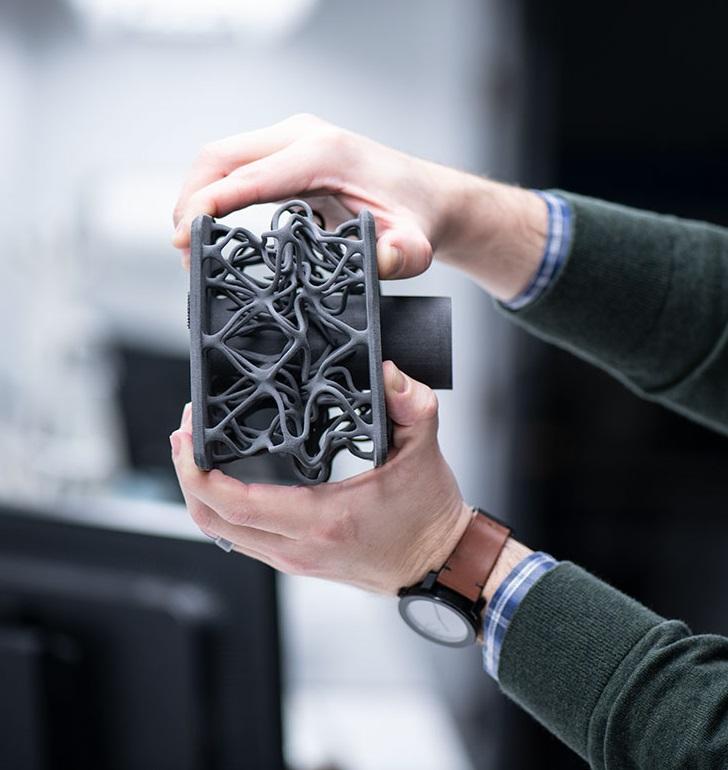
Elimination of thin walls and small geometries
Layer by layer fusing technology consists in supplying hot plastic through a nozzle with the formation of a printed object layer by layer. The thickness of the extruded plastic layer cannot be made smaller than a certain limit, depending on the diameter of the nozzle and the speed of the print head. Excessively thin-walled details are difficult to print - often the result is a chaotic weave of fibers. If the part can be printed, it is very fragile and breaks easily.
Too thick walls - also bad
On the other hand, if the walls are too thick, they become brittle and crack easily. This is especially important when printing from materials other than resins, as excess thickness during the manufacturing process leads to internal stresses in the part. Even when printing from plastics, material is wasted on walls that are too thick and time is wasted.
Removing large overhangs
3D printers allow you to create amazing shapes and surfaces, but they are not capable of printing directly in the air. If there is a void in the part with material above it, additional support material must be used. Most slicers add material automatically, but require you to specify the orientation and volume of the support structure. Printers with a single nozzle create an array of thin columns, which then have to be broken off. The result is an uneven surface. Therefore, it is recommended to avoid large overhanging elements whenever possible in order to reduce the need for support material.
If such an element is unavoidable, you can try to flip the object. Most printers are capable of printing overhanging elements with an angle of about 45 degrees. At a certain height, the edge of such an element may sag somewhat. The actual capabilities of a particular printer are determined by trial and error.
Holes shrink
Remember that the part is made of heated plastic. As it cools, it inevitably shrinks. Therefore, holes and other critical structural elements have to be made larger so that after shrinkage their size is as close as possible to the required one.
However, if you need to make a tight tolerance hole, it is better to print it with a smaller diameter and then ream it with a suitable tool. This is especially true for holes whose axis is parallel to the printer table.
Increasing the footprint
If the area of contact between the object and the base is small, the part may separate from the table during printing. To prevent this from happening, wide bases are added to the model legs, which are installed on the printer table. In general, the closer to the table, the more material must be added to the support.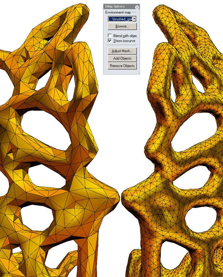 There are other ways to securely fasten the part to the table, which we will discuss a little later.
Special moves
The right approach to design makes printing easier. In addition, there are special post-processing techniques that are important to be aware of.
Place round surfaces vertically
The model should be oriented so that the minimum amount of support material is used. Ideally, it should rest on the table with a large flat edge. In addition, circular geometry must be placed so that the circular faces are vertical. If we look at the printer table from above, we should see a round silhouette of the object. In this case, the part comes out as symmetrical as possible with the formation of a solid round structure.
Place voids and holes vertically
If there are voids in the model (for example, it is a rectangular pipe), it is desirable to place such voids vertically in order to reduce the volume of the support material.![]() If you print the pipe in a horizontal position, you will have to provide support for the entire inside. If you put the pipe on the end, then no support is required at all.
If you print the pipe in a horizontal position, you will have to provide support for the entire inside. If you put the pipe on the end, then no support is required at all.
The same is true for holes: to get a hole with a straight axis, it is best to print it vertically - in the form of a stack of rings, which avoids warping or deforming a round hole into an oval one.
Set print quality settings
Proper selection of print parameters, such as STL conversion tolerance and slicer software settings, allows parts to be produced with a surface quality that matches that of cutting. However, this entails an increase in print time. When choosing quality parameters, one should proceed from the purpose of the object: is it a finished product or a prototype? Will the part be visible or hidden?
The quality parameters also affect the shape of the holes in the part. In CAD files, holes are represented as a set of straight lines at an angle to each other.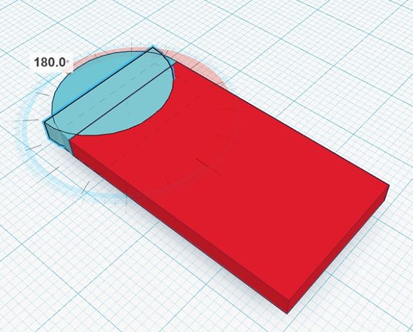 The higher the quality of the model in the saved STL file, the less the circle looks like a polygon.
Reducing the layer thickness
To obtain the best quality, especially when using layer-by-layer deposition technology, it is necessary to reduce the thickness of the layers. It does increase the print time, but the end result is worth it!
Optimizing the filling with honeycomb structures
In terms of strength, objects do not have to be solid. Similar to a honeycomb, printers can create a honeycomb infill that balances strength and saves expensive polymer material. However, if the printed part serves as a prototype for strength testing, and the serial product will be manufactured by traditional methods, and also if the part is subjected to certain types of mechanical stresses and pressures, a solid design will be preferable.
Choosing a material
The success of printing largely depends on the correct choice of material.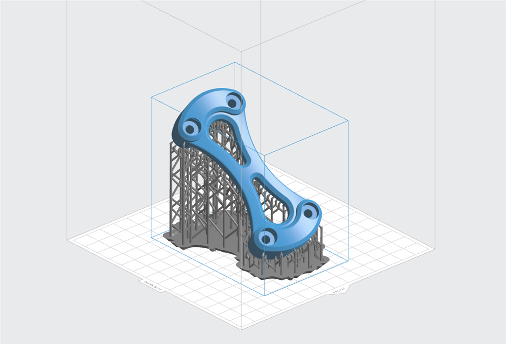 Materials have different properties. For example, the melting point of thermoplastic polyurethane (TPU) and polylactic acid (PLA) is lower than that of acrylonitrile butadiene styrene (ABS). In addition, the material is taken into account when choosing the type of support structures. For an object made of polylactic acid, supporting elements can be made from the same polylactic acid, since it will be quite easy to separate them from the finished part. If the part is printed from ABS plastic, then the support elements must be made from a different material, and it is better not to use such elements at all in thermoplastic polyurethane parts.
Cellular filling
A solid body is not always the best choice for 3D printing. Printing solid parts has its advantages, but the internal honeycomb structure saves both expensive material and time.
Creating objects with a specified degree of filling with honeycomb structures is a unique opportunity for 3D printing. Moreover, it is not required to design such a structure: this is done by the slicer program. As a rule, it is enough to set only the percentage of filling (the closer it is to 100, the more solid the object will turn out) and select the type of cells, if the printer has such an opportunity.
In addition to saving time and material, the internal honeycomb structure has many other advantages.
Cellular filling prevents warpage
Printing large objects as a single piece introduces a danger of warpage. By reducing the infill percentage, the air during printing passes through the part, providing more uniform cooling and eliminating warping.
Cellular filling does not lead to loss of strength
Printing cells instead of solid material does not reduce the strength of the part. In many cases, a honeycomb part is strong enough for the chosen application, but lighter and less material intensive.
The function determines the choice of cell geometry
Most slicers support a wide variety of cell geometries. The optimal option is determined by the functional purpose of the object. Standard box padding simplifies printing, while hexagonal and triangular boxes add strength. Wave fill allows the object to bend or twist.
How to choose the right filling percentage?
In general, the strength of an object increases as the percentage of infill increases. Most printers have a default infill percentage of 20, which is optimal in some cases but too high or too low in others. Consider mechanical stresses in the printed object and increase the percentage of infill in areas where greater strength is required. If high strength is not required, choose the lowest possible filling. This saves material and speeds up printing. Most often, the selection of the optimal percentage of filling is done by trial and error.
Ways of fastening the workpiece to the table
“Rafts”, “brims”, “skirts” – these terms sound funny, but they just refer to the three main ways of attaching a 3D printed part to a printer table. Let's take a look at each of these methods and their areas of application.
Skirt
The skirt involves creating a few rings around the object at the beginning of the print to make sure the plastic is extruded normally. The skirt is not in contact with the object at all. It surrounds the printable area and helps start the fusing process. When creating a skirt, a large volume of hot thermoplastic polymer passes through the nozzle. This prepares the printer for printing the part itself. This guarantees good adhesion to the table and obtaining smooth surfaces of the object.
Brim
The brim is a wide, flat area connected to the main object as a support base (think of a brim of a hat). It is very similar to a skirt, but connected to the model. In addition to all the advantages of a skirt, the brim keeps the edges of the object being made on the table.
When printing, the outside of an object often cools faster than the middle, causing the edges to curl. Brim prevents this phenomenon by holding the edges.
Raft
A raft is a detachable base, made in the form of a thin mesh platform, located under the entire object (which lies on the raft). To create a raft, the printer first prints a flat plate in two or three layers, and then begins to manufacture the object.
The rafts provide excellent adhesion to the table surface and also provide a strong print base. This is especially useful when making small and oddly shaped parts that do not fit well on the table, as well as thin-walled objects.
After printing is completed, in most cases the raft will separate easily from the part.
If the printer does not have a heated desktop function
Rafts are used if the printer does not have desktop heating. In this case, excessive adhesion becomes a problem.
An alternative method is to apply adhesive paper tape to the printer bed, with the edges down if possible (this also protects the bed). You can also use packing tape, but it is usually more expensive.
If buckling does occur or the object separates from the table, apply a dissolvable glue stick to the adhesive tape. This will enhance adhesion.
Find out the features of a specific 3D printer and take them into account when preparing a model
3D printing is not only a science, but also an art. Effective design for subsequent 3D printing requires an understanding of the technological process, taking into account its features and the purpose of the future object. This will greatly improve print performance.
Using Solid Edge in 3D printing
Not all CAD systems are suitable for 3D printing
The capabilities of the applied system should not limit the designers. Our Solid Edge system is designed with the latest 3D printing technologies in mind. Various 3D printers and 3D printing services are supported.
Take it to the next level with specific techniques for designing 3D printed parts
Generative modeling in Solid Edge opens up new possibilities: the designer selects a specific material, sets the design space, allowable loads, restrictions and target mass of the part, and the system automatically calculates the desired geometry. As a result, 3D printing methods can produce the most complex shapes.
In addition, when building models, the use of the results of three-dimensional scanning is provided. Solid Edge successfully combines the traditional boundary representation of solid models (B-Rep) and the representation of surfaces in the form of a grid of triangles, which avoids time-consuming transformations that are fraught with errors.
If you've already downloaded an STL file for printing, our unique synchronous technology makes it quick and easy to edit your imported models in Solid Edge in preparation for the process.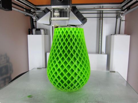
Printing with your own printer or submitting an order to a 3D printing service provider
Printing in Solid Edge on a local 3D printer is done using the 3D print command. Models can be saved in STL and 3MF formats, or sent directly to Microsoft 3D Builder. If you don't have your own 3D printer or need to try out different materials and surface finishes, Solid Edge allows you to directly submit your models to cloud-based 3D printing services (such as 3YOURMIND). You immediately receive quotes for the production of parts from various materials with its subsequent delivery directly to your door.
3D-CAD from Siemens from this article for 49900r (90% discount), the promotion is valid until March 20, 2020. Read More>>
Architectural 3D Printing Modeling Strategy and Software Usage Guide
At a Glance
3D printing provides tremendous benefits to the conventional architectural workflow. You can print complex designs without the need for skilled craftsmen, and quickly modify these designs without too much difficulty.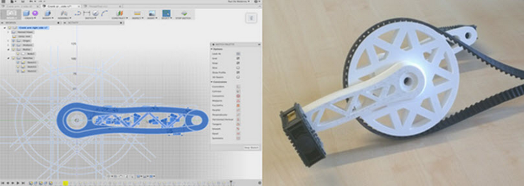 Stereolithographic (SLA) 3D printing delivers incredibly high surface quality and detail, making it suitable for architectural applications. This paper explores modeling strategies and software workflows that enable architects and designers to easily integrate 3D printing into existing design methodology, create best practices based on internal testing by Formlabs and architecture firms, successfully using Form 2 to create 9 models0008
WHAT YOU WILL LEARN:
Strategies for designing 3D printed architectural models
Tips for improving your workflow Pre-print processing software
- Building Information Model (Revit, ArchiCAD)
- Surface modeling (Rhino, SketchUp)
Good post-processing techniques
- Compound
- Finishing
Introduction
The 3D printing market today offers affordable options in both price and scale. While professional-grade technology used to be costly, desktop stereolithography 3D printers allow architects, designers, and model makers to offer high-quality, in-house fabricated parts.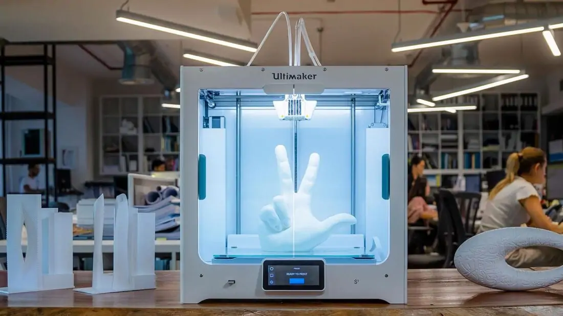
Most models cost less than $10 per part.
3D printing opens the door to creating complex designs with less effort and fewer materials, but the successful transition from a CAD model to a printable file is based on a basic understanding of design for 3D printing. This document will help you understand how standard modeling constraints relate to preparing a file for 3D printing, as well as approaches and decision making for intelligent modeling - from scale selection to design and assembly for post-processing.
To integrate these strategies into existing workflows, this booklet explores ways to approach modeling strategies tactically by examining three of the most common software ecosystems: allows you to include small details even on the smallest models. This example of a small city model has a scale of 1/32″ = 1’ and is completely printed on a Form 2 3D printer. Many small details and parts of this design will take significantly longer if cut and assembled by hand. Model from LaneyLA Inc.
This auditorium section was 3D printed as one piece on a black resin Form 2. Model from DLR Group.
Modeling strategy
Architectural models are usually assembled using various materials and components. 3D printers help combine these components into as few separate parts as possible, but assembly manipulation is still necessary for two reasons:
- Build Volume Limitations: Printers with large build volumes are either expensive or compromise on surface quality. Form 2 build volume is 57 x 57 x 69 inches (145 x 145 x 175 mm)
- Need to show interior details or materiality : Some models require components to be separated to show more design information.
DESIGN FOR ASSEMBLY
All 3D models require preparation before they can be sent to the 3D printer.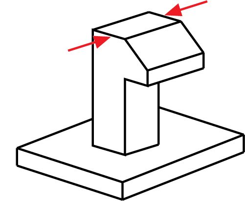 In the case of architectural models for the Form 2, this often involves splitting the model into smaller parts to fit the scope of the Form 2 build. The parts can then be easily joined together by chemical adhesive or mechanical assembly; high precision printing ensures that the parts fit together.
Dimensioning for parts to be separated must take into account the final orientation of the model. Most architectural prints need to be oriented at a 45 degree angle due to floor slabs being considered large horizontal projections. Dividing the model into long, thin parts helps maximize the diagonal length of the build volume while achieving perfect orientation
Strategy overview
There are several strategies for assembling 3D printed models. Your strategy will depend on what you hope to represent with the design, as well as the scale and geometry of the model. Consider the following parameters:
- Need to show internal or external parts
- Split Ease (You want to split the model by the least complex part of the model)
It is necessary to show a certain part of the program: typology, structure, floor layout
| Seam separation | Separation by component |
| Section model | Separation by program |
| Straight cut | Separation by structure |
| Aligners |
Splitting at a seam
STRAIGHT CUT
The easiest way to split a model is with a straight cut. This is a simple command to execute in most CAD software. The bridge model is divided lengthwise using straight cuts into four parts, one of which is shown above. Each support post is inserted into
mating hole that does not require glue. Regardless of which method you choose, if you have a large number of parts (more than 10), it can be helpful to add a unique identifier for each part to help solve the puzzle during assembly.
Pros:
- Least heavy use of CAD
- Greater tolerance for prints that warp or have a higher degree of dimensional change
Cons:
- Assembly requires manually leveling each piece and fixing it in place until the adhesive is fully bonded
Try to print all components in the same orientation so that the layer lines and subsequent dimensional inaccuracies follow the same pattern.
ALIGNMENT TOOLS
Another approach is to add features to the design that will allow the prints to align. When adding mate fixtures, try to subdivide the model in areas with the least complex geometry. Use the CAD tool of your choice to split your model and add basic alignment fixtures such as slots, pins, grooves, recesses and flanges, or more complex fixtures such as dovetails and cuts that follow existing model curves. In addition, it is important to create a design with ~0.25 mm tolerance between mating parts to prevent additional sanding at the post-printing stage.
Pros:
- Easy alignment Parts that are not accurate
- Easy to assemble (mating parts help create a large surface area for adhesion)
- High precision SLA allows tight fit with high tolerance and can be used without adhesive
Cons:
- Parts that are not true to size will not fit well. High fine details are often less accurate.
SECTION MODEL
The separation of the model with a seam has the additional task of showing the section model for structures with irresistible interior details. Initially, the model can be presented as a whole to the client, and then disassembled to reveal interior details as desired. These LaneyLA examples show how the same model conveys different types of information based on open and closed configurations
This LaneyLA model was printed on Form 2 white resin.
Using devices for combining: Methods component
SOFTWARE DIVISION
By splitting a building with software, you can represent the building as a set of parts, providing a clear understanding of all design components without a plan and section drawings. You can print each floor slab separately and then assemble using mates, or just print one component of the entire building separately from the rest. A good example is the model from Stanley Sitetowitz | Natoma Architects Inc (SSNAI), who used the Form 2 to model the residential complex.
Model by Stanley Sitetowitz | Natoma Architects Inc.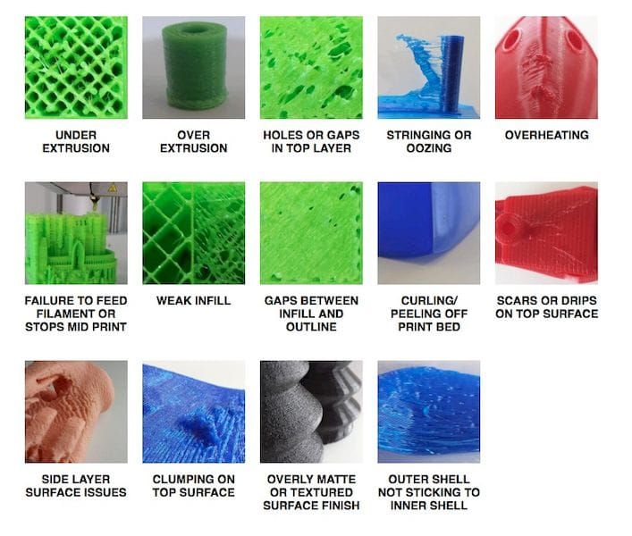
Since each body block followed the same pattern, it makes sense to simply print one removable block that will allow the customer to understand the typology of the typical device to print as a single block or separate along the seam.
This method usually works for models that do not have straight lines, such as typical building blocks, but complex structures, such as detailed building sections, bridges, pavilions, or airports.
First, break these models down into components that can be 3D printed with minimal supports. This saves post-processing time (removing supports for delicate models can be tedious) and reduces material costs and print times.
This bridge example demonstrates multiple partitioning methods. First, the model is divided into several parts (Figure a). While they fit the
Form 2 build platform, they require painstaking removal of supports around more delicate areas such as cables and railings.
To solve this problem, each part is broken down into three sub-components: base plate and railing, vertical tensile cables and solar panels on top (figure b). They can be printed with significantly fewer supports, making it easier to finish,
Once completed, the components simply need to be assembled using the alignment functions that were included in the design phase. Smaller parts are also easier to place on a single build platform, with the entire bridge being printed from five 100ml parts.
Model from T.Y. Lin Architects
This site model was created using laser-cut fiberboard. The primary building was 3D printed from clear and white resin. Model by Schwarz Silver Architects
Materials
Materials play an important role in conveying the basic design concept. It is not always necessary to model the exact color and texture of a material, but it can help separate different materials. Dividing a model into its components allows for the display of materiality, as parts can be printed in different materials or individually dyed in different colors.
The transparent façade is illuminated from within, simulating the visual conditions of this site at night.
Formlabs Matte Resins
Black, White and Gray out of the printer have a smooth, opaque finish and provide an excellent neutral palette for architectural models. Gray and white resins are also easy to process and can be finished with just a few coats of paint, as discussed further in the finishing section of this document.
Formlabs Clear Resin is excellent for printing features that mimic translucent materials. If your model requires more transparency, you can simply dip the printed part in clear resin and let it dry evenly, as described in this article on making clear resin parts. You can also spray any clear coats on the model to increase the transparency and glossiness of the surface.
3D PRINTING AND TRADITIONAL MATERIALS
This model uses the Form 2 to print very fine details such as the cornice, clock and railing. Modeled by Miles Burke Architectural Models Inc.
Instead of 3D printing an entire building, sometimes it's better to print only complex components. Complex facades, slings and cornice details are excellent candidates for SLA 3D printing. Flat walls, floor slabs and topography can be laser cut or even hand-drawn
This complex façade is parametrically designed from solar trajectory analysis and would be incredibly difficult to fabricate in any other way at this scale.
Software Workflow
Good printing comes from a well-designed 3D model. This section will cover modeling best practices and workflows for printing in some of the most common CAD environments:
Revit, SketchUp and Rhino
CAD software is typically the bottleneck in the transition from drawing to 3D printed model
General workflows
IMZ workflow
902 PreForm
Although BIM (Building Information Model) software is popular with architecture firms, it is not always used for direct 3D printing models. There are some high level steps that you can take
take to create a 3D printed model from these programs. This workflow is widely applied to Autodesk Revit or Graphisoft ArchiCAD software, both of which are IMZ parametric modeling programs.
PREPARE THE FILE
STEP 1: Prepare a separate stand-alone file
STEP 2: Manage components: remove ducts, double glazing, HVAC units and internal parts that will not be visible in the model
STEP 3: Select all components to be sealed (eg doors, windows, walls, slabs). The parametric nature of the model allows you to simultaneously compact the dimensions of several objects.
EXPORT FILE
Select the scale at which you want to export the file. Select the export options depending on the needs of your model:
EXPORT AS STL
Exporting the file as a mesh is very difficult to manipulate, so this is only useful if you don't want to edit any geometry after this step.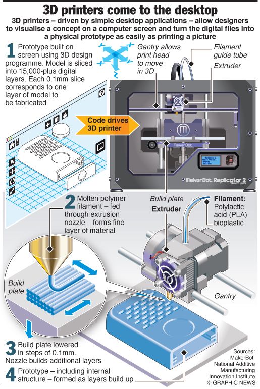 You can then use your software to correct the mesh of your choice, as well as subdivide the mesh along the main Cartesian planes.
EXPORT AS 3D DWG
Export as surfaces allows you to easily manage and edit geometry in Rhino or SketchUp. This step is recommended for those who want to split the model programmatically or by component, or split by a seam that is not on the normal Cartesian plane. You can then export the STL file from Rhino or SketchUp using the plug-in
EXPORT USING ARCHICAD
Perform a geometry transformation to Morphs and a "consistency check" before exporting the model as STL. When printing in parts, use tool
"Divide" to cut the model for multiple platforms, if needed. This operation basically creates printable files, but a quick check in mesh repair/analysis software never hurts.
USING STL REVIT EXPORTER
This method automatically removes smaller details such as doorknobs and railings. However, it is not reliable and still often requires some post-processing in other CAD environments before being sent to print.
Surface modeling workflow
AutoCAD → Rhino/SketchUp → Model Diagnostics → PreForm
This workflow is often an easier approach and starts with 2D drawings solely for the purpose of 3D printing
FILE PREPARATION 2 STEP 1: Hide unwanted layers STEP 2: Identify and remove unwanted elements such as furniture, trees, etc. EXPORT FILE STEP 1: Export the simplified drawing from Rhino as DWG STEP 2: Import into Rhino STEP 4: Start extruding and trimming until you get the outer shell. STEP 5: Export as STL STEP 6: Mesh Analysis/Correction STEP 7: Import to PreForm Note: If the model will be printed in several parts, split it before exporting as STL THICKNESS WITH RHINO Instead of parametrically controlling the thickness of components directly in the BIM file, you can also use the BoxEdit component in Rhino. This allows you to simultaneously scale a number of elements with respect to their center lines. BoxEdit is ideal for models that need to be scaled parallel to three Cartesian axes. Non-uniform scaling is a little trickier. For non-rectilinear geometries, we suggest converting the part to a mesh and then using the Weaverbird thicken command, which simply offsets any non-standard mesh geometry outward by a given distance. Alternatively, it is possible to "split" complex parts into surfaces and then offset them instead of importing volumes from Revit. SELECTING SMALL GEOMETRIES WITH RHINO Another valuable Rhino feature is the SelSmall command, which allows you to select all elements in the Stage that are smaller than a custom bounding box. You can then select those objects and use BoxEdit for individual scaling or just remove them. This is useful when you are dealing with a file that does not have a well organized layer system. Although performing a logical connection on all geometries is ideal, often the problem can be solved with simple overlapping geometries. PreForm will interpret them as one closed geometry in most cases, but be sure to check printability with the "slicer" tool in the right pane in PreForm . CONTINUOUS / LOGICAL JOINT GEOMETRY Note : PreForm is Formlabs free software that prepares your 3D model for printing in Form 2. Once the part is set up, you can save it as a FORM file for future use in preform. COMPUTATION WORKFLOW Although it is a less common workflow, computational design is slowly being introduced into mainstream architectural workflows. Software such as Grasshopper and Dynamo are used to create parametrically generated geometries that are often so complex that they can only be created with 3D printing. Since geometries are already easy to manipulate, it's usually best to create a separate component that allows you to easily control the basic dimensions of all thin objects. MeshMixer) and resizing until you arrive at a printable file. All workflows described below share a potential "generic diagnosis". This is an optional (but often necessary) step to ensure that the model is fully printable. Free programs such as Autodesk's MeshMixer and Netfabb are tools that allow you to repair, smooth, cavity, and split 3D print files. MESH FIX Formlabs PreForm software uses Netfabb's built-in mesh fix, so NetFabb and MeshMixer must be used for custom fixes or to preview problem spots in print. Materialize Magics is a great proprietary tool that covers the entire preprint workflow for a wide range of printer types. The mesh patching software part is most important to the Form 2 print workflow and can save you a decent amount of preparation time. Netfabb has a beautiful built-in model cutter that allows you to effectively split and restore large files along any Cartesian plane. SPLITTING THE MODEL It is also possible to split the model in NetFabb, which splits and fixes the split parts into printable volumes. In Rhino, you will need to close open volumes. Be sure to leave a tolerance of ~0.25mm between adjacent parts, this will allow them to be inserted without friction. See our technical data sheet for details on tolerances. PREFORM SLICER Architectural models are highly detailed and it is often difficult to isolate each print issue. A combination of the above practices and mesh repair software is usually used for almost all problems, but it's always wise to use the PreForm Slicer tool to make sure there are no thin unsupported areas and enclosed volumes (such as rooms with no doors, elevator shafts, and parking spaces) . “Building and architecture structures are not meant to be 3D printed, they are meant to be built. This creates problems of scale and complex geometry. Matt Lemay. Lead Enterprise Solutions Provider, Autodesk Customer Service The modeling strategy section of this booklet covers some ways of splitting and aligning parts together, but glue is always needed for a secure connection. Architectural parts are bonded in two main ways: CYANOACRYLATE Cyanoacrylate (CA or Super Glue) creates a fast, strong enough bond, ideal for small to medium sized parts. CA does not bond dirty surfaces well, so be sure to thoroughly clean the part before applying adhesive to the surface of the model. POLYMER For smaller prints, you can use liquid resin as a binder. Dispense a small amount of resin into the tray from a bottle or cartridge, use a dropper or syringe to lift it up, and place it on the surface of the part to be bonded. Join parts and wipe off any excess resin that may be spilling around the edges. To cure the resin and bond the parts, use a 5 mW laser pen at 405 nm and point it at the bonding area around the parts. This method creates a chemical bond, just as if the part had been printed on your SLA 3D printer, but only applies to small bonding surfaces because a low power laser pen cannot penetrate the model deep enough to create a strong bond . FINISHING Parts printed on Form 2, especially matte standard resins, have a smooth surface immediately after exiting the printer. However, visible areas with supports almost always require sanding. In addition, you can prime and paint parts in any desired color. GRINDING Sanding will help you remove the support marks and any remaining inaccuracies from your model. Start by carefully dry sanding the surface of the part using ~150 grit sandpaper to remove large support marks and smooth out the edges of the joint. In most cases these two steps will create a fairly even finish, but you can continue to increase the grit size of the sanding paper by a factor of 2 and use wet sanding on the entire piece until the surface is the desired smoothness. Once you have finished sanding your model, wash the model in soapy water to remove any dust or debris and dry thoroughly before proceeding to the last step. The architectural models are very detailed and it is quite difficult to access certain areas with only sandpaper. You can use different sizes of nail files to get to problem areas of the model. PRIMER AND PAINTING Priming is required before parts are painted to ensure the paint adheres to the surface. Priming can also make it easier to find areas that require additional finishing. A quick spray of primer over the model makes the support marks very visible, so you can instantly identify areas that need additional sanding.
 In this case, it's a simple matter of trial and error; running the exported geometries with a print test (PreForm,
 Model Diagnosis

 By combining Netfabb's powerful mesh repair tools with the precision of the Form 2, you can prototype and visualize designs faster and in more detail, benefiting more for your business and speeding up your project's design review process.”
 Post-Processing
Joining
 Once the surface of the part is smooth, wet sand with 320mm sandpaper to remove any remaining layer lines. Move the sandpaper randomly to avoid grain formation.
Learn more